Table of Contents
Advertisement
Quick Links
Characteristics
General
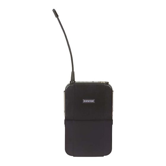
Controls and Connectors
4
3
2
1
1. Antenna
2. Power/Battery Fuel Gauge LEDs
3. Power ON/OFF Switch
4. Input Connector
5. Rf/Audio Mute Switch Input Connector
6. Input Attenuation Control
1998, Shure Brothers Inc.
25A1043 (RI)
Service Manual
UC1
UC1L Body-Pack
/
UHF Transmitter
The Shure UC1/UC1L Body-Pack Transmitter is microprocessor-
controlled, operating in the 774 – 862 MHz frequency range. The UC1/
UC1L is used in mid-level installed sound, rental, and concert sound
applications. Six frequency range variations are available.
10
11
Figure 1. UC1 Controls and Connectors
Service Note: Shure recommends that all service procedures be
performed by a Factory-Authorized Service Center or that the
product be returned directly to Shure Brothers Inc.
8
9
7
12
7. Audio Gain Control
8. Group Rotary Switch
9. Channel Rotary Switch
10. Battery Compartment
11. Battery Cover Release Tabs
12. Battery Compartment Cover
5
6
Printed in U.S.A.
Advertisement
Table of Contents

Related Manuals for Shure UC1L


Summary of Contents for Shure UC1L
-
Page 1: Service Manual
The Shure UC1/UC1L Body-Pack Transmitter is microprocessor- controlled, operating in the 774 – 862 MHz frequency range. The UC1/ UC1L is used in mid-level installed sound, rental, and concert sound applications. Six frequency range variations are available. Controls and Connectors 1. -
Page 2: Circuit Description
Shure UC1 Body-Pack UHF Transmitter Circuit Description LIMITER CONTROL INPUT Σ MIC. / AUDIO MIC. / INSTR. INSTR. TONE KEY LIMITER CONTROL OUTPUT REMOTE REG. BATTERY CALL ID MUTE TONE KEY MGMT. CIRCUIT & FUEL GAUGE FROM ON / OFF UNREG. - Page 3 Shure UC1 Body-Pack UHF Transmitter an external amplifier, U202B. U203 performs a 2:1 logarithmic compres- sion of the audio signal. Transistors Q201 and Q202, with crystal Y201, form the tone key oscillator circuit that provides a stable, continuous 32.768 kHz sine wave.
- Page 4 Shure UC1 Body-Pack UHF Transmitter The audio is then fed to the tuning voltage pin of the voltage- controlled oscillator ( ) and modulates the carrier directly. Using a phase-locked loop ( ) frequency synthesized system eliminates the need for multiplier stages and results in a much higher degree of spectral purity.
- Page 5 Shure UC1 Body-Pack UHF Transmitter The transmitter is unmuted by bringing the gate low ( RFUNMUTE During transmitter power conditions, the rf power is first muted by bringing the base of Q103 and Q105 high. When the rf is muted this...
- Page 6 Shure UC1 Body-Pack UHF Transmitter Battery Management Section The microcontroller provides for low battery shutdown. The shut- down threshold is 1.88 Vdc 10%. A voltage lower than the shutdown threshold on pin 17 of the U101 microcontroller shuts down the transmit- ter.
- Page 7 Shure UC1 Body-Pack UHF Transmitter Power Switch and Remote Mute Switch Interface When a transmitter is turned off, the signal goes to logic low PWRDN1 on U101, pin 19. The same signal is also forced low when a remote mute switch closes the tip contact to the sleeve ground.
- Page 8 Shure UC1 Body-Pack UHF Transmitter Notes This page intentionally left blank. 25A1043 (RI) Notes...
-
Page 9: Functional Test
Shure UC1 Body-Pack UHF Transmitter Functional Test Verify operation and reported malfunction, referring to the product User Guide for a description of the unit as well as information on its operation, troubleshooting, and technical data. Disassembly and Assembly ! CAUTION ! Observe precautions when handling this static-sensitive device. - Page 10 Shure UC1 Body-Pack UHF Transmitter Reassembly After completing all repairs and alignment, reassemble the UC1: 1. Place the printed circuit boards back into the case, making sure the multi-pin connectors on the board mate and the TINI QG/ connector is seated correctly.
-
Page 11: Service Procedures
0 dBV = 2.2 dBu 0 dBu = 0 dBm, assuming the load = 600 Ω Test Equipment Most test equipment needed is described in the Shure Wireless Service Equipment Manual . The following test equipment (or approved equivalent) is also needed. - Page 12 Shure UC1 Body-Pack UHF Transmitter Test Set-Up TP131 BIAS J204 D206 SIDE 1 C130 U203 C208 TP130 *R144 C203 R149 S102 U108 C510 Q219 TP+5 TPA1 U501 STR1 TP18 GREEN Q104 C246 Q221 Q223 TP21 TP111 U201 TP103 TP104 TP108...
-
Page 13: Alignment Set-Up
Shure UC1 Body-Pack UHF Transmitter Alignment Alignment Set-Up Table 2 lists the group carrier frequencies and tuning voltages for all the service tests that follow. Table 2 Group Carrier Frequencies and Tuning Voltages (in order by carrier frequency) Group Channel... - Page 14 Shure UC1 Body-Pack UHF Transmitter Frequency Use this service procedure to correctly align the transmitter’s operating (output) frequency. C510 tunes the voltage-controlled oscillator (VCO) to the operating frequency selected, with a 1 – 4 Vdc tuning range. C123 adjusts the reference oscillator on the synthesizer.
-
Page 15: Power Output Measurement
Shure UC1 Body-Pack UHF Transmitter Power Output Measurement The output power measurement ensures that the output signal is strong enough for sufficient range when the system is in use. The output power measurement also verifies that the output power is not above the specified maximum level, to ensure compliance with regulatory agencies’... - Page 16 Shure UC1 Body-Pack UHF Transmitter Deviation Reference Voltage: Using a UC4 or U4S Receiver Deviation must be set to make sure the companding systems be- tween the transmitter and receiver correctly track each other. The level coming out of the transmitter’s audio compressor must match the level going into the receiver’s audio expander.
- Page 17 Shure UC1 Body-Pack UHF Transmitter Deviation Adjustment Voltage: Using a UC4 or U4S Receiver AUDIO ANALYZER J301 R149 UC1, SIDE 2 UC1, SIDE 1 UC1 Transmitter Audio Analyzer Power: +9 Vdc Measurement: AC level Gain: Minimum Output: 1 kHz Filters:...
- Page 18 Shure UC1 Body-Pack UHF Transmitter Deviation Adjustment Voltage: Using a UC4 or U4S Receiver AUDIO ANALYZER S501 (TONE KEY SWITCH) R149 W101 UC1, SIDE 1 UC4 Receiver UC1 Transmitter Audio Analyzer Output: Unbalanced Power: + 9 Vdc Measurement: AC level...
- Page 19 Shure UC1 Body-Pack UHF Transmitter Deviation Reference Voltage: Using a Modified SC4 IF Receiver Deviation tests can also be performed using a modified SC4 IF receiver. For instructions on modifying an SC4 receiver, consult the Shure Service Equipment manual. ZAD–1 MIXER...
- Page 20 Shure UC1 Body-Pack UHF Transmitter Deviation Adjustment Voltage: Using an SC4 IF Receiver AUDIO ANALYZER J301 R149 UC1, SIDE 2 UC1, SIDE 1 UC1 Transmitter Audio Analyzer Power: +9 Vdc Measurement: AC level Gain: Minimum Output: 1 kHz Filters: Low-Pass (30 kHz): ON High-Pass (400 Hz): ON Figure 11.
- Page 21 Shure UC1 Body-Pack UHF Transmitter Deviation Adjustment Voltage: Using a Modified SC4 IF Receiver ZAD–1 MIXER TRANSMITTER AUDIO ANTENNA MODIFIED SC4 IF RECEIVER OUTPUT ANTENNA INPUT B AUDIO OUT TONE KEY SWITCH: ON DC BLOCK AUDIO ANALYZER RF SIGNAL GENERATOR...
-
Page 22: Operating Specifications
Shure UC1 Body-Pack UHF Transmitter Operating Specifications After tuning, the unit should meet the following specifications. Table 3 Operating Specifications Specification Minimum Typical Maximum Current drain 50 mA 60 mA 70 mA Frequency –1.0 kHz See Table 2 +1.0 kHz Audio freq response @ 100 Hz wrt 1 k –5.0 dB... - Page 23 Shure UC1 Body-Pack UHF Transmitter Bench Checks Dc Problems Make all dc measurements with respect to the rf ground, unless otherwise specified. Verify that the battery voltage is between 6.0 Vdc and 9.5 Vdc. Check for +5 Vdc at labeled test points on the audio and rf boards.
- Page 24 Shure UC1 Body-Pack UHF Transmitter Low Rf Output Power Check the polarity of the low-pass filters U107, U108, and U109. (Pin 1 is marked with a dash.) Check for missing ground connections. Verify the VCO output power at R128 and U104, pin 8.
-
Page 25: Audio Problems
Shure UC1 Body-Pack UHF Transmitter Audio Problems No Tone Key No tone key means that the 32 kHz tone key sidebands are not visible when the carrier is viewed on a spectrum analyzer. If tone key levels are there but are too low, the deviation is off and needs to be recalibrated. - Page 26 Shure UC1 Body-Pack UHF Transmitter Notes This page intentionally left blank. 25A1043 (RI) Notes...
-
Page 27: Product Changes
Shure UC1 Body-Pack UHF Transmitter Replacement Parts and Drawings Product Changes Six versions of the UC1 and UC1L transmitters are available for use in various countries. Each version is identified below by country code, country designation, frequency range, and printed circuit board number. - Page 28 Shure UC1 Body-Pack UHF Transmitter Table 6 Printed Circuit Board Components Reference Shure Part Designation Description Number C123 Capacitor, trimmer, 5 – 40 pF 152F03 C510 Capacitor, trimmer, 1.4 – 3.0 pF 152A04 D101–104 Diode, dual switching, SOT-23 184A07 D105, 206...
- Page 29 Shure UC1 Body-Pack UHF Transmitter Table 7 Group Designators (in order by frequency) Frequency Country Country κΩ Range Designation Code kΩ kΩ kΩ kΩ (MHz) 774–782 Netherlands – – – – 782–806 US & Canada – – – – –...
- Page 30 Shure UC1 Body-Pack UHF Transmitter Table 8 Frequency Dependent Components (in order by frequency) Frequency Country Country C117 C118 C173 C215 Range (MHz) Designation Code 774–782 Netherlands 0.047 – – 782–806 US & Canada – – – – 797–806 Japan 0.047...
- Page 31 Shure UC1 Body-Pack UHF Transmitter 25A1043 (RI) Replacement Parts and Drawings...
- Page 32 Shure UC1 Body-Pack UHF Transmitter 25A1043 (RI) Replacement Parts and Drawings...
Need help?
Do you have a question about the UC1L and is the answer not in the manual?
Questions and answers