Table of Contents
Advertisement
Quick Links
OWNER'S MANUAL & INSTALLATION MANUAL
MANUEL DE L'UTILISATEUR & MANUEL D'INSTALLATION
MANUAL DEL PROPIETARIO & MANUAL DE INSTALACIÓN
MANUALE DEL PROPRIETARIO & MANUALE DI INSTALLAZIONE
êäéÇéÑëíÇé èéãúáéÇÄíÖãü à àçëíêìäñàü èé ìëíÄçéÇäÖ
AIR CONDITIONER
CLIMATISEUR
ACONDICIONADOR DE AIRE
CONDIZIONATORE D'ARIA
äéçÑàñàéçÖê
Please read this owner's manual carefully before using air conditioner and reserve
this manual in case of further reference.
Nous vous prions de lire attentivement le présent manuel avant d'utiliser cette unité
d'air climatisé et de le conserver pour pouvoir le consulter en cas de besoin.
Lea el manual del propietario detenidamente antes de utilizar el acondicionador de
aire, y guárdelo como referencia para el futuro.
Vi pregiamo di leggere con attenzione questo manuale del proprietario prima di
utilizzare quest'unità d'aria condizionata e tenerlo per posteriori riferimenti.
èÂʉ ˜ÂÏ ÔÓθÁÓ‚‡Ú¸Òfl ÍÓ̉ˈËÓÌÂÓÏ, ÒÓı‡ÌflÈÚ ˝ÚÛ ËÌÒÚÛÍˆË˛ ‰Îfl
ÒÔ‡‚ÓÍ, ÍÓÚÓ˚ ÏÓ„ÛÚ ÔÓ̇‰Ó·ËÚ¸Òfl ‚ ·Û‰Û˘ÂÏ.
4527454/02-Cover
1
06/22/2004, 5:08 PM
Advertisement
Chapters
Table of Contents

Related Manuals for Electra KN-27SH


Summary of Contents for Electra KN-27SH
-
Page 1: Air Conditioner
OWNER’S MANUAL & INSTALLATION MANUAL MANUEL DE L’UTILISATEUR & MANUEL D’INSTALLATION MANUAL DEL PROPIETARIO & MANUAL DE INSTALACIÓN MANUALE DEL PROPRIETARIO & MANUALE DI INSTALLAZIONE êäéÇéÑëíÇé èéãúáéÇÄíÖãü à àçëíêìäñàü èé ìëíÄçéÇäÖ AIR CONDITIONER CLIMATISEUR ACONDICIONADOR DE AIRE CONDIZIONATORE D’ARIA äéçÑàñàéçÖê Please read this owner’s manual carefully before using air conditioner and reserve this manual in case of further reference. -
Page 2: Table Of Contents
CONTENTS INSTALLATION ........................1 REQUIREMENT FOR ELECTRIC SAFETY ............... 2 PARTS NAMES AND THEIR FUNCTIONS ................ 3 OPERATION ATTENTION ....................4 TEMPORARY OPERATIONS ..................... 5 ADJUSTING AIR FLOW DIRECTION ................. 5 HINTS FOR ECONOMICAL OPERATION ................6 MAINTAINANCE ......................... 6 PHENOMENA NOT CONCERNING MALFUNCTIONS ............ -
Page 3: Installation
INSTALLATION CAUTION Don’t attempt to install this unit yourself. The unit requires installation by qualified persons. POWER • Be sure to use the special switch with effective grounding. The connector socket in the air conditioner has been grounding already, please don’t change it freely. •... -
Page 4: Requirement For Electric Safety
REQUIREMENT FOR ELECTRIC SAFETY 1. The wiring work must be done by qualified person. 2. All the wiring must be performed according to safety rules. 3. The main switch must be linked well with the earth. 4. A separate power source for the air conditioner according to the specifications as follow must be provided. -
Page 5: Parts Names And Their Functions
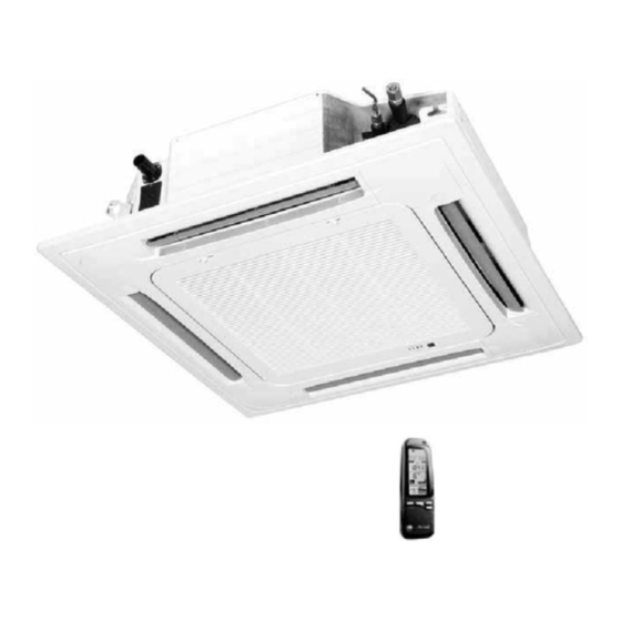
The air conditioner consists of the indoor unit , the outdoor unit , the connecting pipe and the remote controller. Display Panel NOTICE This chart is based on KN-27SH, so, a few differences may exist on the outlook and functions from yours. NAMES AND FUNCTIONS a) Indoor unit... -
Page 6: Operation Attention
OPERATION ATTENTION NOTICE • Please read this “Owner’s Manual” carefully operation. • This air conditioner is designed to provide comfortable circumstances and to guarantee the functions described in this manual only. 1. CHECK BEFORE OPERATION • Check that the ground wiring is not broken off and is connected well. •... -
Page 7: Temporary Operations
TEMPORARY OPERATIONS This function is used to operate the unit temporarily in case you misplace the remote controller or its batteries are exhausted. Two modes including mandatory HEAT and mandatory COOL can be selected through the TEMPORARY BUTTON on the air inlet grill control box of the indoor unit. -
Page 8: Hints For Economical Operation
HINTS FOR ECONOMICAL OPERATION The following should be noticed ensure an economical operation. (Refer to corresponding chapter for details) • Adjust the air flow direction properly to avoid winding toward your body. • Adjust the room temperature properly to get a comfortable situation and to avoid supercooling and superheat. - Page 9 2. Take out the air-in grill (together with the air filter shown in sketch B) Pull the air-in grill down at 45° and lift it up to take out the grill. 3. Dismantle the air filter. 4. Clean the air filter (Vacuum cleaner or pure water may be used to clean the air filter. If the dust accumulation is too heavy, please use soft brush and mild detergent to clean it and dry out in cool place).
-
Page 10: Phenomena Not Concerning Malfunctions
RESTART AFTER A LONG TIME 1. Check before operation • Check that air outlets of the outdoor and indoor are not blocked. • Check that the ground wiring is not broken off and is connected well. 2. Restore the air filter and the front panel The air filter and the front panel must be fixed to the original position after having been cleaned. -
Page 11: Troubles And Causes (Concerning The Unit)
TROUBLES AND CAUSES (concerning the unit) 1. If any or the following conditions occurs, stop the air conditioner immediately, set off the power: • The indicator lamps flash rapidly (two times per second), you disconnect the unit with the power and then connect it again, but the lamp still flashes. -
Page 12: Reparation
The Transmission indicator Never Comes On Symptoms Causes Reason and Disposal The remote control signal • Check whether the batteries The remote control signal is not is not transmitted when in the remote controller are transmitted, because the power the I/O button is pushed. exhausted. -
Page 13: Installation Manual
INSTALLATION MANUAL MANUEL D’INSTALLATION MANUAL DE INSTALACIÓN MANUALE DI INSTALLAZIONE àçëíêìäñàü èé ìëíÄçéÇäÖ For correct installation, read this manual before starting installation . This manual may be subject to change without notice for purpose of improvement Afin d’effectuer une installation correcte, lire le manuel avant de commencer l’installation. - Page 14 CONTENTS 1. PRECAUTIONS ......................1 2. INSTALLATION INFORMATION ................... 2 3. ATTACHED FITTINGS ....................3 4. INSTALLATION PLACE ....................4 5. INDOOR UNIT INSTALLATION ..................5 6. OUTDOOR UNIT INSTALLATION ................8 7. INSTALL THE CONNECTING PIPE ................9 8. CONNECT THE DAIN PIPE ..................13 9.
-
Page 15: Precautions
PRECAUTION SAFETY CONSIDERATIONS Installation and servicing of air conditioning equipment can be hazardous due to system pressure and electric components. Only trained and qualified service personnel should install, repair or service air conditioning equipment. All other operations should be performed by trained service personnel. When working on air conditioning equipment, observe precautions in the literature, tags and labels attached to the unit and other safety precautions that may apply. -
Page 16: Installation Information
NOTE Remark per EMC Directive 89/336/EEC To prevent flicker impressions during the start of the compressor (technical process), following installation conditions do apply. 1. The power connection for the air conditioner has to be done at the main power distribution. The distribution has to be of a low impedance, normally the required impedance reaches at a 32 A fusing point. -
Page 17: Attached Fittings
ATTACHED FITTINGS Please check whether the following fittings are of full scope. If there are some attached fittings free from use, please restore them carefully. Installation fittings Drainpipe Fittings 1. Expansible hook ........4 5. Out-let pipe sheath ........1 2. -
Page 18: Installation Place
INSTALLATION PLACE CAUTION Location in the following places may cause malfunction of the machine. (If unavoidable, please consult your local dealer) a. There is petrolatum existing. b. There is salty air surrounding (near the coast) c. There is caustic gas (the sulfide, for example) existing in the air (near a hot spring). d. -
Page 19: Indoor Unit Installation
INDOOR UNIT INSTALLATION 1. Install the main body A. The existing ceiling (to be horizontal) a. Please cut a quadrangular hole of 880X880mm in the ceiling according to the shape of the installation paper board. (Refer to Chart 3, 4) •... - Page 20 Note: 24/27/30 Series B 240mm 36/45 Series B 310mm Hook Body Body Central hole Ceiling Panel Chart 4 Installation paper Body M6X12 board Body Chart 7 Ceiling Chart 6 Chart 5 B. New built houses and ceilings a. In the case of new built house, the hook can be embedded in advance (refer to the A. B mentioned above).
- Page 21 (3)Install the panel a. Align the swing motor on the panel to the tubing joints of the body properly. (Refer to chart 11) b. Fix hooks of the panel at swing motor and its opposite sides to the hooks of corresponding water receiver.
-
Page 22: Outdoor Unit Installation
OUTDOOR UNIT INSTALLATION CAUTIONS • Keep this unit away from direct radiation of the sun or other heaters. If unavoidable, please cover it with a shelter. • In places hear coast or with a high attitude where the wind is violent, please install the outdoor unit against the wall to ensure normal performance. -
Page 23: Install The Connecting Pipe
INSTALL THE CONNECTING PIPE CAUTIONS check whether the height drop between the indoor unit and outdoor unit , the length of refrigerant pipe, and the number of the bends meet the following requirements: The max height drop ........................20m. (If the height drop is more than 10m, you had better put the outdoor unit over above the indoor unit.) The length of refrigerant pipe .................. - Page 24 Use the market brass pipe • Be sure to use the same insulating materials when you buy the brass pipe. 2. Locate The Pipes • Drill a hole in the wall (suitable just for the size of the wall conduit, 50,53,71 series diameter is M90mm, and 120 series diameter is M105mm in general), then set on the fittings such as the wall conduit and its cover.
- Page 25 Expel the air with a vacuum pump (Refer to Chart 27) (please refer to its manual for the way of using manifold value) 1. Loosen and remove the maintenance nuts of stop values A and B, and connect the charge hose of the manifold value with the maintenance terminator of stop value A.
-
Page 26: Check The Leakage
7. Disassemble the charge hose from the repair-mouth of stop value A, and fasten the unit. Manifold value Multi-meter Pressure meter Outdoor Indoor unit Gas-side unit -76CmHg Hi-lever Lo-lever Charge hose Charge hose Liquid side Vacuum Trap Pipe joint pump Chart 26 Chart 25 Lo-lever... -
Page 27: Connect The Drain Pipe
INSULATION • Be sure to with insulating materials cover all the exposed parts of the flare pipe joints and refrigerant pipe on the liquid-side and the gas-side .Ensure that there is no gap between them. • Incomplete insulation may cause water condensation. CONNECT THE DRAIN PIPE 1. - Page 28 2. Drainage test • Check whether the drainpipe is unhindered • New built house should have this test done before paving the ceiling. 1) Refer to chart 32) Pump joint Test cover Test mouth Body Slow tube Water-receiver Drain plug Chart 32 2) Turn on the power, and operate the air conditioner under the “COOLING “...
-
Page 29: Wiring
WIRING CAUTION 1. The air conditioner should use separate power supply with rated voltage. 2. The external power supply to the air conditioner should have ground wiring, which is linked to the ground wiring of the indoor and outdoor unit. 3. - Page 30 3. ELECTRICAL CONNECTIONS 3.1 Power supply WARNING Electrical connection shall be made only by authorized electricians and in accordance with local electrical requirements and codes. The system must be grounded. Single-phase models and three phase models are available; for each of them, the necessary wiring diagram is shown.
- Page 31 OUTDOOR HEATER 1. Outdoor unit 8. Wireless Remote Control 2. Inter connecting cable 9. Wired Remote Control (optional) 3. Power supply 10. Remote ON/OFF Switch (by installer) 4. Semi-automatic switch 11. Control Cable (Shielded) 5. Indoor unit 12. Switch ON/OFF (by installer) 6.
- Page 32 INDOOR 3-CORE Cable 3X1.5mm 3-CORE Cable YZW-300/500 3X1.5mm 5-CORE Cable RW-300/500 5X1.5mm POWER: 380V~50Hz Note: The cooling only type without the link listed by broken line KN-27 AIR CONDITIONER LINK CIRCUIT Chart 37 SZ000288/En 06/22/2004, 5:07 PM...
- Page 33 INDOOR 3-CORE Cable 3X2.5mm POWER: 220-240V~50Hz 5-CORE Cable 5X2.5mm Note: The cooling only type without the link listed by broken line KN-24/27 AIR CONDITIONER LINK CIRCUIT Chart 38 SZ000288/En 06/22/2004, 5:07 PM...
-
Page 34: Test Operation
TSET OPERATION 1. The test operation must be carried out after the entire installation has been completed. 2. Please confirm the following points before the test operation. • The indoor unit and outdoor unit are installed properly. • Tubing and wiring are correctly completed. •... - Page 35 Part No: 4527454/02 4527454/02-Cover 06/22/2004, 5:08 PM...
Need help?
Do you have a question about the KN-27SH and is the answer not in the manual?
Questions and answers