Marantz PMD570 Service Manual
Pmd570 series solid state recorder
Hide thumbs
Also See for PMD570:
- User manual (55 pages) ,
- Owner's manual addendum (7 pages) ,
- User manual (55 pages)
Table of Contents
Advertisement
Service
Manual
POWER ON/OFF
SECTION
1. TECHNICAL SPECIFICATIONS ............................................................................................ 1
2. SERVICE MODE .................................................................................................................... 2
3. LCD CONTRAST ADJUSTMENT .......................................................................................... 3
4. MAIN MICROPROCESSOR (QU01) UPDATE PROCEDURE .............................................. 3
5. WIRING DIAGRAM .............................................................................................................. 19
6. BLOCK DIAGRAM ............................................................................................................... 21
7. SCHEMATIC DIAGRAM ....................................................................................................... 23
8. PARTS LOCATION .............................................................................................................. 49
9. MICROPROCESSOR AND IC DATA ................................................................................... 55
10. EXPLODED VIEW AND PARTS LIST .................................................................................. 69
11. ELECTRICAL PARTS LIST .................................................................................................. 73
Please use this service manual with referring to the user guide (D.F.U) without fail.
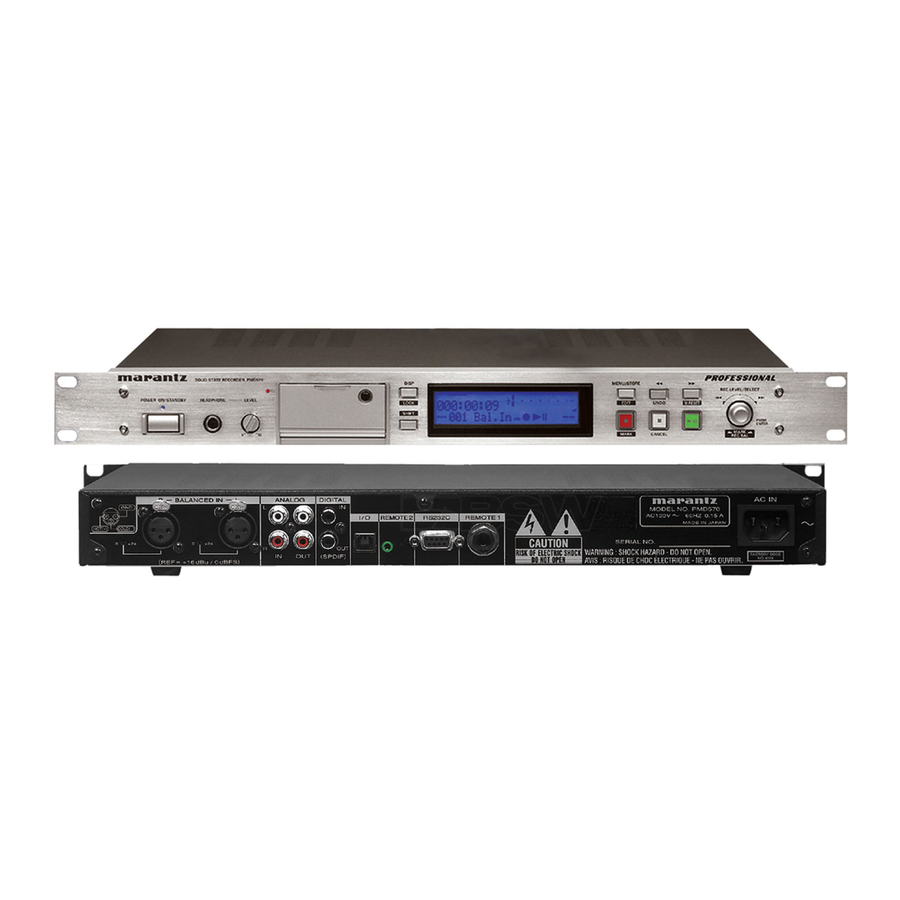
SOLID STATE RECORDER PMD570
DISPLAY
HEADPHONE
LEVEL
LOCK
SHIFT
0
10
TABLE OF CONTENTS
PMD570
PMD570 /
Solid State Recorder
MENU/STORE
TOTAL TRACKTIME
A-B
REC REMAIN kbps
L
-dB
00
40
20
1
6
2
0
over
EDIT
UNDO
kHz
2
R
AM
PM
S.SKIP
-dB
TRACK
MARK
LINE
MARK
CANCEL
F1B /N1B /U1B
/F1S /N1S /U1S
REC LEVEL/SELECT
M. RESET
PUSH
ENTER
MARK
REC BAL
PAGE
Part no. 49AS855010
First Issue 2004.04
ecm
Advertisement
Table of Contents

Related Manuals for Marantz PMD570


Summary of Contents for Marantz PMD570
-
Page 1: Table Of Contents
Service PMD570 / F1B /N1B /U1B /F1S /N1S /U1S Manual Solid State Recorder SOLID STATE RECORDER PMD570 MENU/STORE DISPLAY REC LEVEL/SELECT TOTAL TRACKTIME REC REMAIN kbps POWER ON/OFF HEADPHONE LEVEL over EDIT UNDO M. RESET LOCK SHIFT S.SKIP PUSH TRACK... - Page 2 MARANTZ Parts for your equipment are generally available to our National Marantz Subsidiary or Agent. ORDERING PARTS : Parts can be ordered either by mail or by Fax.. In both cases, the correct part number has to be specified.
-
Page 3: Technical Specifications
User Guide ..............1 * A CF card (Compact Flash™ memory card) or a Audio Microdrive™ is needed for the PMD570 to work. Also Frequency response ....... 20,000 Hz (-0.5dB) used in digital cameras, removable flash memory media Signal-to-Noise Ratio are widely available at consumer electronics retailers and IEC-A weighted ............ -
Page 4: Service Mode
2. SERVICE モード 2. SERVICE MODE 2.1. VERSION 確認 2.1. Micro Processor Version check 1. Keep inserting the CompactFlash, press the POWER but- 1. Compact Flashが挿入されている状態で、 MENU/STORE ton while pressing MENU/STORE and REC button. ボタンと REC ボタンを押しながら POWER ボタンを押し (MENU/STORE and REC button are pushed 3 seconds or ます。... -
Page 5: Lcd Contrast Adjustment
• RS232C cable straight type (9pin female - 9Pin male ) ・ マイコンアップデートディスク (*PMD570CDR) • Update Disc (*PMD570CDR) 4.1. 接続方法 1 PMD570とWindows PCのCOMポートをRS232Cケー 4.1. Connection ブルで接続します。 1. Connect COM port of Windows PC and PMD570 with RS232C cable. PMD570 Rear Panel RS232C Terminal RC232C cable Windows PC COM Port... - Page 6 4.2. Installs of The software 4.2. 書き込みソフトウェアのインストール (Flash Development Toolkit 3.0) (Flash Development Toolkit 3.0) 1. Open the CD-ROM (*PMD570CDR) Disc, and double click 1. CD-ROM (*PMD570CDR) の soft フォルダをダブルク soft folder. リックします。 2. Double click the FDT setup.exe 2. FDT setup.exe をダブルクリックします。...
- Page 7 3. Click Next. 3. インストールウィザードが起動します。 Next をクリックします。 4. 言語を選んで Next をクリックします。 4. Choose the language. And click Next. 5. Yes をクリックします。 5. Click Yes.
- Page 8 6. Check to the all check boxes. And click Next. 6. チェックボックス全てにチェックが入っていることを確 認して Next をクリックします。 7. Click Next. 7. Next をクリックします。 8. チェックボックス全てにチェックが入っていることを確 8. Check to the all check boxes. And click Next. 認して Next をクリックします。...
- Page 9 9. Click Next. 9. Next をクリックします。 10.Next をクリックします。 10. Click Next. 11.Next をクリックします。 11. Click Next.
- Page 10 12. Click Install. 12.Install をクリックします。 13. The status bar appears. 13.インストールを開始します。 14.Finishをクリックして書き込みソフトウェアのインストー 14. Click Finish. ルを完了します。...
- Page 11 4.3. The writing software setup procedure. 4.3. 書き込みソフトウェアの設定 Launch up the writing software. ソフトウェアの起動 1. Click Start / Programs / Renesas / Flash Development 1. Start / Programs / Renesas / Flash Development Toolkit Toolkit 3.0 / Flash Development Toolkit 3.0. 3.0 / Flash Development Toolkit 3.0 をクリックします。...
- Page 12 3. Check Create a new project workspace, and click OK. 3. Create a new project workspaceにチェックを入れ、 OK をクリックします。 4. PMD570 is inputted into the Workspace name. 4. Workspace Name に PMD570 と入力します。 (It is simultaneously inputted into Project Name.) (同時に Project Name にも入力されます。 ) Click OK.
- Page 13 6. Choose the Serial port No. in the Select Port. 6. Select Port から接続する Serial Port 番号を選び、クリッ Click Next. クします。Next をクリックします。 7. 24.58 is inputted into the "Enter the CPU crystal frequency 7. "Enter the CPU crystal frequency for the selected for the selected device:".
- Page 14 9. Check the Automatic in Protection. 9. Protection から Automatic にチェックを入れます。 Check the Advanced in Messaging. Messaging から Advanced にチェックを入れます。 Click Finish. Finish をクリックします。 以上で設定は完了です。...
- Page 15 出ますのでその都度 OK をクリックしてください) 3. Check Open a recent project workspace, and click OK. 3. Open a recent project workspaceをにチェックを入れて OK をクリックします。 4. The right click PMD570, and Click Add Files..4. 以下の画面が出ましたら、 2階層目にある PMD570 のア イコン上で右クリックをして、 Add Files をクリックし ます。...
- Page 16 5. Open the CD-ROM (*PMD570CDR Disc) and double click 5. アップデートディスク(*PMD570CDR)の soft フォル soft folder. ダをダブルクリックします。 6. Select PMD550.mot, and Click Add. 6. PMD550.mot を選択し、Add をクリックします。 7. The holder of PMD550.mot is made. 7. PMD550.mot のホルダーが出来ます。...
- Page 17 8. It checks that PMD570 and the COM port are connected 8. PMD570 と Windows PC の COM ポートの接続を確認し ます。 by RS232C cable. 9. Insert a thin rot to the hole and push the switch inside to 9. リアパネルのREMOTE 2 端子の横にある内部スイッチを...
- Page 18 14. Turn off the internal switch that has been turned on at step 9. OFF します。 NOTICE: 注意 この操作をしないと PMD570 の電源を入れた時、毎回書き When the internal switch is not turned off, the set becomes the mode of update of firmware every time to turn on the unit. 込みモードになります。 Push...
- Page 19 4.5. FACTORY MODE 4.5. FACTORY モード After the completion of update of Main microprocessor (QU01), ソフトのバージョンアップをした際には、 仕向け別に出荷設 to reset all setting to default status, follow the procedure below. 定(EEPROM の初期化)を行ないます。 /N version /N 仕向け 1. Press the POWER button while pressing MENU/STORE 1.
- Page 20 LCD 表示は消えます。 ) front panel disappear.) 5. “Connect” をクリックして、 接続状態にします 5. Click Connect. 6. 4階層目にある PMD550.mot のアイコン上で右クリック 6. The right click PMD570, and Click Download File. をして“Download File”をクリックします。 7. 以降は4.4. 書き込み方法の手順12から引き続いてを行な 7. After this procedure, continues to step 12. います。...
-
Page 21: Wiring Diagram
5. WIRING DIAGRAM P951 SUPPLY AC INLET PA01 REAR I / O J951 JM94 JA03 J971 P901 J851 J352 POWER J991 PM01 MAIN J993 J992 J852 JU06 J351 JU09 JU08 JU10 JC01 PC01 PF01 FRONT LED JF01 H/P VOL. JF03 PU81 ACCESS LED/ DETECTOR... -
Page 22: Block Diagram
6. BLOCK DIAGRAM LCD DRIVER KEY SW LCD DISPLAY NJU6469 1.6A QF01 AC/DC DC-DC POWER SUPPLY VF01 Converter +3.3V +3.3V +5V +3.3v DC 12.0v FOR up FOR DSP FOR LCD LED +1.6V EARTH FRONT uP FOR DSP +-9V STANDBY LED REC LED TMS320VC5416-160 FRONT uP... -
Page 23: Schematic Diagram
7. SCHEMATIC DIAGRAM L404 +3VD BLM11B601 DIG_IN C424 C414 10/10V 100n C416 CODEC_ADIN 470n CODEC_ADIN CODEC_WS R429 CODEC_WS R425 CODEC_BCLK +3VD 18k% CODEC_BCLK DIG_OUT CODEC_DACOUT CODEC_DACOUT DAI_IN R430 DAI_IN INTERFACE FOR DSP INT0 AVSS CODEC_WS CODEC_WS AVSS CODEC_MCLK CODEC_MCLK PM01-1/9 CODEC_BCLK CODEC_BCLK R428... - Page 24 +3VD DTA114EU RU17 PU81 4.7k +5VD +3VD ACCESS +3VU +5VD 100k QU27 RU46 ACCESS LED +3VU RU78 /DETECTOR PCB RU41 +3VU RU77 ACCESS2 QU02 RU44 GREEN BD4719G SU81 JU81 WA08 QU06 RU27 QU26 RU42 DTC114EU CU16 RU71 2SC4116 DU81 QU21 QU22 A1576 DTC114EU...
- Page 25 PM01-3/9 PCB SYM PM01 MAIN PCB RX16 4LAYER +3VD QX07 DTC114EU CF_INTRQ DSP_INT3 CF_IORDZ CF_IORDZ CF_IOWRZ CF_IOWRZ CF_CS0Z CF_CS0Z JX01 CF_CS1Z CON50_CF CF_CS1Z CF_CD1Z CF_CD1Z CF_CD2Z CF_DATA3 CF_CD2Z DATA3 CF_DATA4 DATA4 BUS BUFFER CF_DATA5 DATA5 QX03 74LCX541 CF_DATA6 DATA6 QX01 CF_DATA7 CX01 DATA7...
- Page 26 PM01-4/9 MAIN PCB DATA3 TPP5 DATA3 CF_INSZ CF_INSZ CF_CD2Z CF_CD2Z CF_CD1Z CF_CD1Z DATA2 +3VD DATA2 CP06 RP11 100n DATA1 RP19 +3VD DATA1 BLM601 JP01 DATA0 DATA0 ADDR13 ADDR13 ADDR14 ADDR14 ADDR15 RP15 ADDR15 BLM11B601 CODEC_BCLK ADDR19 ADDR19 CODEC_WS ADDR20 ADDR20 RP16 BLM11B601 +3VD...
- Page 27 PM01-5/9 MAIN PCB HBIL HBIL CD01 HDS1Z 100n RD05 HDS1Z +3VD HR/WZ HR/WZ QD02 HCSZ M29W800AB +3VD +1.6VD HCSZ TP13 HRDY ADDR0 DATA0 HRDY ADDR1 DATA1 DSP_RSTZ ADDR2 DATA2 DSP_RSTZ HCNTL0 ADDR3 DATA3 HCNTL0 HCNTL1 Flash ADDR4 DATA4 HCNTL1 ADDR5 DATA5 ADDR6 DATA6...
- Page 28 PM01-6/9 AVSW AVSW MAIN PCB H:ANALOG POWER ON H:DIGITAL POWER ON DVSW DVSW CDR5D28 L801 Q804 D813 L804 NLF3225 2SJ360 RB160L 3.23v +3VU PD_MUTE 100uH 10uH PD_MUTE C838 C833 Q817 DTA114EU 100n 100n 3.15v +3VSTB C858 R894 R802 R923 11.1v R848 C847 +1.25V...
- Page 29 PM01-7/9 MAIN PCB RB61 QB01 CB35 10/16V RB28 AL_IN RB35 CB30 100k RB29 RB62 CB33 CB03 100p CB37 10/16V CB01 100p RB06 RB31 RB37 AR_IN RB01 RB04 100k QB01 CB04 QB07 RB32 NJM2068V 100n RB02 RB05 CB51 CB05 10/16V RB51 RB08 CB34 RB03...
- Page 30 PM01-8/9 MAIN PCB RL05 6.8k CL42 10/16V 620mVrms CL03 R ch RL42 CL09 RL09 10/16V 900mVrms ANALOG_L CL37 10/16V 620mVrms QL01 RL07 NJM2068V L ch CL05 100k RL03 RL01 ANALOG_R 100n GND GND DL01 16 15 14 13 12 11 10 4.7V RL06 6.8k...
- Page 31 C322 PM01-9/9 100n MAIN PCB C353 R329 R327 C351 10/16V J354 Q302 R331 NJM2068V 100k C355 C354 ANALOG_OUT_L R330 FROM PM01 9/9 R367 TO PC01 JC01 Q302 100k R328 NJM2068V ANALOG_OUT_R C352 10/16V 100k R332 J351 C321 B7B-PH-SM3-TB 100n R368 100k 6.8v R381...
- Page 32 TO PM01 JU09 PF01 FRONT PCB JS01 WA01 SS01 JF91 +3VU VF01 DF91 LCD UNIT SS01 PS01 JOG PF91 POWER LED 9 10 11 12 13 14 15 16 17 18 19 20 21 22 23 24 25 26 27 28 29 30 31 32 33 34 35 36 37 38 39 40 41 42 43 44 45 46 47 48 49 50 51 52 53 54 55 56 57 58 59 60 61 62 63 64 65 66 67 68 69 70 71 72 73 74 75 TO PM01 JU08 4LAYER JF03...
- Page 33 P901 POWER PCB S991 J992 WA04 TO PM01 J852 C991 0.01 AC INLET J091 J993 J991 WA01 WA02 EARTH WA03 P951 SUPPLY PCB PM01 J851 F951 S1WB(A)60 1.6A 1000p 1000p 33mH C971 C972 33(1/2W) J951 C957 680p (STANDBY 7.8v) R971 12.0v 800mA R978...
- Page 34 TO PM01 J352 WA09 WA14 TO PM01 JU06 19FMN-BMTTN-A-TFT JA03 4.7k PA01 REAR I/O PCB JM94 RA33 B12B-PH-SM3-TB BLM11B102 CA15 RM92 RM91 RA61 100U/16V FERRITE CA33 RM93 LM91 LA01 CA11 RA15 A-GND A-GND +3VU D-GND +3VU RA21 JM91 JA01 QA01 +3VD ♀...
- Page 35 PC01 H/P VOL. PCB FROM PM01 J351 CC03 JC01 RC05 RC03 0.8Vrms/32ohm 2Vrms A-GND A-GND A-GND BLM11B102 JC02 RC11 LC01 BLM11B102 CC13 RC09 RC13 47u/16v 5Vrms CC11 LC03 2Vrms QC03 220u/16v A-GND QC01 BLM11B102 NJM4556M(1/2) 10kA LC21 QC05 A-GND DTC323TU DTC323TU A-GND A-GND...
-
Page 36: Parts Location
8. PARTS LOCATION Q825 Q861 Q827 Q804 Q810 Q402 Q327 Q824 Q831 Q816 Q807 Q332 Q823 Q849 Q806 Q852 QP01 Q401 Q403 QB08 QB10 QB06 QD01 QX11 QX12 QU45 QU11 QP02 QU23 QU13 QU02 QL03 QL02 QU21 QU27 QU28 QU29 QU12 QU51 QU14 QU01... - Page 37 Q838 Q839 Q814 Q841 Q845 Q846 Q330 Q328 Q820 Q314 Q322 Q321 Q323 Q302 Q812 Q819 Q811 Q817 Q802 Q801 Q844 Q840 Q381 QB01 Q301 Q421 Q422 Q836 Q829 Q822 Q809 Q805 Q843 Q813 Q847 Q808 Q803 Q833 Q832 Q848 QB07 QB05 QB11 QB12 Q405 QP03 QP04...
- Page 38 PA01 Q251 QR01 Q401 QA03 QA01 QA02 P901 PC01 PU81 PS01 PF91 QC05 QC03 QC01 QC06 QC04 PF01 A P951 Q953 Q972 Q952 Q951 PF01 B QF04 QF06 QF02 QF03 QF05 QF07 鉛フリー半田 半田付けには、鉛フリー半田(Sn-Ag-Cu)を使用してください。 Lead-free Solder When soldering, use the Lead-free Solder (Sn-Ag-Cu).
-
Page 39: Microprocessor And Ic Data
9. MICROPROCESSOR AND IC DATA QU01 : H8S/2328 (FRONT uP) port name Sig. Name Description HPI HD0 DSP(HIP) HPI HD1 DSP(HIP) HPI HD2 DSP(HIP) HPI HD3 DSP(HIP) Ground HPI HD4 DSP(HIP) HPI HD5 DSP(HIP) HPI HD6 DSP(HIP) HPI HD7 DSP(HIP) I2C Bus SCL Pull Up 22 kohm I2C Bus SDA... - Page 40 QU01 : H8S/2328 (FRONT uP) port name Sig. Name Description E10A(UDI1) E10A(UDI6) E10A(UDI3) PLAY_LED DB_CK Audio DB_STB Audio DB_DATA Audio  ̄ WDTOVF  ̄ RES Pull Up Pull Up  ̄ STBY Pull Up +3.3V XTAL 24.576 MHz EXTAL 24.576 MHz Ground CARD_EJECT Pull Up +3.3V'...
- Page 41 QX01 : GL641USB (USB DRIVER) Pin No. Name Description PVDD Power supplier for storage device interface Storage device data bus bit 8* Storage device data bus bit 9* Storage device data bus bit 10* Storage device data bus bit 11* PGND Ground for storage device interface Storage device data bus bit 12*...
- Page 42 Q401 : AK4114 DIT Pin Name Function IPS0 Input Channel Select 0 Pin in Parallel Mode Receiver Channel 4 Pin in Serial Mode (Internal biased pin) No Connect NC(AVSS) No internal bonding. This pin should be connected to AVSS. DIF0 Audio Data Interface Format 0 Pin in Parallel Mode Receiver Channel 5 Pin in Serial Mode (Internal biased pin) TEST 2 pin...
- Page 43 Q401 : AK4114 DIT Pin Name Function Power-Down Mode Pin When L , the AK4114 is powered-down and reset. Master Clock Operation Mode 0 Pin in Parallel Mode CDTO Control Data Output Pin in Serial Mode, IIC= L . CAD1 Chip Address 1 Pin in Serial Mode, IIC= H .
- Page 44 Q402 : AK5380 VT AGND DGND MCLK Clock Divider ∆∑ Decimation AINL Modulator Filter LRCK SCLK ∆∑ Decimation AINR Modulator Filter Serial I/O SDTO Interface VCOM Voltage Reference Pin Name Description AINR Rch Analog Input Pin AINL Lch Analog Input Pin NC Pin No internal bonding.
- Page 45 Q403 : AK4380 VT - E2 MCLK Clock De-emphasis SMUTE/CSN µP Divider Control VCOM DFS/CCLK Interface DIF0/CDTI AOUTL Modulator LRCK Audio Interpolator Data BICK Interface SDTI AOUTR Interpolator Modulator VREF...
- Page 46 QP01 : XC9536XL-VQ64-10C JTAG In-System Programming Controller JTAG Port Controller Function Block 1 Macrocells 1 to 18 Function Block 2 Macrocells 1 to 18 Blocks I/O/GCK I/O/GSR I/O/GTS QD02 : M29W800AB80N5 QD03/QD04 : M68AW256M70ND1 A0-A17 Address Inputs V CC DQ0-DQ15 Data Input/Output V CC Chip Enable...
- Page 47 QX03/QX04/QX05 : MC74LVX541DT LOGIC DIAGRAM DATA NONINVERTING INPUTS OUTPUTS OUTPUT ENABLES PIN ASSIGNMENT FUNCTION TABLE Inputs Output Y IEC LOGIC DIAGRAM &...
- Page 48 QB06 : BU4053BCV Block diagram INH 6 Logic circuit diagram Truth table ON SWITCH (16) INH (6) BINARY TO 1of 2 LEVEL A (11) CONVERTER DECODER WITH INH B (10) (12) (13) (14) X (15) Y NONE (4) Z X: Irrelevant QB08 : BU4052BCF Block diagram COMMON...
- Page 49 QR01 : µPD4721GS-GJG +10V +3.3V -10V STBY Note 4 300Ω INT1 OUT1 300Ω INT2 OUT2 OUT1 5.5kΩ OUT2 5.5kΩ Q819 : BA9741FS-E2...
- Page 50 Q820 : NJM2373-AF CATHORD REFERENCR NC 1 5 CATHORD ANODE 2 NC 3 4 REFERENCR ( NJM2327F/73AF ) ANODE QF01 : NJU6469LFG1 Instruction Address Timing CR OSC Decorder (ID) Counter Gen. Display Data Ram (DD RAM) 24x 8bits / COMMK Character Character Generator...
- Page 51 QD01 : TMS320VC5416PGE-160 TERMINAL TERMINAL TERMINAL TERMINAL I/O † I/O † I/O † I/O † DESCRIPTION DESCRIPTION DESCRIPTION DESCRIPTION NAME NAME NAME NAME INITIALIZATION, INTERRUPT AND RESET OPERATIONS HOST-PORT INTERFACE SIGNALS The TMS320VC5416PGE 144-pin low-profile quad flatpack (LQFP) pin assignments Parallel bidirectional data bus.
-
Page 52: Exploded View And Parts List
10. EXPLODED VIEW AND PARTS LIST... - Page 53 # MAINS CORD 3P 10A 125V NM U KAW W001 /U1S ZC02002180 MAINS CORD # MAINS CORD 3P 10A 125V NM U KAW 017Z 2912259020 2912259020 BUSHING DOOR HOLE BUSH NOTE : “nsp” PARTS IS LISTED FOR REFERENCE ONLY, MARANTZ WILL NOT SUPPLY THESE PARTS.
- Page 54 HANDLE BLACK 008D /N1B 49AS253010 HANDLE HANDLE BLACK 008D /N1S 49AS253010 HANDLE HANDLE BLACK 008D /U1B 49AS253010 HANDLE HANDLE BLACK 008D /U1S 49AS253010 HANDLE HANDLE BLACK NOTE : “nsp” PARTS IS LISTED FOR REFERENCE ONLY, MARANTZ WILL NOT SUPPLY THESE PARTS.
-
Page 55: Electrical Parts List
11. ELECTRICAL PARTS LIST ASSIGNMENT OF COMMON PARTS CODES. NOTE ON SAFETY FOR FUSIBLE RESISTOR : RESISTORS The suppliers and their type numbers of fusible resistors : 1) GD05 × × × 140, Carbon film fixed resistor, ±5% 1/4W are as follows; : 2) GD05 ×... - Page 56 47 PF +- 5% CG 50V GR39 PA01 CA17 DD95470300 CERAMIC CAP. 47 PF +- 5% CG 50V GR39 PA01 CA18 DD95470300 CERAMIC CAP. 47 PF +- 5% CG 50V GR39 NOTE : “nsp” PARTS IS LISTED FOR REFERENCE ONLY, MARANTZ WILL NOT SUPPLY THESE PARTS.
- Page 57 NN05000610 CHIP RESISTOR 0 OHM +- 5% 1/16W PA01 R402 NN05750610 CHIP RESISTOR 75 OHM +-5% 1/16W PA01 R405 NN05000610 CHIP RESISTOR 0 OHM +- 5% 1/16W NOTE : “nsp” PARTS IS LISTED FOR REFERENCE ONLY, MARANTZ WILL NOT SUPPLY THESE PARTS.
- Page 58 CC04 DD95220300 CERAMIC CAP. 22 PF +- 5% CG 50V GR39 PC01 CC07 DK96222300 CERAMIC CAP. 2200PF (GR39) PC01 CC08 DK96222300 CERAMIC CAP. 2200PF (GR39) NOTE : “nsp” PARTS IS LISTED FOR REFERENCE ONLY, MARANTZ WILL NOT SUPPLY THESE PARTS.
- Page 59 DTC123JE,RN1105 PF01 QF07 BA21105000 BA21105000 SEMICON.COMP DTC123JE,RN1105 PF01 RF01 NY02030160 NY02030160 TRIMM.RESISTOR EVM1S/TMC3KE/RH03AD 20K OHM PF01 RF02 NN05153610 CHIP RESISTOR 15K OHM +- 5% 1/16W NOTE : “nsp” PARTS IS LISTED FOR REFERENCE ONLY, MARANTZ WILL NOT SUPPLY THESE PARTS.
-
Page 60: Pm01
EY10701020 TANTL.CAP CHIP 100µF/ 10V PM01 C805 DK96104300 CERAMIC CAP. C1608X7R1H104K PM01 C806 EY10701620 EY10701620 TANTL.CAP CHIP 100µF/ 16V PM01 C807 EY10601620 EY10601620 TANTL.CAP CHIP 10µF/ 16V NOTE : “nsp” PARTS IS LISTED FOR REFERENCE ONLY, MARANTZ WILL NOT SUPPLY THESE PARTS. -
Page 61: Pm01
47 PF +- 5% CG 50V GR39 PM01 CB52 DD95470300 CERAMIC CAP. 47 PF +- 5% CG 50V GR39 PM01 CD01 DK96104300 CERAMIC CAP. C1608X7R1H104K PM01 CD02 DK96104300 CERAMIC CAP. C1608X7R1H104K NOTE : “nsp” PARTS IS LISTED FOR REFERENCE ONLY, MARANTZ WILL NOT SUPPLY THESE PARTS. - Page 62 C1608X7R1H104K PM01 CU61 DK96104300 CERAMIC CAP. C1608X7R1H104K PM01 CU62 DK96104300 CERAMIC CAP. C1608X7R1H104K PM01 CU63 DK96104300 CERAMIC CAP. C1608X7R1H104K PM01 CU64 DK96104300 CERAMIC CAP. C1608X7R1H104K NOTE : “nsp” PARTS IS LISTED FOR REFERENCE ONLY, MARANTZ WILL NOT SUPPLY THESE PARTS.
- Page 63 LU12103010 LU12103010 CHIP NL322522-100K PM01 L803 LU83103030 LU83103030 CHIP CDRH5D28 10µH +- 30% PM01 L804 LU80104030 LU80104030 CHIP CDRH5D28-101 PM01 L805 LU12103010 LU12103010 CHIP NL322522-100K NOTE : “nsp” PARTS IS LISTED FOR REFERENCE ONLY, MARANTZ WILL NOT SUPPLY THESE PARTS.
- Page 64 Q813 HX117971A0 HX117971A0 CHIP TR. 2SA1797 PM01 Q814 BA20021210 BA20021210 SEMICON.COMP DTC144EC (ROHM) PM01 Q816 HC10106530 HC10106530 IC S-8521D33MC-BXS PM01 Q817 BA10026210 BA10026210 SEMICON.COMP DTA114EU NOTE : “nsp” PARTS IS LISTED FOR REFERENCE ONLY, MARANTZ WILL NOT SUPPLY THESE PARTS.
- Page 65 QX06 HX117971A0 HX117971A0 CHIP TR. 2SA1797 PM01 QX07 BA20035210 BA20035210 SEMICON.COMP DTC114EU PM01 QX08 HX117971A0 HX117971A0 CHIP TR. 2SA1797 PM01 QX09 BA20035210 BA20035210 SEMICON.COMP DTC114EU NOTE : “nsp” PARTS IS LISTED FOR REFERENCE ONLY, MARANTZ WILL NOT SUPPLY THESE PARTS.
- Page 66 NH05010140 FUSIBLE RESIST 1 OHM J 1/4W PM01 R803 NN05473610 CHIP RESISTOR 47K OHM +- 5% 1/16W PM01 R804 NN05273610 CHIP RESISTOR 27K OHM +- 5% 1/16W NOTE : “nsp” PARTS IS LISTED FOR REFERENCE ONLY, MARANTZ WILL NOT SUPPLY THESE PARTS.
- Page 67 100K OHM +- 5% 1/16W PM01 R896 NN05104610 CHIP RESISTOR 100K OHM +- 5% 1/16W PM01 R897 NN05103610 CHIP RESISTOR 10K OHM +- 5% 1/16W NOTE : “nsp” PARTS IS LISTED FOR REFERENCE ONLY, MARANTZ WILL NOT SUPPLY THESE PARTS.
- Page 68 FC90020110 FC90020110 FERRITE CORE BLM11B601S CHIP FERRITE PM01 RD20 FC90020110 FC90020110 FERRITE CORE BLM11B601S CHIP FERRITE PM01 RD21 FC90020110 FC90020110 FERRITE CORE BLM11B601S CHIP FERRITE NOTE : “nsp” PARTS IS LISTED FOR REFERENCE ONLY, MARANTZ WILL NOT SUPPLY THESE PARTS.
- Page 69 4.7K OHM +- 5% 1/16W PM01 RU30 NN05472610 CHIP RESISTOR 4.7K OHM +- 5% 1/16W PM01 RU31 NN05103610 CHIP RESISTOR 10K OHM +- 5% 1/16W NOTE : “nsp” PARTS IS LISTED FOR REFERENCE ONLY, MARANTZ WILL NOT SUPPLY THESE PARTS.
- Page 70 100K OHM +- 5% 1/16W PM01 RX18 NN05103610 CHIP RESISTOR 10K OHM +- 5% 1/16W PM01 RX19 NN05104610 CHIP RESISTOR 100K OHM +- 5% 1/16W NOTE : “nsp” PARTS IS LISTED FOR REFERENCE ONLY, MARANTZ WILL NOT SUPPLY THESE PARTS.
- Page 71 DU81 HI10109300 HI10109300 L.E.D. PG1101F GREEN STANLEY PU81 RU89 NN05470610 CHIP RESISTOR 47 OHM +- 5% 1/16W PU81 SU81 SC01010500 SC01010500 SWITCH SPPB62 DETECTOR SW NOTE : “nsp” PARTS IS LISTED FOR REFERENCE ONLY, MARANTZ WILL NOT SUPPLY THESE PARTS.
- Page 72 Personal notes:...
Need help?
Do you have a question about the PMD570 and is the answer not in the manual?
Questions and answers