Honeywell IntelliSense FG-1625RFM Installation Instructions
Glassbreak detector
Hide thumbs
Also See for IntelliSense FG-1625RFM:
- Product manual (23 pages) ,
- Brochure & specs (41 pages)
Table of Contents
Advertisement
Quick Links
®
IntelliSense
FG-1625RFM Glassbreak Detector Installation Instructions
Refer to Supplemental Information (page 2) for complete descriptions of these installation steps
FG-1625RFM Glassbreak Detector
FG-1625RFM with
Small Front Cover
FG-1625RFM Components
FG-1625RFM Glassbreak Detector, Terminal Block and
Sensitivity / LED Switch
Select Mounting Location
IMPORTANT: Before drilling the mounting hole,
make sure you do NOT exceed the maximum
distance (25'/7.6 m) from the glass.
5-051-789-40C
Set Sensitivity & LED Configuration
SENS1 & SENS2 configure sensitivity
FG-1625RFM with
SENSITIVITY
Large Front Cover
MAX
MEDIUM
LOW
LOWEST
NOTE: Ranges are approximate and vary with each
room's acoustic properties. Always verify range with an
IntelliSense FG-701 Glassbreak Simulator.
The LATCH and LED DIP switches configure LED
indicator behavior.
SWITCH
Red LED lights for 5
LATCH
seconds during alarm
LED
LEDs disabled (except for
power up and test mode
1
The timing of the alarm relay is not affected by the latched Alarm LED.
2
Reset the Alarm LED by removing/restoring power, or by toggling the
detector in and out of Test Mode.
3
LEDs can be enabled/disabled using FG-701.
Connect Detector
Connect detector using 18 to 22 AWG wire, with ends
stripped approximately 5mm (3/16 in.) Use the
appropriate wiring method as shown in these diagrams:
Normally Closed Loop/No EOL Resistor
Normally Closed Loop/With EOL Resistor
Note: Be sure to pass the wire through the
wall sleeve before wiring the detector.
Install Detector
•
Test location and set Sensitivity as needed.
•
Drill a mounting hole 1" diameter by 2.75"
deep (minimum) in the wall or ceiling. (The
hole diameter may need to be increased for
best installation in some solid materials.)
•
Run the wire through the wall or ceiling and
slide the wire through the hole at the bottom
of the wall sleeve.
•
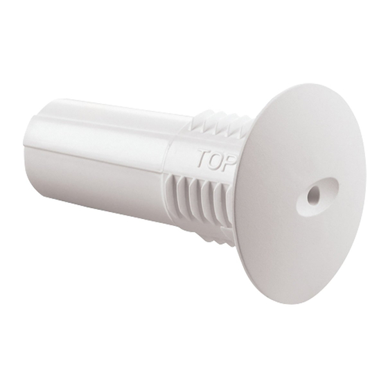
Insert the wall sleeve into the wall or ceiling.
Position the "TOP" marking to ensure the front
cover center design has either a horizontal or
vertical alignment when attached. (See
following illustration.)
•
Wire the detector.
•
Align the "TOP" markings on the detector and
wall sleeve, and insert the detector into the
wall sleeve.
APPROXIMATE
SENS1
SENS2
RANGE
7.6m (25 ft)
OFF
OFF
4.6m (15 ft)
ON
OFF
3m (10 ft)
OFF
ON
1.5m (5 ft)
ON
ON
OFF
ON
Red LED latches ON when
1, 2
detector goes into alarm
LEDs always enabled
3
)
Page 1
Wiring and Installing the Detector
•
Select either the small or large front cover and
attach it to the detector: insert the front cover
installation posts into the mounting holes and
snap the front cover into place.
Note: Both the small and large covers
provide the same excellent detection. Select
the front cover size to best fit the application.
Test Detector Installation
Enter Test Mode using an FG-701 Glassbreak
Simulator (see Testing the Detector on the next page)
or manually by shorting Test Mode pads.
Note: Testing with the FG-701 is highly
recommended.
To use the test mode pads, first remove the front cover
of the detector. Carefully slide the tip of a flat blade
screwdriver under the edge of the front cover and
gently pry upward.
Next, remove the detector from the wall sleeve. Insert
a 3mm screwdriver into the detector latch (see
Components illustration in first column). Gently press
outward, and then pull the detector toward you with the
screwdriver.
Removing detector from the Wall Sleeve
Shorting the Test Mode Pads
(if the FG-701 is unavailable)
Short the test mode pads with the screwdriver, and
check to make sure the detector is in test mode. Once
in test mode, replace the detector in the wall sleeve,
and replace front cover before testing the detector.
Advertisement
Table of Contents

Related Manuals for Honeywell IntelliSense FG-1625RFM


Summary of Contents for Honeywell IntelliSense FG-1625RFM
- Page 1 ® IntelliSense FG-1625RFM Glassbreak Detector Installation Instructions Refer to Supplemental Information (page 2) for complete descriptions of these installation steps FG-1625RFM Glassbreak Detector Set Sensitivity & LED Configuration SENS1 & SENS2 configure sensitivity FG-1625RFM with FG-1625RFM with SENSITIVITY APPROXIMATE SENS1 SENS2 Small Front Cover RANGE...
- Page 2 Page 2 ©2004 Honeywell International Inc. All rights reserved. Ê5-051-789-40CŠ Honeywell, IntelliSense and FlexGuard are registered trademarks of Honeywell International Inc. - All other brands mentioned are the trademarks or registered trademarks of their respective 5-051-789-40C 7/07 owners. Specifications subject to change without prior notice.
Need help?
Do you have a question about the IntelliSense FG-1625RFM and is the answer not in the manual?
Questions and answers