Becker AR6201 Installation & Operation Manual
Vhf-transceiver family
Hide thumbs
Also See for AR6201:
- Installation and operation manual (80 pages) ,
- Operating instructions manual (40 pages) ,
- Technical instructions (20 pages)
Table of Contents
Advertisement
AR6201
RT6201
AR6203
Becker Avionics GmbH ● Baden Airpark B108 ● 77836 Rheinmünster ● Germany
Telephone +49 (0) 7229 / 305-0 ● Fax +49 (0) 7229 / 305-217
http://www.becker-avionics.com ● e-mail: info@becker-avionics.de
RCU6201
VHF-Transceiver
Family
AR6201-(X1X)
AR6201-(X2X)
RT6201-(X10)
RT6201-(X20)
RCU6201-(X1X)
AR6203-(X1X)
AR6203-(X2X)
Software Versions:
SCI1050S305 Version 3.07
SCI1051S305 Version 1.51
and upwards
Installation
Operation
Manual
DV 14307.03
Issue 1
September 2013
Advertisement
Table of Contents

Subscribe to Our Youtube Channel
Related Manuals for Becker AR6201


Summary of Contents for Becker AR6201
- Page 1 AR6203 Installation Operation Manual DV 14307.03 Issue 1 September 2013 Becker Avionics GmbH ● Baden Airpark B108 ● 77836 Rheinmünster ● Germany Telephone +49 (0) 7229 / 305-0 ● Fax +49 (0) 7229 / 305-217 http://www.becker-avionics.com ● e-mail: info@becker-avionics.de...
- Page 3 Page No.: Date: Page No.: Date: Cover Page 09/2013 I … VIII 09/2013 1-1 … 1-20 09/2013 2-1 … 2-66 09/2013 3-1 … 3-20 09/2013 DV 14307.03 / Article Number 0638.404-071 © 2013 by Becker Avionics GmbH / All rights reserved...
- Page 5 AR6201 - RT6201 - RCU6201 - AR6203 Preface Dear Customer, Thank you for purchasing BECKER products. We are pleased that you have chosen our product and we are confident that it will meet your expectations. AR620X-(XXX) Transceivers modern family communication equipment that have comprehensive capabilities and significantly extend the typical aeronautical transceivers.
-
Page 6: Table Of Contents
AR6201 - RT6201 - RCU6201 - AR6203 Table of Contents List of Abbreviations Section 1 GENERAL DESCRIPTION Introduction Purpose of Equipment General Notes Variants Overview Short Description 1.5.1 AR6201 Single Block Transceiver 1.5.2 RT6201 Remote Transceiver 1.5.3 RCU6201 Remote Control Unit 1.5.4... - Page 7 AR6201 - RT6201 - RCU6201 - AR6203 Section 2 INSTALLATION Limitations Unpacking the Equipment and Preparation for Installation Mechanical Installation 2.3.1 AR6201 and RCU6201 Installation 2.3.2 AR6203 Installation 2.3.3 RT6201 Installation Electrical Interface 2.4.1 Connectors and Pin Assignment for AR6201, AR6203 and RT6201 2.4.2...
- Page 8 AR6201 - RT6201 - RCU6201 - AR6203 2.9.5 Installation Setup for Twin Seat with AR6201 Tandem Configuration 2-46 2.9.6 Wiring for Aircraft with Four Seats (no TANDEM) 2-48 2.9.7 Installation with RT6201 2-51 2.9.8 Aircraft with Intercom System 2-52 2.9.9...
- Page 9 AR6201 - RT6201 - RCU6201 - AR6203 Section 3 OPERATION Safety Instructions Controls and Indicators 3.2.1 Controls 3.2.2 Symbols Shown on the Display Start-Up Receive and Transmit Mode 3.4.1 Receive Mode 3.4.2 Transmit Mode Frequency Selection Modes 3.5.1 Standard Mode 3.5.2...
-
Page 10: List Of Abbreviations
AR6201 - RT6201 - RCU6201 - AR6203 List of Abbreviations AC ..Alternating Current AF ..Audio Frequency AR ..Airborne Radio ATT ..Attenuation AUX ..Auxiliary AWG ..American Wire Gauge BNC ..Bayonet Neill Concelman CBIT ... Continuous Built-In Test CFG .. - Page 11 AR6201 - RT6201 - RCU6201 - AR6203 RSSI ... Received Signal Strings Indication RT ..Remote Transceiver RX ..Receive SQL ..Squelch SPKR ... Speaker (Loudspeaker) SRC ..Source SW ..Software TSO ..Technical Standard Order TX ..Transmit VOX ..
- Page 12 AR6201 - RT6201 - RCU6201 - AR6203 Blank Page VIII DV 14307.03 Issue 1 09/2013...
-
Page 13: Section 1 General Description
Section 1 GENERAL DESCRIPTION Introduction This manual describes operation installation RCU/RT/AR6201 VHF Transceiver Family equipment. The ID label on your device shows the part number for identification purposes. Before starting to operate the unit(s) please read this manual carefully with particular attention description... -
Page 14: General Notes
(1XX) indicates only 25 kHz channel spacing capability (X1X) indicates transmit power 10W at 28V (X2X) indicates transmit power 6W at 12V (XX2) indicates white illumination color on a black panel AR6201 Single Block Transceiver (refer to Figure 1-1) Part Number Article No 8.33kHz Mode... -
Page 15: Short Description
AR6201 or AR6203 Single Block Transceiver · RT6201 Remote VHF Transceiver with controller RCU6201 For Tandem Configuration the Following Combinations apply: · AR6201 or AR6203 Single Block Transceiver with additional controller RCU6201 · RT6201 Remote VHF Transceiver with controller RCU6201 and additional second controller RCU6201... -
Page 16: Ar6201 Single Block Transceiver
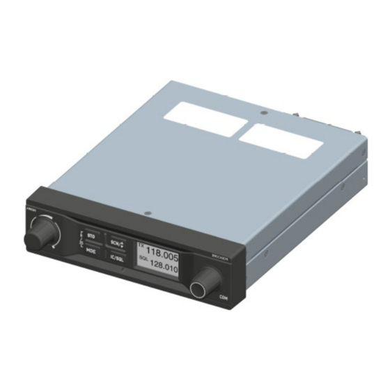
AR6201 - RT6201 - RCU6201 - AR6203 pilot and student have their own controller with full-synchronized views or as separate controllers for pilot and co-pilot. 1.5.1 AR6201 Single Block Transceiver The AR6201 Single Block Transceiver is a compact and lightweight unit designed operation cockpit environment... -
Page 17: Rcu6201 Remote Control Unit
AR6201 - RT6201 - RCU6201 - AR6203 Figure 1-2: RT6201 Remote Single Block VHF transceiver, back panel installation The RT6201 Remote Transceiver is installed by means of the attached mounting provisions and four screws (back panel installation). 1.5.3 RCU6201 Remote Control Unit The RCU6201 Remote Control Unit is a compact and lightweight unit. -
Page 18: Ar6203 Single Block Transceiver
AR6201 - RT6201 - RCU6201 - AR6203 1.5.4 AR6203 Single Block Transceiver The AR6203 Single Block Transceiver is designed as a single block unit. AR6203 is designed for operation in a cockpit environment for both general aviation aircraft and helicopters. The dimensions correspond to the state-of-the-art 160mm (6.3 “) panel mounted design. - Page 19 AR6201 - RT6201 - RCU6201 - AR6203 Displayed Frequency Operating Channel Frequency Spacing 8.33 + 25 kHz 25 kHz only (MHz) (kHz) mixed Mode Mode 118.0000 118.000 118.00 118.0000 8.33 118.005 118.0083 8.33 118.010 118.0166 8.33 118.015 118.0250 118.025 118.02 etc.
- Page 20 AR6201 - RT6201 - RCU6201 - AR6203 additional external decupling/isolation resistors. The external audio is audible only when the transceiver is in receive mode. The individual audio volume is set directly at the particular external equipment. Sidetone The sidetone is available on the headphone output during transmission.
-
Page 21: Technical Data
AR6201 - RT6201 - RCU6201 - AR6203 illumination curve (brightness to voltage relation) can be adjusted in the installation setup. LOW BATT Indication The VHF transceiver monitors power supply voltage. If the supply voltage drops below the adjustable threshold, the display indicates the message “LOW... -
Page 22: General Data
AR6201 - RT6201 - RCU6201 - AR6203 Typical Power Consumption AR620X AR620X RT6201 RT6201 RCU6201 (X2X) (X1X) (X2X) (X1X) (XXX) ≤ 0.10 ≤ 0.10 ≤ 0.10 ≤ 0.10 ≤ 0.10 Power “off” @ 12 VDC ≤ 0.10 ≤ 0.10 ≤ 0.10 ≤... -
Page 23: Dimensions & Weight
AR6201 - RT6201 - RCU6201 - AR6203 Storage Temperature range ... -55°C to +85°C Operating Temperature range .. -20°C to +55°C AR620X-(XXX) and RCU6201-(XXX) -40°C to +55°C RT6201-(XXX) short-time +70°C (all versions) Operating Altitude ... 35,000 ft Vibration ....Category S (Curve M) + Category U (Curve G) 1.7.3... -
Page 24: Transmitter Data Ar620X And Rt6201
AR6201 - RT6201 - RCU6201 - AR6203 Rated output for speaker operation .. ≥ 4 W into 4 Ohm Rated output power for headphone 1 .. ≥ 300 mW into 75 Ohm ≥ 100 mW into 600 Ohm Rated output power for headphone 2 .. ≥ 200 mW into 75 Ohm ≥... -
Page 25: Software
AR6201 - RT6201 - RCU6201 - AR6203 required to continue operation of the transceiver. This data is applicable for AR620X and RCU6201. Panel & Display Backlight ..switched off for TX Output Power ....≥ 2 W into 50 Ω (with modulation) TX Modulation Depth ..... -
Page 26: Environmental Qualification Ar620X And Rcu6201
AR6201 - RT6201 - RCU6201 - AR6203 RT6201 Remote VHF Transceiver Article Part Number EASA Approval TSO Approval Number Approval EASA. pending RT6201-(010) 0631.442-910 ETSO-2C37e TSO-C169a pending Class: D, E Class: D, E, 4, 6 RT6201-(020) 0636.312-910 ETSO-2C38e Class: 4, 6... - Page 27 AR6201 - RT6201 - RCU6201 - AR6203 Condition Section Cat. Description Temperature and Altitude -55 deg C Ground Survival Low Temperature Short-Time Operating Low 4.5.1 -20 deg C Temperature Low Operating Temperature -20 deg C High Ground Survival +85 deg C...
-
Page 28: Environmental Qualification Rt6201
AR6201 - RT6201 - RCU6201 - AR6203 Condition Section Cat. Description DC installations with Audio Freq. Conducted 18.0 battery of significant Susceptibility capacity Primary power DC or AC, Induced Signal Susceptibility 19.0 400Hz Radio Frequency Interim high intensity 20.0 Susceptibility... - Page 29 AR6201 - RT6201 - RCU6201 - AR6203 Condition Section Cat. Description Decompression 4.6.2 Overpressure 4.6.3 Temperature Variation 5 deg C per minute Humidity Standard Fixed-wing and Helicopter, Shock and Crash Safety standard Test curve M+G fixed-wing + Vibration helicopter Explosion Proofness Water Proofness 10.0...
-
Page 30: Accessories
AR6201 - RT6201 - RCU6201 - AR6203 Condition Section Cat. Description Icing 24.0 Equipment operated in an Electrostatic Discharge 25.0 aerospace environment Fire, Flammability 26.0 1.10 Accessories Available accessories 620X purchased with following Article Numbers. The connector kit or mounting kit as required for equipment installation is normally included in the delivery of your purchased Transceiver. - Page 31 AR6201 - RT6201 - RCU6201 - AR6203 Connector Kit CK5000-S (soldering version) Article-No. 0511.791-954 1 Dsub15-s Article no. 0344.801-277 1 Connector housing Article no. 0774.049-277 1 Label “COMM” Article no. 0711.111-258 1 Label “NAV” Article no. 0711.128-258 1 Label “ADF”...
- Page 32 AR6201 - RT6201 - RCU6201 - AR6203 Blank Page 1-20 DV 14307.03 Issue 1 09/2013...
-
Page 33: Section 2 Installation
The AR6201 and RCU6201 are designed to be mounted in the aircraft instrument panel within easy view and reach of pilot/operator. The mounting location for AR6201 shall be at least 30 cm away from the aircraft magnetic compass, to avoid... - Page 34 AR6201 - RT6201 - RCU6201 - AR6203 to Figure 2-1, Figure 2-2 and Figure 2-3. Leave a clearance of minimum 5 mm between the AR6201 respectively RCU6201 and other avionics to allow air circulation. Forced cooling is usually not required. For installation via back-panel mounting four screws are already attached to the unit front.
-
Page 35: Ar6203 Installation
AR6201 - RT6201 - RCU6201 - AR6203 Figure 2-3: AR6201 and RCU6201 Figure 2-4: Drilling jig for back-panel mounting; front view, dimensions in mm and dimensions in mm and (inches) (inches) 2.3.2 AR6203 Installation The AR6203 is designed to be mounted in the aircraft instrument panel within easy view and reach of pilot/operator. - Page 36 AR6201 - RT6201 - RCU6201 - AR6203 Figure 2-6: AR6203 front view, dimensions in mm and (inches) Figure 2-7: AR6203 mounting kit MK6403-1, dimensions in mm and (inches) Page 2-4 DV 14307.03 Issue 1 09/2013...
-
Page 37: Rt6201 Installation
AR6201 - RT6201 - RCU6201 - AR6203 2.3.3 RT6201 Installation The RT6201 can be installed at a suitable place on the aircraft (for example in avionics bay) or can be fixed using mounting kit MK6201-(010). The mounting location for RT6201 shall be at least 30 cm away from the aircraft magnetic compass, to avoid any interference to the magnetic compass by the transceiver. - Page 38 AR6201 - RT6201 - RCU6201 - AR6203 Figure 2-9: RT6201 mounting holes, dimensions in mm and (inches) Figure 2-10: RT6201 front view, Figure 2-11: MK6201-(010) mounting slot dimensions in mm and (inches) Page 2-6 DV 14307.03 Issue 1 09/2013...
- Page 39 AR6201 - RT6201 - RCU6201 - AR6203 Installation using Mounting Kit MK6201-(010) The necessary dimensions for installation using the mounting kit MK6201-(010) are given in Figure 2-12 (dedicated holes marked with “B” letter). Figure 2-12: MK6201-(010) mounting slot fixing holes, dimensions in mm and (inches) First secure the mounting kit frame in the aircraft, and then slide flat part X Figure 2-9 of the RT6201 into the mounting slot S (Figure 2-11).
-
Page 40: Electrical Interface
AR6201 - RT6201 - RCU6201 - AR6203 Electrical Interface 2.4.1 Connectors and Pin Assignment for AR6201, AR6203 and RT6201 Antenna Connector (Position 1) The antenna connector (Figure 2-14, position 1) is a BNC type. The antenna port is designed for operating with a nominal impedance of 50 Ohm. - Page 41 AR6201 - RT6201 - RCU6201 - AR6203 P1 Connector (System Interfaces) for AR6201, AR6203 and RT6201 The P1 connector (Figure 2-14 and Figure 2-15, Position 3) is a DSUB male connector with 25 pins and slide-in fastener. Pin No. Pin Name...
- Page 42 AR6201 - RT6201 - RCU6201 - AR6203 J1 Connector (Serial Interfaces and Discrete I/O’s) The J1 connector is a D_SUB female connector with 25 sockets and slide-in fastener. Pin No. Pin Name Direction Function J1-1 CPIN Reserved coding pin J1-2...
-
Page 43: Inputs / Outputs Detailed Description
AR6201 - RT6201 - RCU6201 - AR6203 2.4.2 Inputs / Outputs Detailed Description Microphone Connection – Standard Microphones Pin No. Pin Name Direction Function P1-8 MIKE_STD_LO Standard microphone(s) low (ground/return) used for STD1, STD2 and STD3 P1-9 MIKE_STD2_HI Standard microphone 2 high (hot) - Page 44 AR6201 - RT6201 - RCU6201 - AR6203 Note: 1. The sensitivity range of 1 mV to 20 mV was qualified under environmental conditions. For installations with high interferences it is recommended to use sensitivity level 2 mV to 20 mV.
- Page 45 AR6201 - RT6201 - RCU6201 - AR6203 Panel Illumination Pin No. Pin Name Direction Function P1-10 ILL_LO Illumination low input P1-23 ILL_HI Illumination high input The VHF transceiver provides illumination for push-buttons and LCD display. In the installation setup it can be configured if this illumination controlled via front panel or externally via pins P1-10 and P1-23 Connect ILL_LO (pin P1-10) to aircraft ground.
- Page 46 AR6201 - RT6201 - RCU6201 - AR6203 Push-To-Talk (/PTT) Pin No. Pin Name Direction Function Push-To-Talk key input 1 P1-17 /PTT1 ACTIVE state - closed contact to Push-To-Talk key input 2 J1-5 /PTT2 ACTIVE state - closed contact to There are two Push-to-Talk inputs /PTT1 and /PTT2.
- Page 47 AR6201 - RT6201 - RCU6201 - AR6203 When /ISOL is active (isolation mode) passengers are isolated from pilots intercom and from radio transmission, but still can freely communicate with each other. When /ISOL is inactive both the pilots and the passengers can hear all communications.
-
Page 48: Connector And Pin Assignment For Rcu6201
AR6201 - RT6201 - RCU6201 - AR6203 2.4.3 Connector and Pin Assignment for RCU6201 Figure 2-16: Connector on back plate of RCU6201 P1 Connector (System Interface) for RCU6201 The P1 connector ( ) is a DSUB male connector with 15 pins and Figure 2-16 slide-in fastener. -
Page 49: Installation And Configuration Of 620X Transceivers
AR6201 - RT6201 - RCU6201 - AR6203 Panel Illumination Directio Pin No. Pin Name Function P1-6 ILL_LO Illumination low input P1-8 ILL_HI Illumination high input The RCU6201 controller push-buttons and LCD display can be illuminated. The illumination can be configured in the installation setup via front panel or externally via pin P1-6/P1-8 For external configuration connect pin P1-6 to system ground and pin P1-8 to dimming voltage bus. -
Page 50: Antenna Installation
AR6201 - RT6201 - RCU6201 - AR6203 The VHF transceiver is protected internally by a 5 A resettable fuse. · Type-specific cable harnesses are also available for the aircraft wiring (contact BECKER for detailed information). · antenna cables cables should... -
Page 51: Installation Setup For Rt/Ar6201-(X1X)
AR6201 - RT6201 - RCU6201 - AR6203 Installation Setup for RT/AR6201-(X1X) The installation setup enables the avionics technician to set up the equipment configuration on ground. In-flight changes are not recommended. In most cases installation setup is started on primary controller to access controller and transceiver parameters. -
Page 52: Vu Meter
AR6201 - RT6201 - RCU6201 - AR6203 2.7.6 VU Meter The VU Meter allows correct adjustment of audio input sensitivity. Display Contents Description VU Meter is displayed on all sensitivity setting menus, it is located in the middle below the... - Page 53 AR6201 - RT6201 - RCU6201 - AR6203 Display Contents Description One of three options can be selected by turning the DIMMING INPUT NONE “ROTARY ENCODER” to dim display illumination and 0-14V push-button background lighting. Finalize 0-28V selection by pressing “STO” push-button.
- Page 54 AR6201 - RT6201 - RCU6201 - AR6203 Display Contents Description direction using the “ROTARY ENCODER”. ILLUM CURVE This parameter defines horizontal parameter V1 x (minimum values: 1.5V dimming bus and 4V for 28V dimming bus). Up to this value the brightness is zero. When reaching...
- Page 55 AR6201 - RT6201 - RCU6201 - AR6203 Display Contents Description MDE PAGES On “MDE PAGES” page three options are selectable STANDBY FREQUENCY means “ROTARY ENCODER”. three BATTERY VOLTAGE frequency selection modes provide different user CHANNEL MEMORY interfaces operating frequency selection.
- Page 56 AR6201 - RT6201 - RCU6201 - AR6203 Display Contents Description applied to pins P1-4 / pin P1-21 is audible on headphone / speaker. Note: If the auxiliary audio input is not used it is recommended to deselect “AUX INPUT”. AUX AUTO MUTE – if selected the auxiliary audio input will be muted.
- Page 57 AR6201 - RT6201 - RCU6201 - AR6203 Display Contents Description On “AUTO AUX ATT” page the attenuation for the AUTO AUX ATT auxiliary audio input can be adjusted between 0 to 40 dB by turning the “ROTARY ENCODER” When intercommunication is initiated (regardless...
- Page 58 AR6201 - RT6201 - RCU6201 - AR6203 Display Contents Description “MIC ACTIVATION” BOTH MIKES ENABLED: · input /PTT1 (Pin P1-17) activates transmission from microphone path 1 and 2 · input /PTT2 (Pin J1-5) activates transmission from microphone path 2 and path 1 ·...
- Page 59 AR6201 - RT6201 - RCU6201 - AR6203 Display Contents Description IN/OUT CFG 2 On “IN/OUT CFG 2” page the microphone inputs and MICROPHONE 1 headphone outputs for configuration CFG2 can be STD 1 MIKE STD 2 MIKE configured. This page is displayed only if MIKE_SW...
- Page 60 AR6201 - RT6201 - RCU6201 - AR6203 Display Contents Description “MIC ACTIVATION” BOTH MIKES ENABLED: · input /PTT1 (Pin P1-17) activates transmission from microphone path 1 and 2 · input /PTT2 (Pin J1-5) activates transmission from microphone path 2 and 1 ·...
- Page 61 AR6201 - RT6201 - RCU6201 - AR6203 Display Contents Description STD 1 MIKE SENS The sensitivity of standard microphone 1, “STD 1 MIKE SENS”, input is adjustable within the range 9 20 dB 150 mV mV to 1500 mV by turning the “ROTARY ENCODER”.
- Page 62 AR6201 - RT6201 - RCU6201 - AR6203 Display Contents Description Note 1: The microphone sensitivity shall be adjusted to achieve a correct modulation by keeping the cockpit noise suppression as high as possible. If the sensitivity value is very small (e.g. 10 mV) more cockpit noise will be heard than if the sensitivity value is set to a higher level (e.g.
- Page 63 AR6201 - RT6201 - RCU6201 - AR6203 Display Contents Description After modifying this parameter a communication check shall be done by the installer. It is recommended to perform this communication check with and without engine running. Note 2: Menu available on primary controller.
- Page 64 AR6201 - RT6201 - RCU6201 - AR6203 Display Contents Description SECONDARY CH If “SECONDARY CH” is selected the speaker volume will be adjustable by RCU6201. BOTH If “BOTH” is selected the speaker volume will be adjustable by the arithmetic average value from AR6201-(X0X) and RCU6201.
- Page 65 AR6201 - RT6201 - RCU6201 - AR6203 Display Contents Description sidetone attenuation “SIDETONE ATT” SIDETON ATT adjustable within the range 0…12 dB by turning the “ROTARY ENCODER”. The attenuation relates to the intercom volume. sidetone as loud as intercom signal.
- Page 66 P_RXS LOCK P_RECEIVER Used for trouble shooting and failure isolation. Note: 1. The display can only show 4 (AR6201) monitored failures types (more are available). 2. Move the slide bar via the “ROTARY ENCODER” To view any additional failures. 3. “0” means no failure were detected and stored.
-
Page 67: Factory Default Settings
AR6201 - RT6201 - RCU6201 - AR6203 Factory Default Settings R Enabled £ Disabled ˜ Selected ™ De-Selected Setting name Value DEVICE INFO DIMMING INPUT NONE BRIGHTNESS R CHANNEL STORE MEMORY OPTIONS R STORE LAST CHANNEL R STANDBY FREQUENCY MDE PAGES... - Page 68 AR6201 - RT6201 - RCU6201 - AR6203 Setting name Value MICROPHONE 2 ™ STD 1 MIKE ˜ STD 2 MIKE ™ STD 3 MIKE ™ DYN MIKE ™ NONE MIC ACTIVATION R BOTH MIKES OUTPUTS R HEADPHONE 1 ˜ HEADPHONE 2 ™...
-
Page 69: Typical Installations With Recommended Settings And Wiring Diagrams
AR6201 - RT6201 - RCU6201 - AR6203 Setting name Value RECALL DEF. Typical Installations with Recommended Settings and Wiring Diagrams 2.9.1 Single Seat Glider Installation Setup for Single Seat Glider Sub-Menu Function: / Selection “SPKR VOLUME SOURCE PRIMARY CH “IN/OUT CFG1”: “MICROPHONE 1”: NONE... - Page 70 AR6201 - RT6201 - RCU6201 - AR6203 Installation Wiring Diagrams Figure 2-19: Typical Wiring for Single Seat Glider Note: Frequency Exchange Switch and Switched Supply Relay are optional Page 2-38 DV 14307.03 Issue 1 09/2013...
- Page 71 AR6201 - RT6201 - RCU6201 - AR6203 Figure 2-20: Typical Wiring for Single Seat Glider (5-pol DIN Jack) Note: Frequency Exchange Switch is optional DV 14307.03 Issue 1 09/2013 Page 2-39...
-
Page 72: Twin Seat Motor Glider
AR6201 - RT6201 - RCU6201 - AR6203 2.9.2 Twin Seat Motor Glider Installation Setup for Twin Seat Motor Glider Sub-Menu Function: / Selection “SPKR VOLUME SOURCE BOTH “CONFIGURATION” “SWAP MIKE IC” : Disabled “IN/OUT CFG1” “MICROPHONE 1” : STD_1 MIKE (/MIKE_SW open): “MICROPHONE 2”... - Page 73 AR6201 - RT6201 - RCU6201 - AR6203 Installation Wiring Diagram Figure 2-21: Typical Wiring for Twin Seat Motor Glider DV 14307.03 Issue 1 09/2013 Page 2-41...
-
Page 74: General Aviation (Ga) Aircraft Using Standard Microphones
AR6201 - RT6201 - RCU6201 - AR6203 2.9.3 General Aviation (GA) Aircraft using Standard Microphones Installation Setup for General Aviation GA Aircraft using Standard Microphones Sub-Menu Function: / Selection “SPKR VOLUME SOURCE BOTH “CONFIGURATION” “SWAP MIKE IC” : Disabled “IN/OUT CFG1”... - Page 75 AR6201 - RT6201 - RCU6201 - AR6203 Installation Wiring Diagram Figure 2-22: Typical wiring for usage of standard hand mikes, earphones and speaker DV 14307.03 Issue 1 09/2013 Page 2-43...
-
Page 76: Installation Setup For Individual Dual Headset Configuration (Two Ic Circuit)
AR6201 - RT6201 - RCU6201 - AR6203 2.9.4 Installation Setup individual dual headset configuration (two IC circuit) Installation Setup for individual dual headset configuration (two IC circuit) Sub-Menu Function: / Selection “SPKR VOLUME SOURCE BOTH “CONFIGURATION” “SWAP MIKE IC” : Disabled “IN/OUT CFG1”... - Page 77 AR6201 - RT6201 - RCU6201 - AR6203 Installation Wiring Diagram Figure 2-23: Typical dual wiring for usage of standard hand mikes, earphones and speaker DV 14307.03 Issue 1 09/2013 Page 2-45...
-
Page 78: Installation Setup For Twin Seat With Ar6201 Tandem Configuration
AR6201 - RT6201 - RCU6201 - AR6203 2.9.5 Installation Setup for Twin Seat with AR6201 Tandem Configuration Installation Setup for Twin Seat with AR6201 Tandem Configuration Sub-Menu Function: / Selection “SPKR VOLUME SOURCE BOTH “CONFIGURATION” “SWAP MIKE IC” : Disabled “IN/OUT CFG1”... - Page 79 AR6201 - RT6201 - RCU6201 - AR6203 Installation Wiring Diagram Figure 2-24: Typical Wiring for Twin Seat with AR6201 Tandem Configuration DV 14307.03 Issue 1 09/2013 Page 2-47...
-
Page 80: Wiring For Aircraft With Four Seats (No Tandem)
AR6201 - RT6201 - RCU6201 - AR6203 2.9.6 Wiring for Aircraft with Four Seats (no TANDEM) Installation Setup for Aircraft with Four Seats (no TANDEM) Sub-Menu Function: / Selection “SPKR VOLUME SOURCE BOTH “CONFIGURATION” “SWAP MIKE IC” : Disabled “IN/OUT CFG1” (/MIKE_SW open): “MICROPHONE 1”... - Page 81 AR6201 - RT6201 - RCU6201 - AR6203 Sub-Menu Function: / Selection Remarks The external switch (connected to pin J1-24 /MIKE_SW) has the following functions: · Open: Headset 1 and 2 for pilot and copilot selected Headset 3 and 4 for passengers...
- Page 82 AR6201 - RT6201 - RCU6201 - AR6203 Installation Wiring Diagram Figure 2-25: Typical Wiring for Aircraft with Four Seats (no TANDEM) Page 2-50 DV 14307.03 Issue 1 09/2013...
-
Page 83: Installation With Rt6201
AR6201 - RT6201 - RCU6201 - AR6203 2.9.7 Installation with RT6201 RT6201 with primary controller RCU6201 used installation wirings presented above. RT6201 with RCU6201 replace AR620X. The connection between RT6201 and RCU6201 is shown in the wiring diagram below. For other equipment connection see dedicated figure above. -
Page 84: Aircraft With Intercom System
AR6201 - RT6201 - RCU6201 - AR6203 2.9.8 Aircraft with Intercom System Installation Setup for Aircraft with Intercom System Sub-Menu Function: / Selection “SPKR VOLUME SOURCE BOTH “CONFIGURATION” “SWAP MIKE IC” : Disabled “IN/OUT CFG1”: “MICROPHONE 1” : STD1_MIKE “MICROPHONE 2” : NONE “BOTH MIKES”... - Page 85 AR6201 - RT6201 - RCU6201 - AR6203 Installation Wiring Diagram Figure 2-27: Typical wiring for aircraft with Intercom System (unbalanced) DV 14307.03 Issue 1 09/2013 Page 2-53...
- Page 86 AR6201 - RT6201 - RCU6201 - AR6203 Installation Wiring Diagram Figure 2-28: Typical wiring for aircraft with Intercom System (balanced) Page 2-54 DV 14307.03 Issue 1 09/2013...
-
Page 87: Installation Setup For Twin Seat With Rt6201 Tandem Configuration
AR6201 - RT6201 - RCU6201 - AR6203 2.9.9 Installation Setup for Twin Seat with RT6201 Tandem Configuration Installation Setup for Twin Seat with RT6201 Tandem Configuration Sub-Menu Function: / Selection “SPKR VOLUME SOURCE BOTH “CONFIGURATION” “SWAP MIKE IC” : Disabled “IN/OUT CFG1”... - Page 88 AR6201 - RT6201 - RCU6201 - AR6203 Installation Wiring Diagram Figure 2-29: Typical Wiring for Twin Seat with RT6201 Tandem Configuration Note: Setup configuration only via Primary RCU Page 2-56 DV 14307.03 Issue 1 09/2013...
-
Page 89: Retrofitting An Ar4201 With An Ar620X
AR6201 - RT6201 - RCU6201 - AR6203 2.10 Retrofitting an AR4201 with an AR620X In most cases, a retrofit of the AR4201 with an AR620X will not cause any problems. However, in a few cases differences may occur due to pin incompatibility. - Page 90 AR6201 - RT6201 - RCU6201 - AR6203 AR4201 AR4201 AR6201 AR6201 Full Pin Name Function Pin Name Function compatible AF GND P1-14 Ground SPK_LO Ground MIKE STD GND Normally not used Normally not used in P1-15 AFCU LINE_OUT in installation...
-
Page 91: Dynamic Microphone Input
MIKE_DYN_HI Dynamic Mike MIKE_DYN_LO MIKE_STD_HI MIKE_STD_LO Figure 2-31: Modified dynamic microphone wiring interface for AR6201 2.10.3 Temperature Sensor The AR620X has no temperature sensor input. Remove wire from pin P1-8 and pin P1-20. 2.10.4 RS-232 Interface The AR620X has no RS-232 interface for remote control. Remove wire from pin P1-9 and pin P1-22. -
Page 92: Afcu/Agc/Afwb
AR4201, which provides supply voltage out when switched “ON” and no supply voltage when switched “OFF”. In cases where slave equipment needs to be switched ON / OFF in sync with the switching ON / OFF the AR6201-(XX) connect a relay to pin P1-24. 2.11 Post Installation Tests Note: It is assumed that the “Installation Setup”... -
Page 93: Receiver / Transmitter Operation
Power up the AR620X and tune it to a local station for a communication test. Verify that the receiver output produces a clear and readable audio and ask the local station for proper readability of the AR6201´s transmit signal. Repeat this communication test with an airborne station within ≈ 20-40 NM (Nautical Miles). - Page 94 AR6201 - RT6201 - RCU6201 - AR6203 Power the GPS and make sure that not less than 5 satellites are tracked. Check interference between VHF-COM receiver (when activated in NAV mode). Select the following channels/frequencies on the AR620X and on each frequency stay in TX and RX mode for at least 30 seconds.
-
Page 95: Flight Test Check
AR6201 - RT6201 - RCU6201 - AR6203 For the remaining avionic equipment repeat all interference checks during a flight and include all equipment not previously checked out on ground. A communication performance check in the low, mid and high frequency band of the AR620X should be included. - Page 96 AR6201 - RT6201 - RCU6201 - AR6203 Problem Possible Reason Proposed Solution Too high cabin noise The sensitivity of the Adjust the microphone during intercom / transmit microphone input is too sensitivity to a higher operation. sensitive. value to ensure the cabin noise is reduced.
-
Page 97: Continued Airworthiness
AR6201 - RT6201 - RCU6201 - AR6203 2.13 Continued Airworthiness 620X transceiver maintenance defined “on condition” only. scheduled or regular maintenance of this product is required. It is recommended to check the frequency accuracy of the airborne transceiver after 7 years. - Page 98 AR6201 - RT6201 - RCU6201 - AR6203 Blank Page 2-66 DV 14307.03 Issue 1 09/2013...
-
Page 99: Section 3 Operation
Note 2: The HMI actions described in this section can be performed on primary controller or on optional secondary RCU6201 controller. Note 3: The following graphics of the AR6201-(XXX) display content show the 8.33 kHz channel spacing for all possible operation modes. -
Page 100: Controls And Indicators
AR6201 - RT6201 - RCU6201 - AR6203 Controls and Indicators Figure 3-1: controls and indicators on AR6201 or RCU6201 3.2.1 Controls Symbol Description Main Function A ”Short press” during normal operation toggles the IC/SQL RX -SQL ON/OFF. (Intercom/Squelch) A “Long press” during normal operation activates Intercom Menu. -
Page 101: Symbols Shown On The Display
AR6201 - RT6201 - RCU6201 - AR6203 When pressing and holding down a key for at least 2 seconds, the 620X detects a “long press”. Otherwise a “short press” is assumed. If any action by the user is invalid the whole display is inverted for a short time. -
Page 102: Receive And Transmit Mode
The “TX” symbol in the left upper corner of the display indicates the AR6201- (XXX) is in transmit mode. In transmit mode several user actions such as changing frequency selection mode or channel spacing mode, which are normally allowed in receive mode, are blocked. -
Page 103: Frequency Selection Modes
AR6201 - RT6201 - RCU6201 - AR6203 No intercom operation is possible in transmit mode. The sidetone (demodulated audio of the emitted signal) is available on the headphone output. The transmit mode automatically deactivates the speaker. Note: Transmit mode is automatically terminated (return to receive mode) after 120 seconds of continuous transmitting even if PTT is still pressed. - Page 104 AR6201 - RT6201 - RCU6201 - AR6203 To change the preset frequency 1. Press the “ROTARY ENCODER“ to select the 100 MHz digits. Then rotate the “ROTARY ENCODER” clockwise/counter clockwise to change the frequency. 2. Press the “ROTARY ENCODER“ again to select the 100 kHz digits. Then rotate the “ROTARY ENCODER”...
- Page 105 AR6201 - RT6201 - RCU6201 - AR6203 To change the active frequency when in direct tune mode; 1. Press the “ROTARY ENCODER“ to select the 100 MHz digits. Then rotate the “ROTARY ENCODER” clockwise/counter clockwise to change the frequency. 2. Press the “ROTARY ENCODER“, again to select the 100 kHz digits. Then rotate the “ROTARY ENCODER”...
- Page 106 AR6201 - RT6201 - RCU6201 - AR6203 By means of channel number (CH01 to CH99 or LAST1 to LAST9) stored VHF frequencies can be selected. Then the top line shows the corresponding VHF frequency assigned to the specific channel number.
-
Page 107: Scan Mode
AR6201 - RT6201 - RCU6201 - AR6203 125.875 125.875 LAST E DS B - T E DS B - T Note: If the device is operating in the 25 kHz mode a selection of an earlier stored 8.33 kHz channel is not possible. For selection of 8.33 kHz channels, the device has to be operated in 8.33 + 25 kHz... -
Page 108: Squelch
AR6201 - RT6201 - RCU6201 - AR6203 The arrow sign now appears in front of the preset frequency and the signal is audible. A sample display shows the picture below. Note: Transmission always uses the active frequency, even if the monitored frequency is currently audible. -
Page 109: Channel Spacing Mode
AR6201 - RT6201 - RCU6201 - AR6203 Channel Spacing Mode The transceiver provides two frequency channel spacing operation modes (8.33 kHz and 25 kHz), selectable by means of pressing “STO” and “MDE” keys simultaneously for at least 2 seconds. 8.33 kHz channel spacing (left) / 25 kHz channel spacing (right) Toggling of frequency channel spacing mode is only available for AR620X-(0XX) variants. - Page 110 AR6201 - RT6201 - RCU6201 - AR6203 top line displays the active frequency and the bottom line displays the already assigned or next vacant channel number. The channel number can be selected by means of the “ROTARY ENCODER“. The label ”FREE” appears in front of “CHXX”...
-
Page 111: Automatic Storage Function
AR6201 - RT6201 - RCU6201 - AR6203 3.9.2 Automatic Storage Function transceiver contains storage function, which automatically stores recently selected VHF frequencies and updates the last channels database during operation in standard mode, direct tune mode and scan-mode. To use this function the STORE LAST CHANNEL option must be enabled in installation setup on the MEMORY OPTIONS page. - Page 112 AR6201 - RT6201 - RCU6201 - AR6203 The transceiver has two internal built in intercom circuits. Therefore up to four headsets can be connected. On the first intercom circuit the pilot and copilot are connected. When the intercom is activated the signals from the microphones are mixed and amplified to become audible on both headphone outputs.
-
Page 113: Vox & Speaker Operation
With active speaker enabled in audio configuration, the VOX is always forced “OFF” and intercom via VOX is not possible (to avoid oscillation of VOX due to acoustical feedback). The AR6201-(XXX) disables VOX if enabling speaker in active audio configuration. - Page 114 AR6201 - RT6201 - RCU6201 - AR6203 Intercom Volume Menu The active frequency is indicated in the top line of the display, while the “IC VOLUME” label and below this a bar graph with numerical value are show in the bottom line.
-
Page 115: Pilots Menu
AR6201 - RT6201 - RCU6201 - AR6203 Note: In installation with the second controller AR620X adjusts VOX threshold for Microphone 1 only while RCU6201 adjusts VOX threshold for microphone 2 only. 3.13.2 Pilots Menu Press the “MDE” key for 2 seconds to enter the pilots menu starting with BRIGHTNESS menu as first page after entering this menu. -
Page 116: Warning And Failure Indications
AR6201 - RT6201 - RCU6201 - AR6203 By turning the “ROTARY ENCODER” the squelch threshold can be adjusted: · from 6 (very weak signals are audible with high noise content; squelch opens at about -105 dBm) · to 26 (only quite strong signals are audible with low noise content;... - Page 117 AR6201 - RT6201 - RCU6201 - AR6203 Display Contents Description The transceiver has detected an internal failure during normal operation. Depending on failure reason, the device may be still operable with degraded performance or not operable at all. Possible reasons for indication: ·...
- Page 118 AR6201 - RT6201 - RCU6201 - AR6203 Blank Page 3-20 DV 14307.03 Issue 1 7/2013...
Need help?
Do you have a question about the AR6201 and is the answer not in the manual?
Questions and answers