Sign In
Upload
Manuals
Brands
tektronix Manuals
Monitor
1730 Series
tektronix 1730 Series Manuals
Manuals and User Guides for tektronix 1730 Series. We have
1
tektronix 1730 Series manual available for free PDF download: Instruction Manual
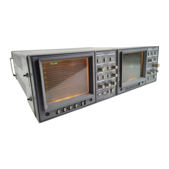
tektronix 1730 Series Instruction Manual (258 pages)
Waveform Monitor
Brand:
tektronix
| Category:
Monitor
| Size: 3 MB
Table of Contents
Instruction Manual
1
Table of Contents
5
Preface
15
Contacting Tektronix
16
Section 1 Introduction and Specification
19
Typical Configurations
20
Options
21
CRT Options
21
Power Cord Options
21
Accessories
21
Standard Accessories
21
Optional Accessories
21
Safety Information
22
Specification
22
Table 1-1: Vertical Deflection System
23
Table 1-2: DC Restoration
25
Table 1-3: Calibrator
25
Table 1-4: Horizontal Deflection System
25
Table 1-5: Synchronization
27
Table 1-6: RGB/YRGB Mode
28
Table 1-7: CRT Display
29
Table 1-8: Power Source
29
Table 1-9: Environmental Characteristics
29
Table 1-10: Certifications and Compliances
30
Table 1-11: Physical Characteristics
31
Section 2 Operating Instructions
33
Front-Panel Controls and Indicators
35
Figure 2-1: 1730-Series Front-Panel Control Locations
36
Figure 2-2: 1730-Series Rear Panel
42
Operator's Checkout Procedure
43
Figure 2-3: Equipment Connections for the 1730-Series "Operator's Checkout
44
Procedure
44
Horizontal
37
Display
38
Line Select
39
Power
39
Recall Setup
40
Miscellaneous
41
Rear-Panel Connectors
41
Bnc Connectors
41
Multi-Pin Connectors
42
Power Input
43
Figure 2-3: Equipment Connections for the 1730-Series “Operator's Checkout
46
Figure 2-4: Two-Line Color Bar Display in FLAT Filter Mode
46
Figure 2-5: Checking Vertical Gain Calibration with the 1730-Series Internal Calibrator (CAL) Reference
47
Figure 2-6: Dual Channel, 2-Line Display of Color Bar and Linearity Signals
48
Figure 2-7: Checking Timing with the Internal Calibrator Signal
49
Figure 2-8: Two-Line Display of Color Bar Signal with LOW PASS Filter on
50
Figure 2-10: Two-Line Display with Dual Filter Selected
51
Figure 2-9: Two-Line Display of Color Bar Signal with CHROMA Filter
51
Figure 2-11: Two-Line Display with LINE SELECT on
52
Figure 2-12: Two-Field Display with Intensified Line in the First Displayed Field
53
Figure 2-14: a 1-Line Sweep Rate with 15 Continuous Lines (from MID Field)
54
Figure 2-15: Display of Vertical Interval with Magnified 2 Field Sweep
54
Figure 2-16: NTSC Graticule
56
Figure 2-17: PAL Graticule
58
Dual Graticule Vertical Scales
59
Figure 2-18: Dual Standard Graticule
60
Preset Front-Panel Measurements
60
Table 2-1: Preset Front Panels
60
90 Hz (NTSC) or 100 Hz (PAL) Trigger
61
Remote Sync
61
RGB/YRGB Display
61
Horizontal Scales for NTSC and PAL Graticules
57
PAL Graticule Vertical Scales
57
Figure 2-13: Two-Field Display with 15 Line Mode of the LINE SELECT on
53
Graticules
55
NTSC Composite Video Graticule Vertical Scales
55
Service Safety Summary
63
Section 3 Installation
67
Electrical Installation
69
Power Source
69
Mains Frequency and Voltage Ranges
69
Operating Options
69
Packaging
69
Figure 3-1: Plug Jumper Locations and RGB Compensation Adjustments
70
Figure 3-2: REMOTE Connector Pin Functions
72
Table 3-2: Remote Connector Pin Assignments and Functions
72
90 Hz (100 Hz) D-2 Trigger
73
Figure 3-3: Common Parts Used to Convert from +28 VDC Enable to Ground Closure
74
RGB/YRGB Parade Display
74
AUXILIARY Connector
75
Figure 3-4: AUXILIARY Connector Pin Functions
75
Procedure for Setting RGB Offset
75
Cabinets
76
Figure 3-5: Dimensions of the 1700F00 Plain Cabinet
76
Mechanical Installation
76
Table 3-3: Auxiliary Control Pin Assignments
76
Figure 3-6: 1700F02 Portable Cabinet
77
Cabinetizing
78
Figure 3-7: Rear View of the Instrument, Shown in the Cabinet, with the Securing
78
Rack Adapter
78
Table 3-1: Internal Jumper Selections
70
REMOTE Connector
71
Figure 3-9: a 1700-Series Instrument Mounted in a 1700F05 Cabinet with a Blank
79
Figure 3-8: the 1700F05 Side-By-Side Rack Adapter
79
Custom Installation
80
Figure 3-10: a 1700F05 Side-By-Side Rack Mounting Cabinet with an Instrument
80
Figure 3-11: Considerations for Custom Installation of an Instrument
81
Section 4 Theory of Operation
83
Figure 4-1: Simplified Representation of the 1730-Series Waveform Monitor
85
Overview
85
Block Diagram
86
Circuit Blocks
86
CRT, Unblanking, and High Voltage
88
Vertical Input
88
Diagram 1
88
Channel Switch
89
Input Amplifiers
89
External Sync Input and Source Switch
90
Sync Stripper
90
Filter Selection
91
Calibrator
92
Vertical Output
92
Diagram 2
92
Gain Cell
92
2Nd DC Restorer
93
Gain Cell Amplifier
93
Switchable Gain Amplifier
93
Vertical Output Amplifier
94
Pix Monitor
95
Timing
95
Diagram 3
95
Horizontal Sync Generator
96
Field ID and Trigger Select
97
RGB Amplifier
97
Vertical Sync Generator
97
Figure 4-6: Relative Line Select Elements for the 2-Line Display
99
Figure 4-4: Simplified Representation of the AFC Phase-Lock Loop. 4-12.
99
Figure 4-5: Elements for Line Select Timing.
99
Sweep Generators and Horiz Output Diagram
100
Sweep Generator
100
Magnifier Amplifier
101
Horizontal Output Amplifier
102
Microcontroller
102
Diagram 5
102
Microprocessor
102
Diagram 6
102
Table 4-1: Control Line Functions
103
Novram
104
Switch Control
105
Focus Control
106
Z-Axis Control
106
Control Circuit Diagram 6
106
Trace Rotation
107
Graticule Illumination
107
$ 11.8 V Regulators
107
Front Panel Diagram
108
Indicators and Switches
108
Controls
108
Low Voltage Power Supply Diagram
109
Line Rectifier and Filter
109
Pulse Width Modulator
110
Output Filters
111
Error Amplifier
111
Feedback Transformer Driver and Peak Detector
111
Output Under-Voltage Shutdown
111
High Voltage Power Supply Diagram
112
HV Osc and Error Amp
112
Power Supply Outputs
112
Focus Amplifier
113
Grid Drive Circuit
113
Z-Axis Amplifier
113
Figure 4-9: Z-Axis Timing for Readout.
114
Figure 4-8: Timing Signals for 1-Line and 2-Line Sweep
114
Figure 4-10: Pinout of the CRT Socket
114
Section 5 Checks and Adjustments
115
Recommended Equipment List
117
Electrical Instruments
117
Auxiliary Equipment
119
Figure 5-1: Remote Connector for RGB
121
Figure 5-2: Remote Connector for 90/100 Triggering
122
Figure 5-3: Ten Full Cycles of Calibrator Signal between Timing Marks
129
Figure 5-4: Equipment Hook–Up for Checking Vertical Gain
132
Performance Check
123
Short-Form Procedure
123
Performance Check Procedure
126
Figure 5-5: Checking PIX MON out Signal Amplitude
134
Figure 5-6: Initial Equipment Setup to Check Flat Response
136
Figure 5-7: Adjustment Locations for the Main and Power Supply Boards
145
Figure 5-8: Segment of the Main Board, Showing the Test Points and Adjustment Locations for the +11.8 V Supplies
147
Figure 5-4: Equipment Hook-Up for Checking Vertical Gain.
134
Adjustment Procedure
143
Short-Form Procedure
143
Standard Adjustment Procedure
144
Figure 5-8: Segment of the Main Board, Showing the Test Points and Adjustment
148
Figure 5-9: Equipment Setup to Adjust 0.2 Ms Timing
148
Figure 5-10: Equipment Setup for Adjusting the Calibrator Amplitude
151
Figure 5-11: Equipment Setup for Adjusting Channel a Input Compensation
152
Figure 5-12: Adjusting for Best Flat Response
153
Figure 5-13: Using the High-Range Multiburst Signal to Set Flatness
155
Section 6 Maintenance
159
Preventive Maintenance
161
Cleaning
161
Visual Inspection
162
Static-Sensitive Components
162
Table 6-1: Static Susceptibility
162
Performance Checks and Readjustments
163
Troubleshooting
163
Foldout Pages
164
Parts Lists
165
Major Assembly Interconnection
166
General Troubleshooting Techniques
167
Specific Troubleshooting Techniques
168
Power Supply
168
Troubleshooting Procedure
168
Introduction
169
Low Volts Supply
169
Table 6-2: Power Supply Fault Symptoms
169
Table 6-3: Low Volts Supply Voltages
169
Table 6-4: Control Circuit Test Points
171
High Volts Supply
172
Table 6-5: High Volts Supply Fault Symptoms
172
Table 6-6: High Voltage Oscillator Test Points
173
Serial Port and LED Driver Diagnostics
174
Corrective Maintenance
175
Obtaining Replacement Parts
175
Mechanical Disassembly/Assembly
176
Bezel Removal
176
Graticule Light Removal and Replacement
177
Removing the Rear Panel
179
Removing the Front Panel and the Front Panel Circuit Board
179
Removing the Main Board
181
Removing the Power Supply Board
182
Repackaging
183
Identification Tag
183
Repackaging for Shipment
183
Figure 6-8: Repackaging a 1730–Series Instrument
184
Section 7 Options
185
CRT Options
187
Power Cord Options
187
Cabinets
187
Plain Cabinet (1700F00)
187
Carrying Case (1700F02)
188
Side-By-Side Rack Adapter (1700F05)
188
Blank Panel (1700F06)
188
Utility Drawer (1700F07)
188
Ordering
188
Section 8 Replaceable Electrical Parts
189
Parts Ordering Information
191
Using the Replaceable Electrical Parts List
191
Cross Index-Mfr. Code Number to Manufacturer
191
Replaceable Electrical Parts
191
Column Descriptions
192
Cross Index – Mfr. Code Number to Manufacturer
193
Section 9 Diagrams/Circuit Board Illustrations
223
Section 10 Replaceable Mechanical Parts
249
Parts Ordering Information
249
Using the Replaceable Mechanical Parts List
249
Abbreviations
249
Chassis Parts
249
Column Descriptions
250
Qty (Column 5)
250
Name and Description (Column 6)
250
Mfr. Code (Column 7)
250
Mfr. Part Number (Column 8)
250
Cross Index – Mfr. Code Number to Manufacturer
251
Replaceable Mechanical Parts
252
Advertisement
Advertisement
Related Products
Tektronix 1735 HD
Tektronix 1740A/1750A
Tektronix 1705A
Tektronix 1750A Series
Tektronix 1751A
Tektronix 1755A
Tektronix 1750 Series
Tektronix 1751
Tektronix 1741A
Tektronix 1765
tektronix Categories
Test Equipment
Measuring Instruments
Amplifier
Portable Generator
Printer
More tektronix Manuals
Login
Sign In
OR
Sign in with Facebook
Sign in with Google
Upload manual
Upload from disk
Upload from URL