Table of Contents
Advertisement
Quick Links
Download this manual
See also:
User Manual
S
C
UPERMICR
ONTACT
R
• Website: www.supermicro.com
X10DR
/X10DR
-T
• General Information: marketing@supermicro.com
I
I
• Tech Support: support@supermicro.com
Q
R
G
Rev. 1.0a
UICK
EFERENCE
UIDE
• Phone: +1 (408) 503-8000, Fax: +1 (408) 503-8008
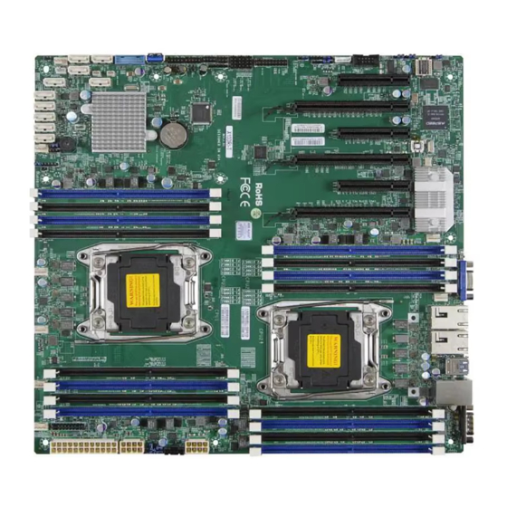
Motherboard Layout and Features
UID
JUIDB1
BMC
LAN CTRL
LEDM1
BIOS
X10DRi-(T)
Rev. 1.02
T-SGPIO1
T-SGPIO2
T-SGPIO3
J23
Battery
Intel PCH
SP1
JSD2
JOH1
JSD1
I-SATA0
CPU Installation
Heatsink Installation
Socket Keys
Screw #1
CPU Keys
Note: Graphics shown in this quick reference guide are for illustration only. Your components may or may not look exactly the same as the drawings shown in this
I
NFORMATION
USB6/7(3.0)
USB0/1
(2.0)
COM1
VGA
Fan5
IPMI_LAN
LAN2
LAN1
CLOSE 1st
CPU2
OPEN 1st
CLOSE 1st
CPU1
OPEN 1st
= mounting hole
Front Panel Control (JF1)
Screw #4
Screw #2
20
19
Ground
NMI
X
X
FP PWRLED
3.3 V
HDD LED
UID Switch
NIC1 Link LED
NIC1 Activity LED
Screw #3
NIC2 Activity LED
NIC2 Link LED
OH/Fan Fail/
UID LED
PWR Fail LED)
Power Fail LED
3.3V
Reset
Reset Button
Ground
Power Button
Mounting Holes
Ground
PWR
2
1
guide.
F
,
OR YOUR SYSTEM TO WORK PROPERLY
PLEASE DOWNLOA D APPROPRIATE
/
/
'
DRIVERS
IMAGES
USER
S MANUAL FROM THE LINKS BELOW
• Manuals: http://www.supermicro.com/support/manuals/
• Drivers & Utilities:
ftp://ftp.supermicro.com/
• Safety:
http://
www.supermicro.com/about/policies/safety_information.cfm
Jumpers and Connectors
Jumpers
Jumper
Description
Default Setting
JBT1
Clear CMOS
See Chapter 3
JI
2
C1/JI
2
C2
SMB to PCI-E Slots
Pins 2-3 (Disabled)
JPB1
BMC Enable
Pins 1-2 (Enabled)
JPG1
VGA Enable
Pins 1-2 (Enabled)
GLAN1/GLAN2 Enable (X10DRi)
JPL1
Pins 1-2 (Enabled)
(10G) TLAN1/TLAN2 Enable (X10DRi-T)
JPME2
Manufacture (ME) Mode Select
Pins 1-2 (Normal)
JWD1
Watch Dog Timer Enable
Connectors
Pins 1-2 (Reset)
Connectors
Description
Battery
Onboard CMOS Battery (See Chpt. 3 for Used Battery Dis-
posal)
COM1/COM2
Backplane COM Port1/Front Accessible COM2 Header
Fan1-6, FanA-B
CPU/System Fan Headers
J24
24-pin ATX Main Power Connector (See Warning on Pg. 1-6.)
JD1
Speaker/Power LED
JF1
Front Panel Control Header
JIPMB1
4-pin External BMC I
C Header (for an IPMI Card)
2
JL1
Chassis Intrusion
JOH1
Overheat LED Indicator
JPI
2
C1
Power Supply SMBbus I
2
C Header
JPWR1/2
12V 8-Pin Power Connectors (See Warning on Pg. 1-6.)
JSD1/JSD2
SATA DOM (Device on Module) Power Connectors
JSTBY1
Standby Power Connector
JTPM1
TPM (Trusted Platform Module)/Port 80 Header
JUIDB1
LAN1/LAN2
G-bit Ethernet (GLAN) Ports 1/2 (X10DRi)
10G-bit Ethernet (TLAN) Ports 1/2 (X10DRi-T)
(IPMI) LAN
IPMI_Dedicated LAN support by the Aspeed controller
(I-)SATA 0-5
SATA 3.0 Connectors supported by Intel PCH (I-SATA 0-5),
(I-SATA4/I-SATA5: can be used as Supermicro SuperDOM
(Disk-on-Module) devices with built-in power connectors)
(S-)SATA 0-3
SATA 3.0 Connectors supported by Intel PCH (S-SATA 0-3)
(CPU1) Slot1
PCI-Express 3.0 x8 Slot from CPU1
(CPU1) Slot2
PCI-Express 3.0 x16 Slot from CPU1
(CPU1) Slot3
PCI-Express 3.0 x8 Slot from CPU1
(CPU2) Slot4
PCI-Express 3.0 x16 Slot from CPU2
(CPU2)Slot5
PCI-Express 3.0 x8 Slot from CPU2
(CPU1)Slot6
PCI-Express 3.0 x16 Slot from CPU2
(T-)SGPIO1/2/3
Seria_Link General Purpose I/O Headers 1/2/3 (for SATA
ports), (T-SGPIO1 for I-SATA0-3, T-SGPIO2 for I-SATA4/5, T-
SGPIO3 for S-SATA0-3)
SP1
Internal Speaker/Buzzer
(BP) USB 0/1
Backpanel USB 2.0 Ports 0/1
(BP) USB 6/7
Backpanel USB 3.0 Ports 6/7
(FP) USB 2/3, 4/5
Front Accessible USB 2.0 Connection Headers 2/3 (J25), 4/5
(J27)
(FP) USB 10
Front Panel Accessible Type A 3.0 Connector USB10 (J26)
(FP) USB 8/9
Front Panel Accessible Vertical USB 3.0 Connector for USB
8/9 (J-USB3-1AA)
VGA
Backpanel VGA Port
LED Indicators
LED
Description
State
Status
LE1
Rear UID LED
Blue: On
LE2
Onboard PWR LED
On
System Power On
LEDM1
BMC Heartbeat LED
Green: Blinking
BMC Normal
Note: Refer to Chapter 1 of the user manual for detailed information on jumpers, connectors,
and LED indicators.
P
C
ACKAGE
ONTENTS
:
• One (1) Supermicro Motherboard
• Six (6) SATA Cables (CBL-0044L)
• One (1) I/O Shield (MCP-260-00042-0N)
• One (1) Quick Reference Guide (MNL-1491-QRG)
CPU Support
Dual Intel
®
E5-2600v3/v4 Series Processors (Socket R3-LGA 2011);
each processor supports dual full-width Intel QuickPath Interconnect (QPI) links
(of up to 9.6 GT/sone direction per QPI)
Memory Support
The X10DRi/X10DRi-T Motherboard supports up to 2048 GB of Load Reduced
(LRDIMM) or 512 GB of Registered (RDIMM) DDR4 (288-pin) ECC 2400 MHz (max.)
modules in 16 slots. Memory speed support depends upon the CPUs installed in the
motherboard. For the latest memory updates, please refer to our website at
http://www.supermicro.com/products/motherboard.
Populating RDIMM/LRDIMM DDR4
Memory Modules for the E5-2600v3-
based Motherboard
1 Slot Per
2 Slots Per Channel
Channel
1DPC
1DPC
2DPC
1.2V
1.2V
1.2V
2133
2133
1866
2133
2133
1866
2133
2133
1866
2133
2133
1866
2133
2133
2133
2133
2133
2133
†
DIMM Memory Installation
1
Back Panel I/O Connectors
4
1
3
2
Backplane I/O Panel
1.
COM Port 1
2.
Back Panel USB 2.0 Port 0
3.
Back Panel USB 2.0 Port 1
4.
IPMI_Dedicated LAN
5.
Back Panel USB 3.0 Port 6
Populating RDIMM/LRDIMM DDR4
Memory Modules for the E5-2600v4-
based Motherboard
Speed (MT/s); Voltage (V);
Slot Per Channel (SPC) and DIMM Per
Channel (DPC)
DIMM Capacity
Ranks Per
1 Slot Per
(GB)
DIMM and
2 Slots Per Channel
Type
Channel
Data
Width
1DPC
1DPC
2DPC
4Gb
8Gb
1.2V
1.2V
1.2V
RDIMM
SRx4
8GB
16GB
2400
2400
2133
RDIMM
SRx8
4GB
8GB
2400
2400
2133
RDIMM
DRx8
8GB
16GB
2400
2400
2133
RDIMM
DRx4
16GB
32GB
2400
2400
2133
LRDIMM
QRx4
32GB
64GB
2400
2400
2400
LRDIMM
8Rx4
64GB
128GB
2400
2400
2400
3DS
Notches
Release Tabs
6
5
7
8
9
6. Back Panel USB 3.0 Port 7
7. Gigabit LAN 1 (X10DRi), (10G)
TLAN 1 (X10DRi-T)
8. Gigabit LAN 2 (109DRi), (10G)
TLAN 2 (X10DRi-T)
9. Back Panel VGA
Advertisement
Table of Contents


Need help?
Do you have a question about the X10DRI-T and is the answer not in the manual?
Questions and answers