Table of Contents
Advertisement
Advertisement
Table of Contents

Subscribe to Our Youtube Channel
Related Manuals for Magnum CSW1012


Summary of Contents for Magnum CSW1012
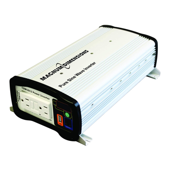
- Page 1 CSW1012 Pure Sine Wave Inverter Owner’s Manual...
-
Page 2: Contact Information
If the CSW1012 inverter fails, it is reasonable to assume that the health of the user or other persons may be endangered. -
Page 3: Safety Symbols
• Increase the separation between the equipment and the receiver. • Connect the equipment to an outlet on a circuit different from that to which the receiver is connected. • Consult the dealer or an experienced radio/TV technician for help. © 2013 Magnum Energy, Inc. -
Page 4: Table Of Contents
Table 2-1, DC Wire/Overcurrent Device for Rated Use ......9 Table 2-2, Appliance Power Consumption and Run Time ......11 Table 3-1, Examples of Digital Display Readings ........15 Table 4-1, CSW1012 Inverter Error Codes ........... 17 Table 4-2, Troubleshooting Guide ............17 Table 5-1, CSW1012 Specifications ............ 18... -
Page 5: Overview
Please read this chapter to familiarize yourself with the features and benefi ts of your CSW1012 inverter. Figure 1-1, Front Panel Features The front panel of the CSW1012 inverter is equipped with the following features: Status Indicator – an at-a-glance LED that provides the inverter’s sta- tus—lights green, red, or amber (see Section 4.0 Operation). -
Page 6: Figure 1-2, Back Panel Features
Figure 1-2, Back Panel Features Regulatory Compliance The CSW1012 inverter is intended to be used for land vehicles (RVs or trucks) or marine craft. It has been tested and listed to UL 458, 5th Edition (Power Converters/Inverters and Power Converter/Inverter Systems for Land Vehicles and Marine Crafts) for use in the US;... -
Page 7: 2.0 Installation
Pre-Installation Before proceeding, read the entire Installation section to determine how best to install your CSW1012 inverter. The more thorough you plan in the beginning, the better your inverter needs will be met. The simplifi ed system diagram shown in Figure 2-1 should be reviewed to assist you in planning and designing your installation. -
Page 8: Figure 2-1, Basic System Diagram
AC IN Breaker: 15A max) AC OUT CSW1012 Inverter Sub-Panel Ground Outlet (Vehicle chassis, Disconnect DC ground bus, or engine negative bus) AC Loads Fuse (15A max) Tools Battery Bank Figure 2-1, Basic System Diagram © 2013 Magnum Energy, Inc. -
Page 9: Locating And Mounting The Inverter
Accessible – Do not block access to the front or back of the inverter. Allow enough room to clearly view the digital display and to access the AC and DC wiring connections—they will need to be checked and tightened periodically. See Figure 2-3 for the CSW1012 inverter’s dimensions. © 2013 Magnum Energy, Inc. -
Page 10: Mounting The Inverter
Review the information in this section before mounting the inverter. Orientating the Inverter When mounted indoors, the CSW1012 inverter can be mounted on/underneath a horizontal surface (shelf or table) or on a vertical surface (wall or bulkhead) with the DC terminals facing left, right, or up—do not mount with the DC terminals facing downward (see Figure 2-2). -
Page 11: Csw1012 Inverter Dimensions
2.0 Installation 2.2.3 CSW1012 Inverter Dimensions Use the dimensions in Figure 2-3 to assist in mounting the CSW1012 inverter. Front " (8.9 cm) (AC side) " (16.5 cm) " 5/16 (26.2 cm) " (32.1 cm) " (29.5 cm) Back (DC side) 7"... -
Page 12: Wiring The Inverter - General Requirements
Wiring the Inverter – General Requirements This section describes the requirements and recommendations for wiring the CSW1012 inverter. Before wiring the inverter, carefully read all instructions. WARNING: Wiring should meet all local codes/standards and be performed by qualifi ed personnel (i.e., licensed electrician). -
Page 13: Dc Wire Sizing
Wire Size* #2 AWG (33.6 mm 150 amps #2 AWG CSW1012 [170 amps] with time delay (33.6 mm * Copper wire rated with 75°C (167°F) insulation at an ambient temperature of 30°C (86°F) in free air. © 2013 Magnum Energy, Inc. -
Page 14: Dc Overcurrent Protection
2,700 amps or less, then an ANL type of fuse may be used—if in doubt, use a Class-T fuse. See Table 2-1 for the fuse size (coordinated with the DC wire size) recommended for the CSW1012. 2.4.3 DC Grounding The inverter should always be connected to a permanent, grounded wiring system. -
Page 15: Wiring The Battery Bank
2.4.6 Appliances and Run Time The CSW1012 inverter can power a wide range of household appliances including small motors, hair dryers, clocks, and other electrical devices. As with any appliance using batteries for power, there is a certain length of time that it can run—this is called “run time.”... -
Page 16: Wiring The Inverter To The Battery Bank
DC chassis ground screw (Item 12, Figure 1-2) to a dedicated system ground. It is recommended that you connect the cable to the chassis ground screw with a copper, tin-plated © 2013 Magnum Energy, Inc. -
Page 17: Figure 2-4, Dc Cable To Battery Terminals
#12 Flat washer DC cable with ring lug Inverter’s DC + terminal CSW1012 CAUTION: Inverter Ensure nothing is placed between the DC terminal and the ring lug. Figure 2-5, DC Cable to Inverter’s DC Terminals © 2013 Magnum Energy, Inc. -
Page 18: Testing The Inverter
Note: If the bulb remains lit or the RESET button does not pop out, the GFCI may not be functioning properly. Press the RESET button. The AC load should come back on (bulb lights again). © 2013 Magnum Energy, Inc. -
Page 19: 3.0 Operation
3.0 Operation Operation The CSW1012 inverter uses a front panel that contains a power/select button, a status indicator, a digital display for viewing system status, a remote port, a USB port, and a GFCI AC output receptacle. Power/Select Button The Power/Select button is used to turn the inverter on and off. To turn the unit on, press and hold the button for 1 second until you hear a “beep”. -
Page 20: Understanding Loads
Running several loads at once – Sometimes the total surge requirement of all the loads is higher than the CSW1012 inverter can deliver. You may want to turn them on individually to ensure that the inverter does not have to deliver the starting current for all the loads at once. -
Page 21: Troubleshooting
4.0 Troubleshooting Troubleshooting Use Table 4-1 below to determine what condition triggered the error/warning code on the unit’s digital display, and what corrective action is needed. Table 4-1, CSW1012 Inverter Error Codes Code Condition Corrective Action Unit has sensed the input is Immediately recharge the voltage is low (<10.5 VDC) -
Page 22: Specifi Cations
5.0 Specifi cations Specifi cations Table 5-1, CSW1012 Specifi cations Electrical Specifi cations – AC Output Continuous power* 1,000 Watts Surge power (peak)** 2,000 Watts (10 sec)** 1,000 - 1,500 Watts (1 sec)** 1,500 - 2,000 Watts (0.2 sec)** >2,000 Watts AC output voltage (@12.5VDC) -
Page 23: Limited Warranty
6.0 Service and Warranty Info Limited Warranty Magnum Energy, Inc., warrants the CSW1012 inverter to be free from defects in material and workmanship that result in product failure during normal us- age, according to the following terms and conditions: The limited warranty for this product extends for a maximum of 12 months from the product’s original date of purchase. - Page 24 Magnum Energy, Inc. 2211 West Casino Rd. Everett, WA 98204 Phone: 425-353-8833 Fax: 425-353-8390 Web: www.magnumenergy.com PN: 64-0063 Rev A...
Need help?
Do you have a question about the CSW1012 and is the answer not in the manual?
Questions and answers