Magnum CSW412 Owner's Manual

Magnum CSW412 Owner's Manual

Pure sine wave inverter csw series
Table of Contents

Advertisement

CSW Series
Pure Sine Wave Inverter
Owner's Manual

Advertisement

Table of Contents
loading

Summary of Contents for Magnum CSW412

  • Page 1 CSW Series Pure Sine Wave Inverter Owner’s Manual...
  • Page 2: Contact Information

    Thank you from all of us at Sensata Technologies for purchasing this CSW Series inverter. The CSW Series includes the CSW412, CSW1012 and CSW2012 inverters; all under the Magnum-Dimensions brand from Sensata Technologies. We understand that you have many purchasing options in the marketplace and are pleased that you have decided on this product.
  • Page 3: Safety Symbols

    IMPORTANT PRODUCT SAFETY INSTRUCTIONS This manual contains safety instructions that must be followed during the installation and operation of this product. Read all instructions and safety information on the inverter and in this manual before installing or using. Safety Symbols To reduce the risk of electrical shock, fi...
  • Page 4: Table Of Contents

    Table of Contents 1.0 Introduction ................1 1.1 Features - CSW1012 and CSW2012 ..........1 1.2 Features - CSW412 ..............3 1.3 Regulatory Compliance .............. 4 2.0 Installation ................5 2.1 Pre-Installation ................ 5 2.1.1 Installation Guidelines ............5 2.1.2 Unpacking and Inspection ........... 5 2.1.3 Tools Required ..............
  • Page 5 
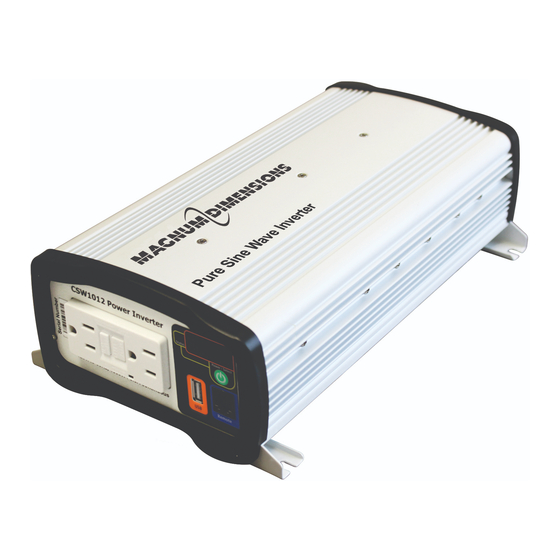
Figure 1-1, Front Panel Features (CSW1012 and CSW2012) ....1 Figure 1-2, Back Panel Features (CSW1012).......... 2 Figure 1-3, Back Panel Features (CSW2012).......... 2 Figure 1-4, Front Panel Features (CSW412) ........... 3 Figure 1-5, Back Panel Features (CSW412) ........... 4 Figure 2-1, Basic System Diagram ............6 Figure 2-2, RV OEM System Diagram ...........
  • Page 6: 1.0 Introduction

    Introduction Congratulations on your purchase of the CSW Series pure sine wave inverter. The CSW Series includes the CSW412, CSW1012 and CSW2012 inverters; under the Magnum-Dimensions brand from Sensata Technologies. The CSW Series inverters are “pure” sine wave inverters designed to be powerful, yet simple to operate, and will provide you with reliable AC power for trouble-free use.
  • Page 7: Figure 1-2, Back Panel Features (Csw1012)

    1.0 Introduction The back panels of the CSW1012 and CSW2012 inverters are equipped with the following features (See Figure 1-2 and Figure 1-3): Cooling Fan(s) – an intake cooling fan that automatically turns on when the inverter’s internal temperature rises above 122°F (50°C). The fan turns off when the inverter’s internal temperature falls below 122°F (50°C).
  • Page 8: Features - Csw412

    1.0 Introduction Features - CSW412 The CSW412 inverter is equipped with the following front panel features (see Figure 1-4): Power Indicator – an at-a-glance LED that lights green when the inverter is on. (see Section 3.0 Operation). Fault Indicator – an at-a-glance LED that comes on to indicate an inverter fault (see Section 4.0 for troubleshooting).
  • Page 9: Regulatory Compliance

    10. Mounting Flanges (front and rear) – used to mount and secure the inverter to a shelf/wall. 11. Model Number – the model number of the inverter (i.e., CSW412), and regulatory compliance information. 12. DC Positive Terminal (red) – the inverter’s connection to the positive terminal on the 12 VDC battery bank.
  • Page 10: 2.0 Installation

    CSW Series inverter • CSW Series Owner’s Manual If items appear to be missing or damaged, contact your authorized Magnum- Dimensions dealer or Magnum-Dimensions directly. *** Save your proof-of-purchase as a record of your ownership; it is needed if the unit should require in-warranty service. *** 2.1.3...
  • Page 11: Figure 2-1, Basic System Diagram

    2.0 Installation AC Source (120VAC, 60 Hz Sinewave) Main Panel (Branch Circuit Breaker to Transfer Switch: 15A max) CSW-TS15 Transfer Switch AC IN AC OUT CSW Series Inverter Sub-Panel Disconnect Outlet Ground (Vehicle chassis, DC ground bus, AC Loads or engine (15A max) negative bus) Fuse...
  • Page 12: Figure 2-2, Rv Oem System Diagram

    2.0 Installation AC Source (120VAC, 60 Hz Sinewave) Main Panel (Branch Circuit Breaker to Transfer Switch: 15A max) CSW-TS15 Transfer Switch AC IN Dedicated AC Load AC OUT (15A max) CSW Series Notes: The NEC requires overcurrent Inverter protection for wiring and equipment in both AC and DC circuits.
  • Page 13: Locating And Mounting The Inverter

    (wall or bulkhead) with the DC terminals facing left or right. Additionally, the CSW1012 and CSW2012 can be mounted with the DC terminals facing up (CSW412 cannot be mounted with terminal’s facing up or down)—do not mount with the DC terminals facing downward (see Figure 2-3).
  • Page 14: Figure 2-3, Approved Mounting Positions

    For RV Installation: Mount flat on a horizontal surface only Figure 2-3, Approved Mounting Positions 5.8’’ (14.7 cm) 7.9’’ (20 cm) Front (AC Side) Back (DC Side) 3.4’’ (8.7 cm) Figure 2-4 CSW412 Dimensions © 2015 Sensata Technologies...
  • Page 15: Figure 2-5 Csw1012 Dimensions

    2.0 Installation 10.3’’ (26.2 cm) 12.6’’ (32.1 cm) Front (AC Side) Back (DC Side) 3.4’’ (8.4 cm) Figure 2-5 CSW1012 Dimensions 13.4’’ (34 cm) 16.5’’ (41.9 cm) Back (DC Side) Front (AC Side) 3.5’’ (8.9 cm) Figure 2-6 CSW2012 Dimensions ©...
  • Page 16: Wiring The Inverter - General Requirements

    Inverter Torque Torque Wrench Model Terminals Requirements Size Needed Hex Cap 52 to 58 lbf-in CSW412 12 mm wrench screws (5.9 to 6.5 N-m) M6 x 1.0 79 to 96 lbf-in CSW1012 10 mm wrench Hex nuts (8.9 to 10.9 N-m) M8 x 1.25...
  • Page 17: Dc Wiring

    (1/4”) bolt hole to connect the DC wires to the inverter’s DC terminals. • The battery bank voltage MUST be between 10.5-15.5 (10.5 - 15.75 for the CSW412) for the inverter to operate. If the voltage exceeds 16.0V, the inverter may be damaged. •...
  • Page 18: Dc Wire Sizing

    (as shown in Figure 2-2), and the inverter and dedicated load have been thoroughly tested and sold together by the OEM as a complete system. Table 2-2, DC Wire/Overcurrent Device for Rated Use Inverter Model CSW412 CSW1012 CSW2012 Full Load C urrent 38 amps...
  • Page 19: Dc Overcurrent Protection

    2.0 Installation 2.4.2 DC Overcurrent Protection For safety reasons and to comply with electrical code regulations, DC overcurrent protection must be provided as part of the installation. The DC overcurrent protection device must be installed in the positive DC cable line, it can be a fuse (with a disconnect switch) or a circuit breaker and must be DC-rated.
  • Page 20: Wiring The Battery Bank

    2.0 Installation 2.4.5 Wiring the Battery Bank WARNING: Lethal currents will be present if the positive and negative cables attached to the battery bank touch each other. During the installation and wiring process, ensure the cable ends are insulated or covered to prevent touching/shorting the cables. Info: DO NOT connect the DC wires from the battery bank to the inverter until 1) all DC wiring is complete, 2) the correct DC overcurrent protection has been installed, and 3) the correct DC...
  • Page 21: Wiring The Inverter To The Battery Bank

    2.0 Installation 2.4.7 Wiring the Inverter to the Battery Bank CAUTION: The inverter is NOT reverse polarity protected—if positive terminal of the battery is connected to the negative terminal of the inverter and vice versa, severe damage to the inverter will occur and this will void the warranty.
  • Page 22: Figure 2-7, Dc Cable To Battery Terminals

    2.0 Installation DC cable with ring lug lock washer BATTERY battery terminal flat washer Verify that the bolt battery DC cable lugs are flush post with the battery terminals. Figure 2-7, DC Cable to Battery Terminals M6-1.0 hex nut lock washer #12 flat washer DC cable with ring lug...
  • Page 23: Testing The Inverter

    GFCI’s outlet, and follow these steps to test the installation and the inverter’s operation. • CSW412 inverters: Toggle the ON/OFF Power Switch to the ON (I) position to turn the unit on. The Power Indicator will turn on to indicate that the AC output power is available.
  • Page 24: 3.0 Operation

    (i.e., AC loads) connected to the inverter’s output. CSW412 Operation The CSW412 inverter uses a front panel that contains a power on/off switch, two LED indicators, a USB port, and a GFCI AC output receptacle. Turning the Inverter on and off The ON/OFF Power switch is used to turn the inverter on and off.
  • Page 25: Csw1012 And Csw2012 Operation

    3.0 Operation CSW1012 and CSW2012 Operation The CSW1012 and CSW2012 inverters use a front panel that contains a power/select button, a status indicator, a digital display for viewing system status, a remote port, a USB port, and a GFCI AC output receptacle. Turning the Inverter on and off The Power/Select button is used to turn the inverter on and off.
  • Page 26: Understanding Loads

    3.0 Operation Understanding Loads The inverter can power most loads within its power rating, however, there are special conditions that can cause a load to behave differently than expected. Following are some common problems encountered when using this inverter. USB loads – When using the USB connector, be sure that the device you will be connecting will accept 5 volts (≤...
  • Page 27: 4.0 Troubleshooting

    4.0 Troubleshooting Troubleshooting Use Table 4-1 to troubleshoot your inverter. For CSW1012 or CSW2012 inverters, also use Table 4-2 to view the unit’s digital display to determine what condition triggered the error/warning code and what corrective action is needed. Table 4-1, Troubleshooting Guide Problem Symptom Solution...
  • Page 28: Specifi Cations

    5.0 Specifi cations Specifi cations Table 5-1, CSW Series Specifi cations CSW412 CSW1012 CSW2012 Model Electrical Specifi cations Continuous Power 400 W 1000 W 2000 W Surge Power (Peak) 800 W 2000 W 4000 W AC Output Voltage (12.5V) 120 VAC RMS ± 5% AC Output Current 3.3 AAC...
  • Page 29: Limited Warranty

    • the product was not installed/operated according to instructions. How to Receive Warranty Service If your product requires warranty service, contact Sensata (Magnum- Dimensions) at: • Telephone: 425-353-8833, or •...
  • Page 30 Magnum-Dimensions Products Manufactured by: Sensata Technologies 2211 West Casino Rd. Everett, WA 98204 Phone: 425-353-8833 Fax: 425-353-8390 Web: www.Magnum-Dimensions.com PN: 64-0063 Rev C...

This manual is also suitable for:

Csw1012Csw2012

Table of Contents