Sign In
Upload
Download
Table of Contents
Contents
Add to my manuals
Delete from my manuals
Share
URL of this page:
HTML Link:
Bookmark this page
Add
Manual will be automatically added to "My Manuals"
Print this page
×
Bookmark added
×
Added to my manuals
Manuals
Brands
Magnum Manuals
Inverter
MMG25FHI
Operating manual
Magnum MMG25FHI Operating Manual
Diesel generator
Hide thumbs
Also See for MMG25FHI
:
Operating manual
(60 pages)
1
2
Table Of Contents
3
4
5
6
7
8
9
10
11
12
13
14
15
16
17
18
19
20
21
22
23
24
25
26
27
28
29
30
31
32
33
34
35
36
37
38
39
40
41
42
43
44
45
46
47
48
49
50
51
52
53
54
55
56
page
of
56
Go
/
56
Contents
Table of Contents
Troubleshooting
Bookmarks
Table of Contents
Introduction
Table of Contents
Safety Notes
Operating Safety
Engine Safety
Electrical Safety
Towing Safety
Reporting Trailer Safety Defects
Safety Symbol Summary
Specifications
Unit Dimensions
Unit Serial Number Locations
Component Locations
Main Control Panel Features - Mmg 25Fhi, 35Fh, 35Fhp, 50Fhp, 55Fh
Main Control Panel Features - Mmg 45Fhk
Magnum Digital Controller (MDC)
Digital Controller Features and Functions
Generator Monitoring
Engine Monitoring
Fine Voltage Adjustment
Front Hood Operation
Rear Hood Operation
Rear Hood Operation, Continued
Pre - Start Check List
Manual Starting of the Generator
Auto" (Remote) Starting of the Generator
Shutting down the Generator
MDC Controller Information Displays, Functions and Reset
Magnum Digital Controller (MDC) - Generator Operational Status
Magnum Digital Controller (MDC) - Alarm Management
Magnum Digital Controller (MDC)- List of Possible Alarms/Descriptions
Mmg Engine Controller
Adjusting the Display Back Lighting
MDC Controller (MDC) - History
Resetting of the "Time to Service" Reminder
Troubleshooting Automatic Shut down Conditions
Generator Output Connection Lugs
Generator Cam Lock Connections (Optional)
Voltage Selector Switch
4-Position Voltage Selector Switch (Optional)
Emergency Stop Switch
Main Circuit Breaker
Voltage Regulation
Customer Convenience Outlets
Derating for Altitude
Remote Start Terminal Block
Engine Break-In Requirements
Daily Walk Around Inspection
John Deere Engines Only
Engine and Generator Maintenance
Daily Maintenance Checks
Lifting the Generator
Towing the Trailer
Trailer Wheel Bearings
Auxiliary Fuel Tank Option
Fuel Transfer Pump Option
Checking Generator Drive Plate Torque
Trailer Wiring Diagram
Electric Brake Wiring Harness
Ac Wiring Diagram
Ac Wiring Diagram: Mmg45Fhk
Ac Wiring Diagram: 4-Position Voltage Selector Switch
DC Wiring Diagram - Isuzu
DC Wiring Diagram - John Deere
DC Wiring Diagram - Perkins
DC Wiring Diagram - Kubota
Service Log
Advertisement
Quick Links
1
Specifications
2
Main Control Panel Features - Mmg 25Fhi, 35Fh, 35Fhp, 50Fhp, 55Fh
3
John Deere Engines Only
4
DC Wiring Diagram - John Deere
Download this manual
See also:
Operating Manual
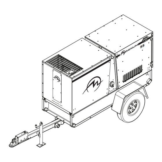
DIESEL GENERATOR
MMG25FHI • MMG35FH • MMG35FHP
MMG45FHK • MMG50FHP • MMG55FH
OPERATING MANUAL
Table of
Contents
Previous
Page
Next
Page
1
2
3
4
5
Advertisement
Table of Contents
Need help?
Do you have a question about the MMG25FHI and is the answer not in the manual?
Ask a question
Questions and answers
Related Manuals for Magnum MMG25FHI
Portable Generator Magnum MMG25FHI Operating Manual
Diesel (60 pages)
Inverter Magnum MS2000 Owner's Manual
Ms series "magnasine" pure sine wave inverter/charger (76 pages)
Inverter Magnum MS2000 Owner's Manual
Ms series pure sine wave inverter/charger (82 pages)
Inverter Magnum MMG55FH Operating Manual
Diesel generator (56 pages)
Inverter Magnum MMG35FH Operating Manual
Diesel generator (56 pages)
Inverter Magnum MMG 125 Operating Manual
Diesel generators (48 pages)
Inverter Magnum CSW1012 Owner's Manual
Pure sine wave inverter (24 pages)
Inverter Magnum CSW412 Owner's Manual
Pure sine wave inverter csw series (30 pages)
This manual is also suitable for:
Mmg35fhp
Mmg45fhk
Mmg50fhp
Mmg55fh
Mmg35fh
Table of Contents
Save PDF
Print
Rename the bookmark
Delete bookmark?
Delete from my manuals?
Login
Sign In
OR
Sign in with Facebook
Sign in with Google
Upload manual
Upload from disk
Upload from URL


Need help?
Do you have a question about the MMG25FHI and is the answer not in the manual?
Questions and answers