Xray XB8 Instruction Manual
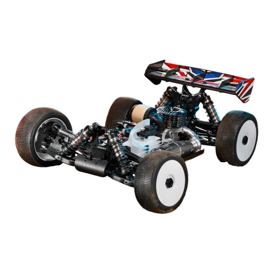
1/8 luxury nitro off-road buggy
Hide thumbs
Also See for XB8:
- Instruction manual (64 pages) ,
- Supplementary sheet (2 pages) ,
- Instruction manual (60 pages)
Table of Contents
Advertisement
Quick Links
Advertisement
Table of Contents

Related Manuals for Xray XB8


Summary of Contents for Xray XB8
-
Page 2: Safety Precautions
Fax: (214) 744-2401 excellent care of our customers. Email: info@teamxray.com Email: xray@rcamerica.com You can join thousands of XRAY fans and enthusiasts in our online community at: www.teamxray.com FAILURE TO FOLLOW THESE INSTRUCTIONS WILL BE CONSIDERED AS ABUSE AND/OR NEGLECT. SAFETY PRECAUTIONS WARNING: This product contains a chemical known to the state of California to XRAY parts for maximum performance. - Page 3 Part or parts missing from this kit must be reported within 30 days of purchase. No to XRAY or its distributors for warranty. XRAY reserves the right to make the final part or parts will be sent under warranty without proof of purchase. Should you determination of the warranty status of any component or part.
-
Page 4: Symbols Used
(HUDY #106471 7000cSt 100ml) To ensure that you always have access to the most up-to-date version of the XRAY Set-up Book, XRAY will now be offering only the digital online version at our website at www.teamxray.com. By offering this online version instead of including a hardcopy printed version in kits, you will always be assured of having the most current updated version. - Page 5 XB8 TECH TIPS FRONT & REAR DIFF GEAR MESH ADJUSTMENT If there is too much or too little diff side play, this may create non-optimal gear mesh between the diff gear and the pinion drive gear. This is easily resolved by inserting 1 or 2 of the included thin shims behind a diff outdrive ball-bearing, depending on how much play there is.
- Page 6 1. FRONT & REAR DIFFERENTIALS 355065 #355003 REAR XB8 FRONT/REAR DIFFERENTIAL 46T - V1 - SET 940816 964030 355064 FRONT 355022 971061 355091 355031 980261 355084 971061 903312 355031 #355022-G 964060 DIFFERENTIAL CASE - V2 - GRAPHITE 940816 355065 REAR...
- Page 7 1. FRONT & REAR DIFFERENTIALS Graphite Grease REAR (HUDY #106210) IMPORTANT! ➌ Use the same diff outdrives on both ends of a diff. FRONT 940816 ➋ BB 8x16x5 Graphite Grease STEP DETAIL ➎ Graphite Grease (HUDY #106210) DETAIL (HUDY #106210) 964060 Use HUDY Ball-Bearing Grease ➍...
-
Page 8: Center Differential
1. CENTER DIFFERENTIAL 355072 CENTER DIFF SPUR GEAR - LARGE 964030 #355056 INCLUDED 355031 #355057 OPTION #355058 OPTION 940816 964060 355082 355023 971061 355092 355031 964060 #355012 CENTER DIFFERENTIAL - V1 - SET 355031 355031 971061 964030 940816 355056 #355083 CENTER DIFF. - Page 9 1. CENTER DIFFERENTIAL ➌ ➋ Graphite Grease 940816 (HUDY #106210) BB 8x16x5 ➊ STEP DETAIL ➎ Use HUDY Ball-Bearing Grease DETAIL #106220 - STANDARD ➍ #106221 - BLUE 964060 #106222 - RED Graphite Grease S 6x18x0.2 (HUDY #106210) ➏ 971061 O 6x1.55 ➎...
-
Page 10: Front Transmission
908312 352006 XB8’16 DIFF BULKHEAD BLOCK SET FRONT/REAR 355472 DRIVE SHAFT BOOT (2) 355004 XB8 FRONT DIFFERENTIAL 46T - V2 - SET 355114 BEVEL DRIVE GEAR 14T 901404 HEX SCREW SB M4x4 (10) 355236 CVD DRIVE SHAFT COUPLING - HUDY SPRING STEEL™... -
Page 11: Rear Transmission
XB8’16 DIFF BULKHEAD BLOCK SET FRONT/REAR 355472 DRIVE SHAFT BOOT (2) 355005 XB8 REAR DIFFERENTIAL 46T - V2 - SET 353053 XB8 ALU REAR SHOCK TOWER - CNC MACHINED 7075 T6 (4MM) 901404 HEX SCREW SB M4x4 (10) 355114 BEVEL DRIVE GEAR 14T 908312... -
Page 12: Rear Suspension
#353113 XB8’16 COMPOSITE REAR LOWER SUSPENSION ARM - RIGHT #353123 XB8’16 COMPOSITE REAR LOWER SUSPENSION ARM - LEFT #353317 XB8 ALU REAR LOWER SUSP. HOLDER - FRONT - SQUARE ADJ. ROLL CENTER #353325 XB8 ALU REAR LOWER SUSP. HOLDER - REAR - SQUARE ADJ. ROLL CENTER... - Page 13 TRACK WIDTH The XRAY rear alu lower suspension holders provide even greater range of adjustment for the rear suspension. Using different combinations of eccentric bushings, fine adjustment of rear anti-squat, rear toe-in, rear roll center, and rear track-width can be obtained. For more information about the influence of rear anti-squat, rear toe-in, rear roll center and rear track width on car handling, please refer to HUDY Off-Road Set-up Book (#209099).
- Page 14 3. REAR SUSPENSION Install the pivot balls with Professional Multi Tool (HUDY #183011) DETAIL 1.5mm 901312 SB M3x12 901303 SB M3x3 STEP DETAIL ➍ 2.5~3.0mm 901305 SB M3x5 DETAIL 3x3mm 902318 ➌ SH M3x18 3x18mm 903308 ➋ SFH M3x8 ➊ SET-UP 3x5mm BOOK...
- Page 15 HEX SCREW SOCKET HEAD CAP SCH M3x18 (10) 353370 SET OF COMPOSITE REAR HUB CARRIER SHIMS 940814 HIGH-SPEED BALL-BEARING 8x14x4 BLUE COVERED (2) 353524 XB8'18 COMPOSITE REAR WING HOLDER 941318 HIGH-SPEED BALL-BEARING 13x19x4 BLUE COVERED (2) 355211 CVD DRIVE AXLE - HUDY SPRING STEEL™ 960030...
- Page 16 4. REAR SUSPENSION Ensure that the rear upright moves freely. If it does not move freely, use sandpaper to thin both wheelbase adjustment shims. 353370 SHIM 3x9x1 DETAIL Shims for wheelbase 353370 adjustment SHIM 3x9x2 1+1mm INITIAL SETTING 960030 N M3 DETAIL Do not overtighten the self-locking nut.
- Page 17 4. REAR SUSPENSION 903312 SFH M3x12 902314 SH M3x14 908318 SCH M3x18 960030 N M3...
-
Page 18: Front Suspension
OPTION 333450 ANTI-ROLL BAR BALL JOINT 5.8 MM (2) 357212 LOWER INNER PIVOT PIN F+R (2) 352006 XB8’16 DIFF BULKHEAD BLOCK SET FRONT/REAR 352120 XB8 COMPOSITE FRONT LOWER SUSPENSION ARM 901303 HEX SCREW SB M3x3 (10) 352323 ALU FRONT LOWER SUSP. HOLDER - FRONT - SQUARE ADJ. ROLL CENTER - V2... - Page 19 =308 =306 Outer position = 1mm or 1° from center =310* The XRAY alu front lower suspension holders provide even greater range of SET-UP adjustment for the front suspension. Using different combinations of eccentric BOOK The tables below describe the amounts of kick-up, front track-width change depending on the combinations bushings, fine adjustment of front kick-up, roll center, and front track-width of eccentric bushings used with 0 and 1mm, 1°...
- Page 20 5. FRONT SUSPENSION 1.5mm 901312 SB M3x12 Install the pivot balls with Professional Multi Tool (HUDY #183011) STEP DETAIL ➍ -2~0mm 901303 SB M3x3 901305 SB M3x5 DETAIL 3x3mm ➍ 902318 ➋ SH M3x18 3x18mm ➌ 903308 SFH M3x8 ➊ 3x5mm 3x8mm DETAIL...
- Page 21 352243 XB8’16 STEERING BLOCK - TRAILING AXLE - LEFT 901504 HEX SCREW SB M5x4 (10) 352372 XB8’17 ALU STEERING PLATE - SWISS 7075 T6 (L+R) 903312 HEX SCREW SFH M3x12 (10) 355222 UNIVERSAL DRIVE SHAFT - HUDY SPRING STEEL™ 940814...
- Page 22 6. FRONT SUSPENSION ALU pivot ball BLACK color DETAIL STEEL pivot ball SILVER color PIVOT BALLS MUST MOVE FREELY #357253 Brass Adjusting Nut M15x1 During initial assembly, tighten each hex nut until the pivot ball starts to bind, then loosen slightly. Verify that Tighten hex nuts using HUDY the pivot balls move freely.
-
Page 23: Front & Rear Assembly
903412 353280 353280 903412 902312 902335 HEX SCREW SH M3x35 (10) 351112 XB8’18 ALU CHASSIS - SWISS 7075 T6 (3MM) 902340 HEX SCREW SH M3x40 (10) 351200 FRONT & REAR BUMPER - V2 903412 HEX SCREW SFH M4x12 (10) 353082 XB8’18 COMPOSITE REAR BRACE - MEDIUM - M... - Page 24 6. FRONT & REAR ASSEMBLY Push the top of the holder with fingers together to insert the brace with body post. 902335 SH M3x35 960030 N M3 #353280 GRAPHITE BRACE SET for extra stiffness adjustment. 902340 SH M3x40 903412 SFH M4x12 960030 960040 N M3...
- Page 25 352084 XB8’16 COMPOSITE FRONT BRACE 902310 HEX SCREW SH M3x10 (10) 352050 XB8 ALU FRONT SHOCK TOWER - CNC MACHINED 7075 T6 (4MM) 902312 HEX SCREW SH M3x12 (10) 352314 COMPOSITE SQUARE ADJ. ROLL CENTER BUSHINGS - V2 (2) 903308...
- Page 26 7. STEERING 970121 DETAIL O 12.1x1.6 INITIAL PRELOAD SETTING DETAIL SET-UP BOOK SERVO SAVER HUDY Tool Allen 3.0mm 902308 SH M3x8 NOTE ORIENTATION DETAIL For servicing use Bearing Oil (HUDY #106230) 903410 SFH M4x10 940610 BB 6x10x3...
- Page 27 7. STEERING 902310 SH M3x10 All possible mounting alternatives of eccentric bushings 903308 SFH M3x8 DETAIL NOTE ORIENTATION SET-UP INITIAL SETTING BOOK ROLL CENTER 3x12mm 3x12mm 3x10mm DO NOT OVERTIGHTEN SCREWS DETAIL 3x12mm 902312 SH M3x12 903310 SFH M3x10 Check for free movement NOTE ORIENTATION...
- Page 28 7. STEERING 908312 SCH M3x12 NOTE ORIENTATION 1.0mm 1.0mm 2.0mm INITIAL SETTING #352051 XB8 GRAPHITE FRONT SHOCK TOWER 4MM All possible mounting alternatives of eccentric bushings UPPER CLIP Behind arm CASTER LOWER SHIM (Behind arm) UPPER CLIP (Behind arm) 24º...
- Page 29 8. CENTER DIFF & BRAKE #354051 #354112 GRAPHITE CENTER DIFF MOUNTING PLATE LIGHTWEIGHT VENTILATED BRAKE DISK - LASER CUT - PRECISION-GROUND (2) 902330 #354111 GRAPHITE VENTILATED BRAKE DISK - CNC MACHINED (2) 354073 901304 903308 354058 354041 354073 354130 902316 354041 354121 354010...
- Page 30 8. CENTER DIFF & BRAKE STEEL FIBRE FIBRE STEEL OVAL HOLE NOTE ORIENTATION ROUND HOLE Roughen steel plates with sandpaper before gluing fibre pads #354131 GLUED BRAKE PADS SET-ULTRA EFFICIENT (4) ROUND HOLE NOTE ORIENTATION OVAL HOLE NOTE ORIENTATION 902316 SH M3x16 For improved brake efficiency and increased lifespan use the Fibre pads together...
- Page 31 8. CENTER DIFF & BRAKE NOTE ORIENTATION 903308 SFH M3x8 NOTE ORIENTATION OF ALL PARTS 3x8mm 903412 SFH M4x12 4x12mm Before inserting 3x30 long screws, NOTE ORIENTATION loosen the four flat-head screws in OF ALL PARTS the upper plate by 1/2 turn (CCW). All screws Tighten all screws after assembly.
- Page 32 9. FUEL TANK & ENGINE #353250 XB8 GRAPHITE BRACE FOR CHASSIS SIDE GUARDS - SET 902316 908312 358941 906206 Manifold (NOT INCLUDED) Exhaust Pipe (NOT INCLUDED) 358605 964073 / 964074 / 964075 Screw Engine 358532 (NOT INCLUDED) (NOT INCLUDED) 358588...
- Page 33 Use appropriate shims to achieve proper S 7x10x0.2 clutchbell endplay Use the cone included with your engine, or use OPTION XRAY cone #358540 964074 S 7x10x0.3 When installing the engine, first check that the drive shaft does not touch the engine. If it does, remove some material from the engine mount as shown to make some room between engine and shaft.
- Page 34 GEAR MESH EXTREMELY IMPORTANT Adjust engine position to It is very important that your XB8 has properly-adjusted gear mesh. achieve proper gear mesh Adjust the gear mesh so there is adequate (or slightly larger) space between the spur gear and clutchbell teeth. Adjust the gear mesh by sliding the engine mounts in the slots of the chassis.
- Page 35 9. FUEL TANK & ENGINE 3x16mm DETAIL 902316 SH M3x16 2.2x6mm 903310 SFH M3x10 906206 SFP 2.2x6 3x10mm 901405 After running your engine, apply SB M4x5 (#106250 HUDY ENGINE AFTER RUN OIL) 903410 SFH M4x10 Cut away for muffler outlet DETAIL Mufler screw NOT INCLUDED...
- Page 36 10. RADIO CASE Servo Screw (NOT INCLUDED) 902306 356200 (NOT INCLUDED) Personal transponder 902312 (NOT INCLUDED) 902314 902310 356004 352460 352460 352670 306310 902310 302611 960030 902312 356004 902314 356004 Receiver Servo Grommet (NOT INCLUDED) (NOT INCLUDED) 356004 Steering Servo (NOT INCLUDED) Receiver battery 902314...
- Page 37 10. RADIO CASE step Servo screw (NOT INCULDED) Plug the connectors into the receiver in Step 2 902314 SH M3x14 NOTE NOTE ORIENTATION Use the shims only if the servo is too high and extends from the case step 3x10mm Use foam to cushion the inside of the radio case so the receiver and battery...
- Page 38 358162 FRONT SHOCK SHAFT (2) 358020 COMPOSITE SHOCK PARTS 11.1 358225 XB8’16 ALU REAR SHOCK BODY - HARD COATED (2) 358032 SHOCK PISTON SET 8-HOLE (1.2; 1.3) 10-H. (1.1MM) - DELRIN - V2 358263 XB8 REAR SHOCK SHAFT (2) 358033 COMPOSITE SHOCK 6-HOLE PISTON SET (1.2;...
- Page 39 1 1. SHOCK ABSORBERS DETAIL 358040 6 holes 6 holes Install the piston with Professional Multi S 2.5x6x0.5 ø1.3mm pistons ø1.3mm pistons Tool (HUDY #183011) 960026 SHORT rod LONG rod N M2.5 NOTE ORIENTATION 11.1 FRONT REAR SHOCK SHOCK DO NOT OVERTIGHTEN TIGHTEN GENTLY DETAIL The self-locking nut is overtightened, causing...
- Page 40 1 1. SHOCK ABSORBERS FRONT SHOCKS REAR SHOCKS DETAIL 970180 O 18x1.8 FRONT SHOCKS DETAIL REAR SHOCKS Professional Multi Tool (HUDY #183011) 1 mm DETAIL DEFAULT SHOCK REBOUND SETTING 0% (LOW REBOUND) Follow the steps below to set the shock rebound to the default setting of 0%. FRONT (SHORT) SET-UP HALF TIGHTEN...
- Page 41 1 1. SHOCK ABSORBERS FRONT shock PRELOAD DETAIL REAR SHOCKS FRONT SHOCKS SHORT front shock LONG rear shock REAR shock PRELOAD SHORT spring LONG spring IMPORTANT! SET-UP IMPORTANT! IMPORTANT! BOOK Both front shocks Both rear shocks SPRING RATE must be the same must be the same SHOCK PRELOAD FRONT &...
-
Page 42: Final Assembly
STEEL SCREW SHOCK PIVOT BALL WITH HEX (2) 902310 HEX SCREW SH M3x10 (10) 358105 XB8 FRONT SHOCK ABSORBERS + BOOTS COMPLETE SET (2) 902318 HEX SCREW SH M3x18 (10) 358206 XB8’16 REAR SHOCK ABSORBERS + BOOTS COMPLETE SET (2) - Page 43 12. FINAL ASSEMBLY SHORTER LONGER FRONT SHOCKS (SHORT) DETAIL INITIAL SETTING NOTE ORIENTATION 902318 902319 SH M3x18 SH M3x18 LEFT thread STANDARD 960030 M3x18 screw N M3 DETAIL 3x18mm INITIAL SETTING SET-UP On the front right arm use the SILVER M3x18 BOOK screw - this screw has...
- Page 44 To tighten the setscrew you can also use the HUDY 17mm Wheel Nut Tool #107570 WING SHIMS #353565 COMPOSITE INCLUDED WHEEL NUTS #293561 OPTION #355261 OPEN INCLUDED XRAY STARBURST WHEELS #293561-O ALU OPTION #293560 COVERED OPTION #359808 Pink OPTION #353561 OPTION #355265 COVERED OPTION #359809 Yellow OPTION...
- Page 45 12. FINAL ASSEMBLY #358832 AIR FILTER RAIN COVER 902308 SH M3x8 Apply #106240 HUDY air filter oil and follow the engine instructions to service the air filter. Cut the silicone tube depending on engine and muffler. Use the plastic clips to hold the tubes together. SILICONE TUBE MARKED AS BLUE = FROM FUEL TANK TO CARBURETOR SILICONE TUBE MARKED AS...
-
Page 46: Maintenance
MAINTENANCE ENGINE OPERATION PREPARING TO OPERATE THE ENGINE • Never modify the engine or muffler. • For proper engine break-in, please refer to the manual that came with the engine. • Confirm the position of needle and idling before running. Be sure to run a new engine smoothly. •... -
Page 47: Throttle Linkage Adjustment
THROTTLE LINKAGE ADJUSTMENT NEUTRAL (IDLE) ADJUST INDIVIDUAL LINKAGES SEPARATELY TO AVOID INTERFERING WITH THE OPERATION OF THE OTHERS 0.5mm ~1mm ENGINE IDLING IDLING ADJUSTMENT SCREW. Use to adjust the idle setting of the • Turn on the transmitter and receiver and set the engine control servo trim to the neutral position. carburetor. - Page 48 RC AMERICA, 2030 Century Center Blvd #15, Irving, TX 75062, USA PHONE: 214-744-2400, FAX: 214-744-2401, xray@rcamerica.com /TeamXray /TeamXray /TeamXray /TeamXrayRC /XrayRacing /XrayRacing...
Need help?
Do you have a question about the XB8 and is the answer not in the manual?
Questions and answers