Xray XB8 Instruction Manual
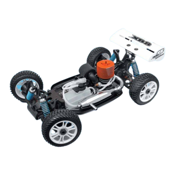
Xray xb8 1/8 luxury nitro off-road buddy
Hide thumbs
Also See for XB8:
- Instruction manual (64 pages) ,
- Supplementary sheet (2 pages) ,
- Instruction manual (45 pages)
Table of Contents

Related Manuals for Xray XB8


Summary of Contents for Xray XB8
-
Page 2: Table Of Contents
Therefore we ask you, if at all possible, to purchase ensure the free movement of all parts. XRAY products at your hobby dealer and give them your support like we do. • Clean all ball-bearings so they move very easily and freely. -
Page 3: Warnings
Take adequate safety precautions prior to operating this model. You are responsible for this model’s assembly and safe operation. Disregard of the any of the above cautions may lead to accidents, personal injury, or property damage. XRAY MODEL RACING CARS assumes no responsibility for any injury, damage, or misuse of this product during assembly or operation, nor any addictions that may arise from the use of this product. -
Page 4: Tools Included
SYMBOLS USED Part bags used Assemble in the Assemble left Assemble front Pay attention Assemble as Apply instant Apply oil Ensure smooth Use pliers specified order and right sides and rear the here many times glue non-binding the same way same way as specified movement... -
Page 5: Troubleshooting Guide
TROUBLESHOOTING GUIDE PROBLEM CAUSE SOLUTION Engine does not • Fuel tank is empty or carburetor is not • Fill fuel tank with fuel and prime start primed • Replace glowplug or recharge/replace glowdriver • Bad glowplug or dead glowdriver battery battery •... -
Page 6: Front & Rear Differential
1. FRONT & REAR DIFFERENTIAL 355060 940816 355020 971060 971030 964060 front differential only 355090 980212 355030 355080 355030 964030 355040 903312 BAGS 35 5020 DIFFERENTIAL CASE 94 0816 HIGH-SPEED BALL-BEARING 8x16x5 BLUE COVERED (2) 35 5030 STEEL DIFF BEVEL & SATELLITE GEARS (2+4) 96 4030 WASHER S 3.5x12x0.2 (10) 35 5040... -
Page 7: Front & Rear Differential
FRONT & REAR DIFFERENTIAL 940816 BB 8x16x5 Use tweezers to insert pin 964060 S 6x18x0.2 971060 O 6x1.5 980210 P 2x11.6 FRONT DIFFERENTIAL REAR DIFFERENTIAL 903312 SFH M3x12 971030 O 3x1.5 964030 S 3.5x12x0.2 Use O-rings in FRONT diff Push shim against O-ring so it only sits in groove Front diff:... -
Page 8: Center Differential
CENTER DIFFERENTIAL 355070 940816 355020 971060 971030 355090 964060 980212 355030 355080 355030 964030 355050 903312 35 5020 DIFFERENTIAL CASE 90 3312 HEX SCREW SFH M3x12 (10) 35 5030 STEEL DIFF BEVEL & SATELLITE GEARS (2+4) 94 0816 HIGH-SPEED BALL-BEARING 8x16x5 BLUE COVERED (2) 35 5050 CENTER DIFF SPUR GEAR 46T - HUDY STEEL 96 4030... - Page 9 CENTER DIFFERENTIAL 940816 BB 8x16x5 Use tweezers to insert pin 964060 S 6x18x0.2 971060 O 6x1.5 980212 P 2x11.6 903312 SFH M3x12 971030 O 3x1.5 964030 S 3.5x12x0.2 Push shim against O-ring so it sits in groove Tight the screws equally Finish tightening in this order Center diff: THICK silicone oil 5.000~10.000W...
-
Page 10: Front & Rear Transmission
2. FRONT TRANSMISSION 355400 901504 940816 352000 355110 355000 352000 902310 351300 352090 902310 35 1300 BODY POSTS 90 1504 HEX SCREW SB M5x4 (10) 35 2000 DIFF BULKHEAD BLOCK SET FRONT 90 2310 HEX SCREW SH M3x10 (10) 35 2090 ALU FRONT SHOCK TOWER - CNC MACHINED 7075 T6 (4MM) 94 0816 HIGH-SPEED BALL-BEARING 8x16x5 BLUE COVERED (2) -
Page 11: Rear Transmission
REAR TRANSMISSION 355600 901504 940816 352001 355110 355000 352001 902310 351300 353090 902310 35 1300 BODY POSTS 90 1504 HEX SCREW SB M5x4 (10) 35 2001 DIFF BULKHEAD BLOCK SET REAR 90 2310 HEX SCREW SH M3x10 (10) 35 3090 ALU REAR SHOCK TOWER - CNC MACHINED 7075 T6 (4MM) 94 0816 HIGH-SPEED BALL-BEARING 8x16x5 BLUE COVERED (2) -
Page 12: Rear Suspension
ALU REAR LOWER SUSP . HOLDER 2°-4°- REAR - 7075 T6 (5MM) 90 9395 SCREW PHILLIPS SS 3.5x45 (10) DOWNSTOP SETTING Tighten screws equally 901408 3.5x45 SB M4x8 3 mm XRAY 909369 2° - 4° Downstop screw FRONT VIEW SS 3.5x19 REAR VIEW 3.5x19 909395 SS 3.5x45... - Page 13 4. REAR SUSPENSION 353520 353550 353360 902310 902320 960030 902316 353160 353130 960030 352630 353150 353170 902316 353350 902322 357330 980317 355200 902305 940816 960030 353350 355250 901504 35 2630 ADJ. TURNBUCKLE M5 L/R 50 MM - SPRING STEEL (2) 35 7330 REAR LOWER OUTER PIVOT PIN (2) 35 3130...
-
Page 14: Rear Suspension
REAR SUSPENSION 902305 SH M3x5 Shims for wheel base adjustment Note location of notch Note location of notch 902316 SH M3x16 3x16 3x16 3x22 3x22 INITIAL POSITIONS 902322 Left thread Right thread SH M3x22 16 mm 960030 N M3 902310 SH M3x10 3x16 3x10... -
Page 15: Front Suspension
5. FRONT SUSPENSION 909369 352320 352315 902318 901408 352110 352315 352110 357210 352310 909395 901303 352424 352470 352450 352000 901312 901305 903308 352460 35 2000 DIFF BULKHEAD BLOCK SET FRONT 35 7210 LOWER INNER PIVOT PIN F/R (2) 35 2110 FRONT LOWER ARM 90 1303 HEX SCREW SB M3x3 (10) -
Page 16: Front Suspension
6. FRONT SUSPENSION 903312 352330 352130 352260 357220 352220 352380 352315 352620 352150 902412 353170 352180 902322 960030 902305 357230 352210 352295 352170 352171 352172 902416 355200 980317 940816 352250 352295 901504 355250 35 2130 FRONT UPPER ARM 35 3170 PIVOT BALL 6.8 (4) 35 2150 FRONT UPPER ARM BALL JOINT (2) -
Page 17: Front Suspension
FRONT SUSPENSION 902305 SH M3x5 DISASSEMBLY ASSEMBLY Remove 3x5 screw holding eccentric bushing in arm. Push out the pivot pin from the rear to remove the Press pivot ball into arm until it snaps into place eccentric bushing. DOT IN FRONT Notch goes to outside DOT IN FRONT 8.5 mm... -
Page 18: Front & Rear Assembly
FRONT & REAR ASSEMBLY 902308 353085 351200 351200 903412 903308 903412 351100 35 1200 FRONT & REAR BUMPER 90 3412 HEX SCREW SFH M4x12 (10) 35 3085 ALU REAR BRACE 7075 T6 (5MM) 90 2308 HEX SCREW SH M3x8 (10) 35 1100 ALU CHASSIS - CNC MACHINED 7075 T6 (3MM) 90 3308... - Page 19 FRONT & REAR ASSEMBLY 902308 SH M3x8 SH M3x8 903308 SFH M3x8 SFH M3x8 903412 SFH M4x12...
-
Page 20: Steering
7. STEERING 903310 903308 903306 351340 940610 903310 352500 960030 352080 352570 352080 352510 352610 352660 352080 352650 352500 352510 960030 903308 971120 352500 940610 903410 35 1340 GRAPHITE UPPER PLATE 90 3306 HEX SCREW SFH M3x6 (10) 35 2080 FRONT TORQUE ROD SET 90 3308 HEX SCREW SFH M3x8 (10) -
Page 21: Steering
STEERING 903310 SFH M3x10 940610 BB 6x10x3 3x10 3x10 FASTEN 903306 SFH M3x6 TIGHTLY SHORT 903308 SFH M3x8 LONG 903310 SFH M3x10 903410 SFH M4x10 4x10 4x10 960030 N M3 24.5 mm Tighten all steering fasteners securely... -
Page 22: Center Diff & Brake
8. CENTER DIFF & BRAKE 902330 358930 354040 903308 354050 902308 901304 354040 354050 354040 354120 354130 354010 902316 355010 354110 354010 903412 903308 35 4010 CENTER DIFF MOUNTING PLATE - SET 90 1304 HEX SCREW SB M3x4 (10) 35 4040 BRAKE CAM POST &... -
Page 23: Center Diff & Brake
CENTER DIFF & BRAKE 901304 SB M3x4 2 mm 902308 0 mm SH M3x8 903308 SFH M3x8 Before inserting 3x30 long screws, loosen the four flat-head screw in the upper graphite plate by 1/2 turn. Tighten all screws after assembly. 902330 SH M3x30 NOTE ORIENTATION... -
Page 24: Fuel Tank & Engine
9. FUEL TANK & ENGINE Manifold not included 908312 Pipe not included Engine not included 964070 964071 Screw not included 964072 358531 358540 358550 961025 358710 358580 358581 358560 940510 960030 902316 358513 358720 358600 962050 960030 902308 902308 351150 358680 358720 901405... -
Page 25: Fuel Tank & Engine
FUEL TANK & ENGINE Tight the flywheel nut with cross-wrench 3x12 902308 SH M3x8 908312 SCH M3x12 940510 BB 5x10x4 7x12x0.2/0.3/0.5 962050 961025 S 5x10x1 S 2.5 5x10 Use appropriate shims to achieve 964070 964071 S 7x12x0.2 S 7x12x0.3 proper clutchbell endplay Note the orientation of the clutch shoes. -
Page 26: Radio Case
BRAKE/THROTTLE ARMS & STEERING SERVO ARMS - SET 96 0030 NUT M3 (10) 35 6600 TRANSPONDER MOUNT 38 9111 XRAY BATTERY 5-CELL -1200mAh NiMH- 6.0V PRO 30 6310 ANTENNA TUBE (2) Ball joints must be 90° to each other cca 16 mm 902312... -
Page 27: Radio Case
RADIO CASE KO PROPO 3x10 Route steering servo lead 902308 behind lead clamp SH M3x8 FUTABA 902310 NOTE ORIENTATION SH M3x10 SANWA 3x10 NOTE ORIENTATION 903308 Use appropriate servo stands SFH M3x8 Servo screw Servo stands Route receiver wire through mounting hole in top plate and through antenna tube 903308... -
Page 28: Shock Absorbers
96 1025 WASHER S 2.5 (10) 35 8080 SHOCK RUBBER MEMBRANE (4) 96 8070 G-CLIP 7 (10) 35 8095 XRAY SPRING-SET SOFT LIGHT-BLUE (2+2) 97 1035 SILICONE O-RING 3.5x2 (10) 35 8096 XRAY SPRING-SET HARD DARK-BLUE (2+2) FRONT SHOCKS 11.1... -
Page 29: Shock Absorbers
SHOCK ABSORBERS 1. Install the pivot ball into the composite pivot mount. 2. Extend the shock rod so the piston is near the bottom of the shock body. Shock Silicone Oil 350W 3. Hold shock upright and slightly overfill the shock body with shock oil. 4. -
Page 30: Final Assembly
12. FINAL ASSEMBLY 358950 901303 961022 903314 356400 903312 356510 from servo 902310 353510 356400 356400 356200 960030 353510 356400 358045 356400 356400 356400 960030 356400 358900 358200 902322 902318 358930 358810 359800 358820 902322 not included 358840 358820 not included 902308 960030 358840... -
Page 31: Final Assembly
FINAL ASSEMBLY REAR SUSPENSION 3x22 902318 SH M3x18 902322 SH M3x22 REAR SHOCKS (LONG) INITIAL POSITIONS 960030 N M3 3x18 SILICONE TUBING 901303 SB M3x3 10mm 2xCUT Use servo horn depending on your servo 902310 SH M3x10 K - KO Propo Thread brake rods into plastic F - Futaba pivots until flush with outer end... - Page 32 FINAL ASSEMBLY Cut the silicone tube depending on engine and muf- fler. Use the plastic clips to hold the tubes together The fuel filter has a small hole that fits into notch on the composite holder to prevent the filter from turning freely Use the fuel tubing holders where neccessary...
-
Page 33: Throttle Linkage Adjusment
THROTTLE LINKAGE ADJUSTMEN Neutral (Idle) ADJUST INDIVIDUAL LINKAGES SEPARATELY TO AVOID INTERFERING WITH THE OPERATION OF THE OTHERS 0.5mm Engine idling cca 1mm Idling Adjustment Screw. * Turn on the transmitter and receiver and set the engine control servo trim to the neutral position. Use to adjust the idle setting of the carburetor. -
Page 34: Body Preparation
BODY PREPARATION HOLE FOR BODY POSTS ø 9mm • Apply paint masks as appropriate. • Before cutting and making holes on the body, put the unpainted body on the chassis to confirm the mounting position and location for holes and cutouts. •... -
Page 35: Engine Operation
ENGINE OPERATION Preparing to operate the engine • Never modify the engine or muffler. • Confirm the position of needle and idling before running. Be sure to run a new engine smoothly. • Make sure the air filter is clean and oiled. •... -
Page 36: Set-Up
Everything necessary to achieve a full range of adjustment is included in your XB8 kit. Please refer to the XB8 Basic Set-Up Sheet for a good overall starting point. After rebuilding the chassis, or in case you become lost with your set-up, always return to the basic starting set-up described here. - Page 37 Adjust the shock absorbers and their mounting positions to suit track conditions. Shock Oil Piston Hole Type You can use shock oils of different weights in a shock absorber. There are two different types of shock pistons that can be used in the XB8. Shock Oil Characteristics Piston hole type...
- Page 38 XB8 SET-UP Shock Springs You can use shock springs of different rates to alter performance. Shock spring Characteristics Softer · more chassis roll · more traction · better on bumpy tracks · increases chance of bottoming out when landing Stiffer ·...
- Page 39 XB8 SET-UP Servo Saver Preload Adjust the preload of the central servo saver by adjusting the tension on the spring with the threaded collar. Servo saver spring preload Characteristics Softer · less steering · better suited to standard servos Stiffer ·...
- Page 40 XB8 SET-UP H FRONT KICK-UP Adjust front kick-up of the front lower arms by changing the eccentric bushings in the plate at the rear of the front bulkhead. You should also adjust the angle of the front upper arms so that they are parallel with the front lower arms.
- Page 41 XB8 SET-UP H TOE You can adjust different types of toe angle on the XB8: front inboard toe, front toe, and rear toe-in. IMPORTANT! Make equal adjustments on both left and right sides of the car. Front Inboard Toe Adjust front inboard toe of the front lower arms by changing the eccentric bushings in the plate at the very front of the front bulkhead.
- Page 42 XB8 SET-UP H REAR ANTI-SQUAT Adjust rear anti-squat of the rear lower arms by changing the eccentric bushings in the plate at the front of the rear bulkhead. IMPORTANT! Make equal adjustments on both left and right sides of the car.
- Page 43 Use only the genuine premium quality Changing the oil in the front differential affects overall steering response. Xray silicone diff oils. The differential Changing the oil in the center differential affects the front-to-rear drive. oils are availabe in 50ml size in these Changing the oil in the rear differential affects cornering traction and overall steering.
- Page 44 XRAY MODEL RACING CARS XRAY MODEL RACING CARS XRAY MODEL RACING CARS P .O.BOX 103 P .O.BOX 103 P .O.BOX 103 911 50 TREN 911 50 TRENČÍ ČÍN 911 50 TRENČÍN SLOVAKIA, EUROPE SLOVAKIA, EUROPE SLOVAKIA, EUROPE PHONE: ++421 905 402724...
Need help?
Do you have a question about the XB8 and is the answer not in the manual?
Questions and answers