Xray XB4 Instruction Manual
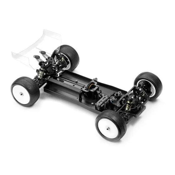
High-competition premium luxury racing 1/10
electric 4wd off-road buggy
Hide thumbs
Also See for XB4:
- Instruction manual (52 pages) ,
- Instruction manual (56 pages) ,
- Instruction manual (40 pages)

Related Manuals for Xray XB4


Summary of Contents for Xray XB4
-
Page 2: Safety Precautions
Phone: (800) 519-7221 * (214) 744-2400 many other goodies. We pride ourselves on taking excellent care of our customers. Fax: +421-32-7401109 Fax: (214) 744-2401 You can join thousands of XRAY fans and enthusiasts in our online community at: Email: info@teamxray.com Email: xray@rcamerica.com www.teamxray.com Failure to follow these instructions will be considered as abuse and/or neglect. - Page 3 Therefore we ask you, if at all possible, to purchase • For the best performance, it is very important that great care is taken to ensure XRAY products at your hobby dealer and give them your support like we do. If the free movement of all parts.
- Page 4 Allen 2.0mm EQUIPMENT INCLUDED INCLUDED To ensure that you always have access to XRAY offers wide range of optional XRAY Premium Silicone Oils Graphite Grease SAMPLE OF the most up-to-date version of the Set-up tuning parts which are listed in a...
- Page 5 MOTOR POSITION ALTERNATIVES The XB4 can be assembled to fit either the saddle battery pack or short battery pack. Depending on the version you choose to build you have to follow the assembly instructions. The Instruction Manual shows the assembly of saddle pack batteries. If you want to build the car with the alternative short battery pack (rearward motor position), follow the supplementary instructions starting on page 39 (using parts from Bag 09).
- Page 6 1. FRONT & REAR DIFFERENTIAL 941015 981210 BEVEL & SATELITTE GEARS + PINS #304930 + #304980 COMPOSITE (STANDARD) #335030 + #335080 STEEL (OPTION) 964031 972050 304930 364960 BEVEL GEARS #364935 GRAPHITE (OPTION) 304980 #364945 ALU (OPTION) 364910 #364955 STEEL (STANDARD) 964050 964050 304930...
- Page 7 FRONT & REAR DIFFERENTIAL Front diff Rear diff 8 000cSt 8 000cSt Silicone oil Silicone oil Fill just above the Fill just above the satellite gears. satellite gears. 964031 S 3.5x10x0.2 PROPER AMOUNT OF OIL IN THE DIFFS Use a digital scale to measure the exact amount of oil in the diff.
- Page 8 2. REAR CENTRAL TRANSMISSION MARKED “R“ IMPORTANT 363080 902310 REAR BLOCK 365423 980210 365470 362001 365230 365440 940510 365134 364900+364955 940815 902306 BEVEL DRIVE GEARS 362001 #365114 GRAPHITE (OPTION) 902310 #365134 STEEL (STANDARD) 36 2001 DIFF BULKHEAD BLOCK SET REAR - V2 90 2306 HEX SCREW SH M3x6 (10) 36 3080...
- Page 9 REAR CENTRAL TRANSMISSION DETAIL When installing the gear on the axle, make sure the 902306 flat spot of the gear sits on the flat spot of the axle. SH M3x6 NOTE ORIENTATION ➍ 940510 BB 5x10x4 ➊ NOTE ORIENTATION IMPORTANT REAR BLOCK THREAD LOCK 940815...
- Page 10 2. FRONT CENTRAL TRANSMISSION MARKED “F“ IMPORTANT 365422 FRONT BLOCK 980210 365440 940510 365230 365470 365134 364900+ 364955 362000 362000 940815 902306 902310 BEVEL DRIVE GEARS 362081 #365114 GRAPHITE (OPTION) 902310 #365134 STEEL (STANDARD) 36 2000 DIFF BULKHEAD BLOCK SET FRONT - V2 90 2310 HEX SCREW SH M3x10 (10) 36 2081...
- Page 11 FRONT CENTRAL TRANSMISSION DETAIL When installing the gear on the axle, make sure the 902306 flat spot of the gear sits on the flat spot of the axle. SH M3x6 NOTE ORIENTATION ➍ 940510 BB 5x10x4 ➊ NOTE ORIENTATION IMPORTANT GRAPHITE GREASE FRONT BLOCK (HUDY #106210)
- Page 12 3. REAR SUSPENSION 903312 363121 363321 362315 367210 306219 362315 363111 902308 363311 903312 901304 362001 ANTI-ROLL BARS #362470 1.0mm (OPTION) 901303 #362471 1.1mm (OPTION) #362472 1.2mm (STANDARD) 303431-K #362473 1.3mm (OPTION) #362474 1.4mm (OPTION) 303454 #362476 1.6mm (OPTION) #362478 1.8mm (OPTION) 901308 Remove the 3x6.5x2mm shim from each rear arm, this shim will be used in Rear Transmition section on page 19, step 1.
- Page 13 Outer position = 1° or 0.75mm from center. The XRAY rear alu lower suspension holders provide great range of adjustment for the rear suspension. Using different combinations of eccentric bushings, fine adjustment of rear anti-squat, rear toe-in, rear roll center, and rear track-width can be obtained. For more information about the influence of rear anti-squat, rear toe-in, rear roll center and rear track width on car handling, please refer to HUDY Set-up Book (#209100).
- Page 14 REAR SUSPENSION 901308 SB M3x8 ASSEMBLY VIEW 1.5mm STEP DETAIL ➌ 901303 SB M3x3 901304 SB M3x4 902308 SH M3x8 ➌ ➋ ➊ DETAIL DETAIL Step ➊ Loosen the 3x4 setscrew if the anti-roll bar does not Step check for free movement ➊...
- Page 15 3. FRONT SUSPENSION 903312 362315 362320 367210 306219 362315 362310 903312 361200 902308 362111 901303 ANTI-ROLL BARS 303454 #362470 1.0mm (OPTION) #362471 1.1mm (OPTION) #362472 1.2mm (STANDARD) 901308 #362473 1.3mm (OPTION) 303431-K 362000 #362474 1.4mm (OPTION) 901304 #362476 1.6mm (OPTION) 303454 902308 #362478 1.8mm (OPTION)
- Page 16 Outer position = 1° or 0.75mm from center. The XRAY alu front lower suspension holders provide great range of adjustment for the front suspension. Using different combinations of eccentric bushings, fine adjustment of front kick-up, roll-center, and front track-width can be obtained. For more information about the influence of kick-up, front track-width, and roll centers on car handling, please refer to HUDY Set-up Book (#209100).
- Page 17 FRONT SUSPENSION ASSEMBLY VIEW 1.5mm 901308 SB M3x8 902308 SH M3x8 STEP DETAIL ➌ 901303 SB M3x3 901304 SB M3x4 902308 ➌ SH M3x8 ➋ ➊ DETAIL DETAIL Step ➊ Loosen the 3x4 setscrew if the anti-roll bar does not Step check for free movement ➊...
- Page 18 4. REAR TRANSMISSION 363520 DRIVE SHAFT COLLAR #365470 COMPOSITE (STANDARD) #365471-K ALU - BLACK (OPTION) #365471-O ALU - ORANGE (OPTION) REAR UPRIGHTS 365320 980210 #363350 COMPOSITE (STANDARD) #363351 ALU (OPTION) 363350 365470 365230 365340 902205 902310 940510 302665 940512 363111 363121 365350 362651...
- Page 19 REAR TRANSMISSION IMPORTANT! When using OUTSIDE position on the hub, The outside hole offers great stability and is 901306 use only outside position on the arm. recommended for bumpy open tracks. Check for free SB M3x6 movement When using INSIDE position on the hub, Inside hole offers great amount of steering use only inside position on the arm.
- Page 20 4. FRONT TRANSMISSION 302665 C-HUBS DRIVE SHAFT COLLAR 362652 #362210 RIGHT 9° (STANDARD) #365470 COMPOSITE (STANDARD) 362280 362610 362651 #362211 RIGHT 6° (OPTION) #365471-K ALU - BLACK (OPTION) 303122 #362220 LEFT 9° (STANDARD) 960030 #365471-O ALU - ORANGE (OPTION) #362221 LEFT 6° (OPTION) 902314 362651...
- Page 21 FRONT TRANSMISSION Check for free movement 901306 SB M3x6 DO NOT OVERTIGHTEN ➋ 20mm (HUDY #107633) ARM REAMER If the C-hub does not move freely, use a HUDY Arm Reamer to NOTE resize the hole. ORIENTATION ➊ RIGHT THREAD 34 mm 10mm THREAD THREAD...
- Page 22 4. FRONT & REAR ASSEMBLY 902316 902312 361320 361182 903314 361291 361292 960030 961032 361263 361263 361102 902314 903310 903310 903310 903310 902314 903308 903310 90 3308 HEX SCREW SFH M3x8 (10) 36 1182 COMPOSITE REAR LOWER BRACE 90 3310 HEX SCREW SFH M3x10 (10) 36 1291 COMPOSITE CHASSIS BRACE FRONT...
- Page 23 FRONT & REAR ASSEMBLY 903308 SFH M3x8 903310 SFH M3x10 903314 SFH M3x14 960030 N M3 961032 3x14 S 3.2 3x10 CHASSIS FLEX SETTING 903310 SFH M3x10 Screws for Multi-Flex™ setting. For more details see page 45.
- Page 24 4. FRONT & REAR ASSEMBLY 3x16 OPTIONAL To raise the rear differential and rear suspension use these two optional parts together. #361262 902314 SH M3x14 Composite Rear Chassis Plate #361181 Graphite Rear Lower Brace 2.0mm 902316 SH M3x16 903310 SFH M3x10 3x12 902312 SH M3x12...
- Page 25 5. STEERING 902306 STEERING PLATE #362571 COMPOSITE (STANDARD) 362580 #362573 ALU (OPTION) 940508 362290 362510 940508 362571 302665 902310 362540 362610 362280 362290 302665 362510 362652 902310 362510 302665 362610 332561 302665 332540 940508 970100 362550 303125 903310 30 2665 COMPOSITE BALL JOINT 4.9MM - CLOSED WITH HOLE (4) 36 2580 STEERING BRACE 2.0MM GRAPHITE...
- Page 26 STEERING 902306 SH M3x6 902310 SH M3x10 3x10 3x10 940508 BB 5x8x2.5 903310 SFH M3x10 3x6x3 303125 SHIM 3x6x3 32mm LEFT THREAD RIGHT THREAD LEFT THREAD RIGHT THREAD 362280 NOTE ORIENTATION CON. SHIM 3x6x2 Adjustment block towards outside INITIAL POSITION CONICAL SHIM 3x6x2 Check for free...
- Page 27 6. SLIPPER CLUTCH ASSEMBLY 361320 OPTIONAL: OPTIONAL: 902310 #364021 ALU CENTRAL #364901 GEAR CENTER DIFFERENTIAL - SET BULKHEAD 361165 361164 902310 364111 361321 903308 361163 941015 364130 980212 361184 902308 981208 364130 364120 364022 365781 903308 903310 364190 902318 902305 364011 364120 SLIPPER CLUTCH SPUR GEARS...
- Page 28 SLIPPER CLUTCH ASSEMBLY NOTE ORIENTATION 903310 SFH M3x10 TIGHTEN GENTLY 903310 SFH M3x10 902318 SH M3x18 NOTE ORIENTATION BEARING OIL (HUDY #106230) 941015 BB 10x15x4...
- Page 29 SLIPPER CLUTCH ASSEMBLY SLIPPER CLUTCH ADJUSTMENT The Slipper Clutch can be adjusted by loosening the set-screw and then, while keeping the Untighten set-screw ➊ tool inside of the set-screw, rotating the spur gear by hand as indicated in the drawing. Adjust ➋...
- Page 30 7. SHOCK ABSORBERS PISTONS DETAIL 368010 holes holes holes holes holes holes (Create custom holes) 965023 (1.4mm) (1.3mm) (1.0mm) (1.1mm) (1.2mm) (0mm - use required drill pin) 368030 368160 363240 368120 Thick Shim Thick Shim Thin Shim 902205 970120 306219 970080 368260 972030...
- Page 31 SHOCK ABSORBERS Downstop shim. THICKER shim used, INITIAL SETTING GREATER downstop is achieved. EXTREMELY IMPORTANT 306219 IMPORTANT SHIM 3x6x1 Always use same shim thickness on right 2mm 3mm and left side to achieve same downstop. ➋ ➋ 3x6x1 ➊ 3x6x1 ➊...
- Page 32 SHOCK ABSORBERS FRONT SHOCKS (SHORT) REAR SHOCKS (LONG) IMPORTANT Both FRONT SHOCKS must be the same overall length. SHORT FRONT SHOCKS LONG REAR SHOCKS Both REAR SHOCKS must be the same overall length. Short Springs Long Springs ALTERNATE SHOCK REBOUND SETTING (50% AND 100%) The default shock rebound setting is 0% (as described on page 34).
-
Page 33: Final Assembly
COMPOSITE BATTERY STRAP L+R 36 3510 LEXAN REAR WING (2) 36 6142 COMPOSITE BATTERY HOLDER STAND (2) 36 9702 XRAY XB4 BODY - WIDE 36 6200 COMPOSITE SERVO MOUNT (2) 36 9910 FRONT WHEELS AERODISK - WHITE (2) 36 6202... - Page 34 FINAL ASSEMBLY ➋ INITIAL POSITION 960030 N M3 ➊ ➍ NOTE ORIENTATION 902316 SH M3x16 ➌ 3x16 ➋ INITIAL POSITION 960030 N M3 ➊ ➍ 902312 SH M3x12 NOTE ORIENTATION 3x12 ➌ SERVO LINK Adjust servo link to fit your servo. 6mm THREAD RIGHT 26mm...
- Page 35 FINAL ASSEMBLY NOTE ORIENTATION REMOVE FRONT & CENTER LONG UPPER-DECK 903310 SFH M3x10 SHORT VIEW OF RADIO PLATE SPEED CONTROLLER NOTE: In case the antenna tube does not hold the antenna properly, (NOT INCLUDED) apply a small drop of the CA glue to the outside end of the antenna tube while inserting it into the holder.
- Page 36 FINAL ASSEMBLY NOTE Adjust the motor so the pinion meshes with the spur gear ORIENTATION properly. Make sure the gear mesh is not too tight. There should be a small amount of play between the teeth of the pinion gear and the spur gear. ➋...
- Page 37 FINAL ASSEMBLY ASSEMBLY BACK FRONT & CENTER UPPER-DECK Before cutting and making holes on the BODY, put the unpainted body on the Apply paint masks as appropriate. ➊ ➍ chassis to confirm the mounting position and location for holes and cutouts. Before cutting and making holes on the WING, put the unpainted wing on the Paint the body using paints formulated for polycarbonate bodies.
- Page 38 FINAL ASSEMBLY 960240 N M4 REAR WIDE WHEEL FRONT NARROW WHEEL 903308 SFH M3x8 OPTIONAL WING SHIM #293561 ALU REAR WING SHIM SILVER (OPTION) #293561-O ALU REAR WING SHIM ORANGE (OPTION) FINAL ASSEMBLY VIEW...
- Page 39 MOTOR POSITION ALTERNATIVES The XB4 can be assembled to fit either the saddle battery pack or short battery pack. Depending on the version you choose, you will need to follow different assembly instructions. Saddle Pack Batteries (forward motor position): Follow the assembly steps on pages 6-38.
- Page 40 REARWARD MOTOR POSITION PAGE 8 / STEP 1 CENTRAL DRIVE SHAFT (95MM) - LONGER 980210 P 2x10 ➋ ➌ ➊ ➍ GRAPHITE GREASE (HUDY #106210) PAGE 9 / STEP 2 902310 NOTE ORIENTATION - DIFF GEAR ON OPPOSITE SIDE SH M3x10 REAR DIFF 8 000 cSt PAGE 10 / STEP 1...
- Page 41 REARWARD MOTOR POSITION PAGE 23 / STEP 1 903308 SFH M3x8 903310 SFH M3x10 960030 N M3 961032 S 3.2 3x10 3x10 3x10 Use the position based on the size of servo. 3x10 PAGE 26 / STEP 1 PAGE 26 / STEP 2 902310 NOTE ORIENTATION SH M3x10...
- Page 42 REARWARD MOTOR POSITION PAGE 28 / STEP 1 NOTE ORIENTATION - STAND IN DIFFERENT LOCATION 903310 SFH M3x10 PAGE 28 / STEP 2 TIGHTEN GENTLY 903310 SFH M3x10 NOTE ORIENTATION 902318 SH M3x18 PAGE 28 / STEP 3 NOTE ORIENTATION - SLIPPER CLUTCH DIRECTION IS REVERSED BEARING OIL (HUDY #106230) 941015 BB 10x15x4...
- Page 43 REARWARD MOTOR POSITION PAGE 29 / STEP 3 3x10 3x10 902308 SH M3x8 902310 SH M3x10 PAGE 34 / STEP 4 NOTE ORIENTATION LONG 902308 SH M3x8 SHORT FROM SERVO PAGE 35 / STEP 1 SHORT LONG NOTE ORIENTATION 903310 SFH M3x10...
- Page 44 REARWARD MOTOR POSITION PAGE 35 / STEP 3 Loosen the screw ➊ Insert motor into the bulkhead ➋ ➊ ➋ PAGE 35 / STEP 2 RECEIVER (NOT INCLUDED) SPEED CONTROLLER NOTE: In case the antenna tube does not hold the antenna properly, apply 903310 (NOT INCLUDED) a small drop of the CA glue to the outside end of the antenna tube while...
- Page 45 FINAL ASSEMBLY VIEW MULTI-FLEX™ You can adjust the chassis flex by adding or removing the screws in the center of the chassis. The less screws used the softer the chassis flex will be. The more screws used the stiffer the chassis flex will be. LESS SCREWS = SOFT FLEX SETTING MORE SCREWS = STIFFER FLEX SETTING IMPORTANT...
- Page 46 Ball-bearings in an off-road car must be properly maintained for smooth operation and long lifespan. The XB4 ball-bearings are degreased and are lubricated with HUDY Bearing Oil. The following procedures are recommended to clean all of the bearings in your off-road car. For high-competition racing, we recommended doing this every 3-4 weeks, or before a major race.
- Page 47 INSERTS WHEELS ELECTRONICS #107720 GAUGE MOTOR SPEEDO TIMING BATTERIES ELECTRONICS LAYOUT SERVO POSITION LEFT RIGHT MOTOR POSITION FRONT REAR SPEEDO POSITION LEFT RIGHT RECEIVER POSITION LEFT RIGHT BATTERY TYPE SADDLE PACK SHORT COMMENTS XB4’ SET-UP SHEET VER. 1.0 ©XRAY 2015...
- Page 48 RC AMERICA, 2030 Century Center Blvd #15, Irving, TX 75062, USA PHONE: 214-744-2400, FAX: 214-744-2401, xray@rcamerica.com...
Need help?
Do you have a question about the XB4 and is the answer not in the manual?
Questions and answers