Sign In
Upload
Download
Table of Contents
Contents
Add to my manuals
Delete from my manuals
Share
URL of this page:
HTML Link:
Bookmark this page
Add
Manual will be automatically added to "My Manuals"
Print this page
×
Bookmark added
×
Added to my manuals
Manuals
Brands
Gigabyte Manuals
Motherboard
R281-Z91
Service manual
Gigabyte R281-Z91 Service Manual
Mz91-fs0 chipset
Hide thumbs
1
2
3
4
5
6
Table Of Contents
7
8
9
10
11
12
13
14
15
16
17
18
19
20
21
22
23
24
25
26
27
28
29
30
31
32
33
34
35
36
37
38
39
40
41
42
43
44
45
46
47
48
49
50
51
52
53
54
55
56
57
58
59
60
61
62
63
64
65
66
67
68
69
70
71
72
73
74
75
76
77
78
79
80
81
82
83
84
85
86
87
88
89
90
91
92
93
94
95
96
97
98
99
100
101
102
103
104
105
106
107
108
109
110
111
112
113
114
115
116
117
118
119
120
121
122
123
124
125
126
127
128
129
130
131
132
133
134
135
136
page
of
136
Go
/
136
Contents
Table of Contents
Bookmarks
Table of Contents
Table of Contents
Chapter 2 System Appearance
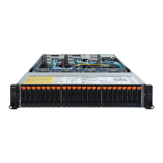
Front View
Rear View
Front Panel LED and Buttons
Rear System LAN Leds
Hard Disk Drive Leds
Power Supply Unit LED
Chapter 3 System Hardware Installation
Removing and Installing the Chassis Cover
Removing and Installing the Fan Duct
Removing and Installing the CPU and Heat Sink
Removing and Installing Memory
Eight-Channel Memory Configuration
Removing and Installing a Memory Module
DIMM Population Table
Removing and Installing the PCI Expansion Card
Removing and Installing the Hard Disk Drive
Installing and Removing an M.2 Solid State Drive
Replacing the Fan Assembly
Removing and Installing the Power Supply
Cable Routing (1 of 2)
Cable Routing (2 of 2)
Chapter 4 Motherboard Components
Motherboard Components
Jumper Settings 38
Chapter 1 BIOS Setup
Server Management
The Main Menu
System Time
Advanced Menu
Iscsi Configuration
Qlogic 577Xx/578Xx 10 Gb Ethernet BCM57810
Link Speed
VLAN Configuration
CPU Configuration
SATA Configuration
USB Configuration
AST2500 Super IO Configuration
Serial Port Console Redirection
Flow Control
PCI Subsystem Settings
Network Stack
CSM Configuration
Boot Option Filter
Option Rom Execution
Trusted Computing
Nvme Configuration
AMD CBS Menu
Zen Common Options
DF Common Options
UMC Common Options
NBIO Common Options
FCH Common Options
Chipset Setup Menu
North Bridge
Error Management
Server Management Menu
System Event Log
View FRU Information
BMC Network Configuration
Ipv6 BMC Network Configuration
Security Menu
Secure Boot
Key Management
Boot Menu
UEFI NETWORK Drive BBS Priorities
UEFI Application Boot Priorities
Save & Exit Menu
ABL POST Codes
Startprocessortestpoints
Memory Test Points
PMU Test Points
Original Post Code
CPU Test Points
Topology Test Points
Extended Memory Test Point
Gnb Earlier Init
PMU Test Points
ABL0 Test Points
ABL5 Test Points
Agesa POST Codes
Universal Post Code
0Xa1Xx] for CZ Only Memory Postcodes
S3 Interface Post Code
PMU Post Code
0Xa5Xx] Assigned for AGESA PSP Module
0Xa9Xx, 0Xaaxx] Assigned for AGESA NBIO Module
0Xacxx] Assigned for AGESA CCX Module
0Xadxx] Assigned for AGESA DF Module
0Xafxx] Assigned for AGESA FCH Module
BIOS POST Beep Code (AMI Standard)
PEI Beep Codes
DXE Beep Codes
BIOS Recovery Instruction
Advertisement
Quick Links
Download this manual
R281-Z91
R281-Z92
MZ91-FS0 Motherboard for AMD
EPYC
Series Processors Family
®
TM
Service Guide
Rev. 1.1
Table of
Contents
Previous
Page
Next
Page
1
2
3
4
5
Advertisement
Table of Contents
Need help?
Do you have a question about the R281-Z91 and is the answer not in the manual?
Ask a question
Questions and answers
Related Manuals for Gigabyte R281-Z91
Motherboard Gigabyte R281-Z92 Service Manual
Mz91-fs0 chipset (136 pages)
Motherboard Gigabyte R281-Z94 User Manual
Mz91-fs0 motherboard for amd® epyctm series processors family (145 pages)
Motherboard Gigabyte R282-Z90 User Manual
Mz92-fs0 motherboard with dual sockets for amd epyc 7002 series family processors (162 pages)
Motherboard Gigabyte R282-Z91 User Manual
Mz92-fs0 motherboard with dual sockets for amd epyc 7002 series family processors (162 pages)
Motherboard Gigabyte R282-Z92 User Manual
Mz92-fs0 motherboard with dual sockets for amd epyc 7002 series family processors (162 pages)
Motherboard Gigabyte R271-Z31 Service Manual
Sp3 socket motherboard for the amd epyc series processor family (142 pages)
Motherboard Gigabyte R282-Z96 User Manual
(143 pages)
Motherboard Gigabyte R281-2O0 Service Manual
(124 pages)
Motherboard Gigabyte R281-NO0 Service Manual
(124 pages)
Motherboard Gigabyte R281-N40 Service Manual
(124 pages)
Motherboard Gigabyte R281-3C0 Service Manual
Dual lga3647 sockets motherboard for intel scalable family processors (117 pages)
Motherboard Gigabyte R281-3C1 Service Manual
Dual lga3647 sockets motherboard for intel scalable family processors (117 pages)
Motherboard Gigabyte R281-3C2 Service Manual
Dual lga3647 sockets motherboard for intel scalable family processors (117 pages)
Motherboard Gigabyte R280-F2O Service Manual
Dual lga2011 sockets r3 motherboard for intel e5-2600 v3/v4 series processors (121 pages)
Motherboard Gigabyte R260-R3C Service Manual
Dual lga2011 sockets r3 motherboard for intel e5-2600 v3/v4 series processors (123 pages)
Motherboard Gigabyte R152-Z31 User Manual
Amd epyc™ 7003 up server system - 1u 4-bay (147 pages)
This manual is also suitable for:
R281-z92
Table of Contents
Print
Rename the bookmark
Delete bookmark?
Delete from my manuals?
Login
Sign In
OR
Sign in with Facebook
Sign in with Google
Upload manual
Upload from disk
Upload from URL


Need help?
Do you have a question about the R281-Z91 and is the answer not in the manual?
Questions and answers