
Subscribe to Our Youtube Channel
Related Manuals for Gigabyte R280-F2O


Summary of Contents for Gigabyte R280-F2O
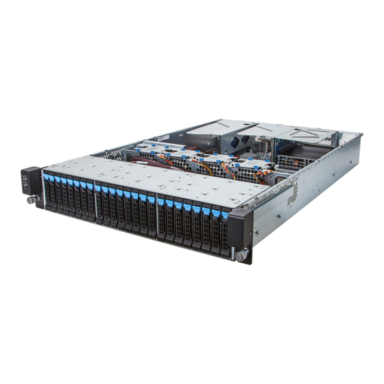
- Page 1 R280-F2O R280-G2O R280-A3C R280-F3C Dual LGA2011 sockets R3 motherboard for Intel E5-2600 V3/V4 series processors ® Service Guide Rev. 1.1...
- Page 2 GIGABYTE's prior written permission. Documentation Classifications In order to assist in the use of this product, GIGABYTE provides the following types of documentations: For detailed product information, carefully read the User's Manual.
- Page 3 Please note WHEN ORDERING SPARE PARTS, you should check the most up-to-date informationavailable on your regional web or channel. For whatever reason, if a part num- ber change is made,it will not be noted in the printed Service Guide. For GIGABYTE-AU- THORIZED SERVICEPROVIDERS, your GIGABYTE office may have a DIFFERENT part number code to thosegiven in the FRU list of this printed Service Guide.
-
Page 4: Table Of Contents
Table of Contents Box Contents ........................7 Safety, Care and Regulatory Information ................8 Chapter 1 Hardware Installation ................... 11 Installation Precautions .................. 11 Product Specifications ..................12 System Block Diagram ................... 14 Chapter 2 System Hardware Installation ..............15 Removing Chassis Cover ................16 Installing the CPU .................. - Page 5 Advanced Menu ..................... 44 5-2-1 Serial Port Console Redirection ................45 5-2-2 PCI Subsystem Settings ..................48 5-2-2-1 PCI Express Settings ....................50 5-2-3 Network Stack ......................52 5-2-4 CSM Configuration ....................53 5-2-5 Post Report Configuration ..................55 5-2-6 Trusted Computing ....................56 5-2-7 USB Configuration ....................57 5-2-8 Chipset Configuration .....................58 SIO Configuration ....................59...
- Page 6 Server Management Menu ................103 5-4-1 System Event Log ....................105 5-4-2 View FRU Information ..................106 5-4-3 BMC network configuration ..................107 Security Menu ....................108 5-5-1 Secure Boot menu ....................109 5-5-1-1 Key Management ....................110 Boot Menu ....................112 Save & Exit Menu ..................114 BIOS POST Codes ..................
-
Page 7: Box Contents
Box Contents R280-F2O/R280-G2O/R280-A3C System Driver CD Two CPU Heat Sinks Rai Kit • The box contents above are for reference only and the actual items shall depend on the product package you obtain. The box contents are subject to change without notice. -
Page 8: Safety, Care And Regulatory Information
Safety, Care and Regulatory Information Important safety information Read and follow all instructions marked on the product and in the documentation before you operateyour sys- tem. Retain all safety and operating instructions for future use. • The product should be operated only from the type of power source indicated on the rating label.* If your computer has a voltage selector switch, make sure that the switch is in the proper position foryour area. - Page 9 Federal Communications Commission (FCC) Statement Warning This is a class A product. In a domestic environment this product may cause radiointerfer- enceIn which case the user may be required to take adequate measures. This equipment has been tested and found to comply with the limits for a Class A digital device,pursuant to Part 15 of the FCC Rules.
- Page 10 California Proposition 65 Warning: This product contains a chemical, including lead , known to the State of California to cause cancer http://www.p65warnings.ca.gov/ Warning: This product contains a chemical, including lead , known to the State of California to cause birth defects or other reproductive harm.
-
Page 11: Chapter 1 Hardware Installation
Chapter 1 Hardware Installation Installation Precautions The motherboard/system contain numerous delicate electronic circuits and components which can become damaged as a result of electrostatic discharge (ESD). Prior to installation, carefully read the service guide and follow these procedures: • Prior to installation, do not remove or break motherboard S/N (Serial Number) sticker or warranty sticker provided by your dealer. -
Page 12: Product Specifications
AST2400 supports 16MB DDR3 VRAM ® Graphics Mass Storage 12 x 3.5” Hot-Swap HDDs (R280-A3C/R280-F3C/2.5" HDD supported) 24 x 2.5” Hot-Swap HDDs (R280-F2O/R280-G2O) Expander LSI SAS3x24 12Gb/s expander (R280-A3C Only) LSI SAS2x36 6Gb/s expander (R280-F2O/R280-G2O) System Fans 4 x 80x80x38mm /14900rpm 2 x USB 3.0 ports... - Page 13 (R280-F2O/ R280-A3C/ R280-F3C) Electrical 2 x Redundant 1600W 200-240VAC at 80 plus platinum Power Supply (R280-G2O) * GIGABYTE reserves the right to make any changes to the product specifications and product-related information without prior notice. Hardware Installation - 13 -...
-
Page 14: System Block Diagram
System Block Diagram Hardware Installation - 14 -... -
Page 15: Chapter 2 System Hardware Installation
Chapter 2 System Hardware Installation Pre-installation Instructions Perform the steps below before you open the server or before you remove or replaceany component. • Back up all important system and data files before performing any hardwareconfiguration. • Turn off the system and all the peripherals connected to it. • Locate the pin one of the CPU. -
Page 16: Removing Chassis Cover
Removing Chassis Cover Before you remove or install the system cover • Make sure the system is not turned on or connected to AC power. Follow these instructions to remove the system cover: Loosen and remove the screws securing the back cover. Loosen and remove the screws securing the front cover. -
Page 17: Installing The Cpu
Installing the CPU Read the following guidelines before you begin to install the CPU: • Make sure that the motherboard supports the CPU. • Always turn off the computer and unplug the power cord from the power outlet before installing the CPU to prevent hardware damage. -
Page 18: Installing The Heat Sink
Installing the Heat Sink Follow these instructions to install the heat sinks: Apply thermal compound evenly on the top of the CPU. Remove the protective cover from the underside of the heat sink. Place the heat sink(s) on top of the CPU and tighten the four positioning screws. WARNING! • When you are installing the heat sink on the CPU, ensure the cooling fan is facing the rear I/O of the system. -
Page 19: Installing The Memory
Installing the Memory Read the following guidelines before you begin to install the memory: • Make sure that the motherboard supports the memory. It is recommended that memory of the same capacity, brand, speed, and chips be used. • Always turn off the computer and unplug the power cord from the power outlet before installing the memory to prevent hardware damage. -
Page 20: Installing A Memory
2-4-2 Installing a Memory Before installing a memory module, make sure to turn off the computer and unplug the power cord from the power outlet to prevent damage to the memory module. Be sure to install DDR4 DIMMs on this motherboard. Follow these instructions to install the Memory: Insert the DIMM memory module vertically into the DIMM slot, and push it down. -
Page 21: Dimm Population Table
2-4-3 DIMM Population Table Speed (MT/s); Slot Per Channel (SPC) and DIMM Per Channel (DPC) Ranks Per Type DIMM and Data Width 1 Slot Per Channel 3 Slot Per Channel 2 Slot Per Channel 1DPC 1DPC 2DPC 1DPC 2DPC 3DPC SRx4 RDIMM 2400... -
Page 22: Installing The Pci Expansion Card
Installing the PCI Expansion Card • Voltages can be present within the server whenever an AC power source is connected. This voltage is present even when the main power switch is in the off position. Ensure that the system is powered-down and all power sources have been disconnected from the server prior to installing a PCI card. -
Page 23: Installing Add-On Card (Optional)
2-5-1 Installing Add-on Card (Optional) Follow these instructions to install Add-on card: Remove theriser bracket from the system following the steps outlined in 2-5 Installing the PCI Expansion Card. Remove the PCI bracket.. Insert the dedicated rear bracket and secure with screw. Engage the support bracket with mezzaine card and secure with screws. -
Page 24: Installing The Hard Disk Drive
Slide the blank into the bay until it locks into place. CAUTION! We strongly recommand using enterprise level hard disk drive in Gigabyte server system. For more information of recommanded HDDs, please visit Gigabyte website: https://www.gigabyte.com and serach for the specific product QVL from Support & Dowloads. -
Page 25: Replacing The Fan Assemblly
Replacing the FAN Assemblly Follow these instructions to replace the fan assembly: Lift up the fan assembly from the chassis. Reverse the previous step to install the replacement fan assembly. - 25 - Hardware Installation... -
Page 26: Replacing And Installing The Power Supply
Replacing and Installing the Power Supply Follow these instructions to replace the power supply: Disconnect the three power cables. With the existing power supply, pull up the power supply handle and press the retaining clip on the right side of the power supply along the direction of the arrow. At the same time, pull out the power supply by using its handle. -
Page 27: Installing Rail Into A Rack
Installing Rail Into A Rack Follow these instructions to install the rail into a rack: Release and detatch the inner rail from the slide. Attach the unit to the inner rail. Fix the outer rail/bracket assembly to the frame. Insert the unit to complete the installation. - 27 - Hardware Installation... -
Page 28: Chapter 3 System Appearance
Chapter 3 System Appearance Front View R280-F2O Decription Power button and LED Front Panel LEDs and buttons ID button and LED 2.5-inch hard disk drive (HDD) R280-A3C Decription Power button and LED Front Panel LEDs and buttons ID button and LED 3.5-inch hard disk drive (HDD) -
Page 29: Rear View
Rear View Decription Power supply fan Power supply module cord socket VGA port LAN ports ID switch button USB 2.0 ports RJ-45 COM port USB 3.0 ports LAN port PCI card bay - 29 - Hardware Installation... -
Page 30: Front Panel Led And Buttons
Front Panel LED and Buttons No. Name Color Status Critical Description Event System has power applied Green to itor ACPI S0 state Green Blink System is in ACPI S1 state (sleep mode) Power button System is not powered on or in and LED ACPI S5 state (power off) System is in ACPI S4 state... - Page 31 Green Solid On System is operating normally. Critical condition, may indicates the following: • Power module failure • System fan failure Solid On • Power supply voltage issue • System temperature/voltage issue • Current error/Processor error/ Critical memory error Amber Non-critical condition, may System indicates the following:...
-
Page 32: Rear System Lan Leds
Rear System LAN LEDs Name Color Status Description Yellow 1 Gbps data rate 1GbE Green 100 Mbps data rate Speed LED 10 Mbps data rate Link between system and 1GbE Green network or no access Link/ Blink Data transmission or receiving is occurring Activity LED No data transmission or receiving is occurring Hardware Installation... -
Page 33: Hard Disk Drive Leds
Hard Disk Drive LEDs Description Multi Color LEDs LED Active LED Active Green Amber HDD Access Blink HDD Locate HDD Failure HDD connected and rebuilding data Blink Blink (Alternative) Reserve - 33 - Hardware Installation... -
Page 34: Cable Routing
Cable Routing R280-F2O Suggest Cable Suggest Cable Front switch cable/Front LED cable HDD back plane board power cable Mini SAS cable #1 Mini SAS cable #2 System fan power cable HDD back plane board power cable HDD extension board power cable... -
Page 35: Chapter 4 Motherboard Components
Chapter 4 Motherboard Components MD90-FS0 Motherboard Components Item Code Description USB3_MLAN BMC Management LAN port (top) / USB 3.0 ports (bottom) COM1_USB2 RJ-45 COM port (top) / USB 2.0 ports (bottom)/ SW_ID ID switch button LAN1 LAN1 port LAN2 LAN2 port VGA port RISER_SLOT3 PCI Express x16 slot... - Page 36 CASE_OPEN Case open intrusion alert header SW_RAID Intel/LSI Software RAID Key jumper CLR_CMOS Clear CMOS jumper PSU1 Hot-plug PSU module connector#1 PSU2 Hot-plug PSU module connector#1 ATX1 14 pin main power connector 12V_GPU3_2 4 pin 12V power connector 12V_GPU3_1 8 pin power connector 12V_GPU2_2 4 pin 12V power connector 12V_GPU2_1...
- Page 37 Mini-SAS cable connector#1 supports SATA3 6Gb/s MINI_CN2 Mini-SAS cable connector#2 supports SATA3 6Gb/s SATA5 SATA3 6Gb/s connector SATA4 SATA3 6Gb/s connector RISER_1_2 PCI Express x16 slot (Gigabyte extension slot) BIOS_PWD Clearing Supervisor Password jumper BIOS_RCVR BIOS recovery jumper LED_BMC BMC firmware readiness LED RISER_1_1...
-
Page 38: Jumper Setting
Jumper Setting Jumper Code Jumper Setting 1-2 Close: Normal operation (Default setting) CLR_CMOS (Clearing CMOS Jumper) 2-3 Close: Clear CMOS data 1-2 Close: Stop an initial power on when BMC is not ready. S3_MASK (S3 Power On Select Jumper) 2-3 Close: Keep initial power on. (Default setting) 1-2 Close: Normal operation (Default setting) ME_UPDATE (ME Update Jumper) -
Page 39: Chapter 5 Bios Setup
Chapter 5 BIOS Setup BIOS (Basic Input and Output System) records hardware parameters of the system in the EFI on the motherboard. Its major functions include conducting the Power-On Self-Test (POST) during system startup, saving system parameters and loading operating system, etc. BIOS includes a BIOS Setup program that allows the user to modify basic system configuration settings or to activate certain system features. - Page 40 Main This setup page includes all the items in standard compatible BIOS. Advanced This setup page includes all the items of AMI BIOS special enhanced features. (ex: Auto detect fan and temperature status, automatically configure hard disk parameters.) ...
-
Page 41: The Main Menu
The Main Menu Once you enter the BIOS Setup program, the Main Menu (as shown below) appears on the screen. Use arrow keys to move among the items and press <Enter> to accept or enter other sub-menu. Main Menu Help The on-screen description of a highlighted setup option is displayed on the bottom line of the Main Menu. - Page 42 BIOS Information Porject Name Display the project name information. Porject Version Display version number of the BIOS setup utility. BIOS Build Date and Time Displays the date and time when the BIOS setup utility was created. BMC Information BMC Firmware Version Display BMC firmware version information.
- Page 43 Onboard LAN Information LAN1/LAN2/LAN3/LAN4 MAC Address Display LAN1/LAN2/LAN/LAN4 MAC address information. System Date Set the date following the weekday-month-day- year format. System Time Set the system time following the hour-minute- second format. - 43 - BIOS Setup...
-
Page 44: Advanced Menu
Advanced Menu The Advanced menu display submenu options for configuring the function of various hardware components. Select a submenu item, then press Enter to access the related submenu screen. BIOS Setup - 44 -... -
Page 45: Serial Port Console Redirection
5-2-1 Serial Port Console Redirection - 45 - BIOS Setup... - Page 46 COM1/Serial Port for Out-of-Band Management EMS Console Redirection Settings Console Redirection (Note) Select whether to enable console redirection for specified device. Console redirection enables users to manage the system from a remote location. Options available: Enabled/Disabled. Default setting is Disabled. Console Redirection Settings Terminal Type Select a terminal type to be used for console redirection.
- Page 47 Options available: None/Even/Odd/Mark/Space. Default setting is None. Stop Bits Stop bits indicate the end of a serial data packet. (A start bit indicates the beginning). The standard setting is 1 stop bit. Communication with slow devices may require more than 1 stop bit. Options available: 1/2.
-
Page 48: Pci Subsystem Settings
5-2-2 PCI Subsystem Settings PCI Express Slot #1/#2/#3/#4/#5 I/O ROM When enabled, This setting will initialize the device expansion ROM for the related PCI-E slot. Options available: Enabled/Disabled. Default setting is Enabled. Onboard LAN#1/#2Controller Enable/Disable onboard LAN devices. Options available: Enabled/Disabled. Default setting is Enabled. Onboard LAN #1/#2 I/O ROM Enable/Disable onboard LAN devices and initialize device expansion ROM. - Page 49 SR-IOV Support If system has SR-IOV capable PCIe Devices, this option enables or disables Single Root IO Virtualization Support. Options available: Enabled/Disabled. Default setting is Disabled. PCI Express Settings Press [Enter] for configuration of advanced items. BIOS Setup - 49 -...
-
Page 50: Pci Express Settings
5-2-2-1 PCI Express Settings PCI Express Device Register Settings Relaxed Ordering Enable/DIsable PCI Express Device Relaxed Ordering feature. Options available: Enabled/Disabled. Default setting is Disabled. Extended Tag Wnen this feature is enabled, the system will allow device to use 8-bit Tag field as a requester. Options available: Enabled/Disabled. - Page 51 Link Training Timeout (us) Define the number of Microseconds software will wait before polling 'Link Training' bit in Link Status register. Press <+> / <-> keys to increase or decrease the desired values. Value rang is from 10 to 10000 us. Unpopulated Links When this item is set to 'Disable Link, the system will operate power save feature for those unpopulated PCI Express links.
-
Page 52: Network Stack
5-2-3 Network Stack Network stack Enable/Disable UEFI network stack. Options available: Enabled/DIsabled. Default setting is Disabled. Ipv4 PXE Support (Note) Enable/Disable Ipv4 PXE feature. Options available: Enabled/DIsabled. Default setting is Enabled. Ipv6 PXE Support (Note) Enable/Disable Ipv6 PXE feature. Options available: Enabled/DIsabled. Default setting is Enabled. PXE boot wait time (Note) Press <+>... -
Page 53: Csm Configuration
5-2-4 CSM Configuration Compatibility Support Module Configuration CSM Support Enable/Disable Compatibility Support Module (CSM) support. Options available: Enabled/Disabled. Default setting is Enabled. CSM16 Module Version Display CSM Module version information. Gate20 Active Upon Request: GA20 can be disabled using BIOS services. Always: Do not allow disabling GA20;... - Page 54 Option ROM execution Network Controls the execution UEFI and Legacy PXE OpROM. Options available: Do not launch/UEFI/Legacy. Default setting is Legacy. Storage Controls the execution UEFI and Legacy Storage OpROM. Options available: Do not launch/UEFI/Legacy. Default setting is Legacy. Video Controls the execution UEFI and Legacy Video OpROM.
-
Page 55: Post Report Configuration
5-2-5 Post Report Configuration Post Report Configuration Error Message Report Post Error Message Enable/Disable Info Error Message support. Options available: Enabled/Disabled. Default setting is Enabled. BIOS Setup - 55 -... -
Page 56: Trusted Computing
5-2-6 Trusted Computing Configuration Security Device Support Select Enabled to activate TPM support feature. Options available: Enabled/Disabled. Default setting is Disabled. Current Status Information Display current TPM status information. - 56 - BIOS Setup... -
Page 57: Usb Configuration
5-2-7 USB Configuration USB Configuration USB Devices: Display the USB devices connected to the system. XHCI Hand-off Enable/Disable XHCI (USB 3.0) Hand-off support. Options available: Enabled/Disabled. Default setting is Enabled. EHCI Hand-off Enable/Disable EHCI (USB 2.0) Hand-off function. Options available: Enabled/Disabled. Default setting is Disabled. USB Mass Storage Driver Support (Note) Enable/Disable USB Mass Storage Driver Support. -
Page 58: Chipset Configuration
5-2-8 Chipset Configuration Restore on AC Power Loss (Note) Defines the power state to resume to after a system shutdown that is due to an interruption in AC power. When set to Last State, the system will return to the active power state prior to shutdown. When set to Stay Off, the system remains off after power shutdown. -
Page 59: Sio Configuration
SIO Configuration BIOS Setup - 59 -... - Page 60 AMI SIO Driver Version Display the AMI SIO driver version information. Super IO Chip Logical Device(s) Configuration [*Active*] Serial Port 1 Press [Enter] for confuguration of advanced items. Serial Port 1 Configuration Use This Device When enabled allows you to configure the serial port 1 settings. When set to Disabled, displays no configuration for the serial port.
-
Page 61: Iscsi Configuration
5-2-10 iSCSI Configuration iSCSI Initiator Name Add an Attempts Press [Enter] for configuration of advanced items. Delete Attempts Press [Enter] for configuration of advanced items. Change Attempt Order Press [Enter] for configuration of advanced items. BIOS Setup - 61 -... -
Page 62: Intel Rc Setup Menu
Intel RC Setup Menu Intel RC Setup menu displays submenu options for configuring the function of North Bridge and South Bridge. Select a submenu item, then press Enter to access the related submenu screen. RC Revision Display Intel RC version information. - 62 - BIOS Setup... - Page 63 5-3-1 Processor Configuration BIOS Setup - 63 -...
-
Page 64: Processor Configuration
Processor Configuration Pre-Socket Configuration Press [Enter] for configuration of advanced items. Processor Socket/Processor ID/Processor Frequency/Processor Max Raito/ Processor Min Raio/Microcode Revision/L1 Cache RAM/L2 Cache RAM/L3 Cache RAM/ Processor 0/1Version Displays the technical specifications for the installed processor. Hyper-Threading [All] The Hyper Threading Technology allows a single processor to execute two or more separate threads concurrently. - Page 65 Direct Cache Access (DCA) Options available: Auto/Enabled/Disabled. Default setting is Auto. DCA Prefetch Delay Options available: Disabled/8/16/24/32/40/48/56/64/72/80/88/96/104/112. Default setting is 32. X2APIC Options available: Enabled/Disabled. Default setting is Disabled. AES-NI Enable/Disable AES-NI (Intel Advanced Encryption Standard New Instructions) support function. Options available: Enabled/Disabled.
- Page 66 5-3-1-1 Pre-Socket Configuration - 66 - BIOS Setup...
- Page 67 CPU Socket 0/1 Configuration Press [Enter] for configuration of advanced items. Cores Enabled (for CPU socket 0/1) Number of Cores to enable. 0 means all cores. 14 Cores is available. Press the numeric keys to adjust desired values. BIOS Setup - 67 -...
-
Page 68: Advanced Power Management Configuration
5-3-2 Advanced Power Management Configuration Advanced Power Management Configuration Power Technology Option available:Disable/Energy Efficient/Custom. Default setting is Energy Efficient. Config TDP Options available: Enabled/Disabled. Default setting is Disabled. CPU P State Control Press [Enter] for configuration of advanced items. CPU C State Control Press [Enter] for configuration of advanced items. -
Page 69: Cpu P State Control
5-3-2-1 CPU P State Control EIST (P-State) Conventional Intel SpeedStep Technology switches both voltage and frequency in tandem between high and low levels in response to processor load. Options available: Enabled/Disabled. Default setting is Enabled. Turbo Mode When this item is enabled, tje processor will automatically ramp up the clock speed of 1-2 of its processing cores to improve its performance. -
Page 70: Cpu C State Control
5-3-2-2 CPU C State Control Package C State Limit Configure state for the C-State package limit. Options available: C0/C1 state/C2 state/C6(non Retention) state/C6(Retention) state. Default setting is C6(non Retention) state. CPU C3/C6 Report Allows you to determine whether to let the CPU enter C3/C6 mode in system halt state. When enabled, the CPU core frequency and voltage will be reduced during system halt state to decrease power consumption. -
Page 71: Cpu T State Control
5-3-2-3 CPU T State Control ACPI T-States Enable/Disable CPU throttling by OS. Thorttling reduces power comsumption. Options available: Enabled/Disabled. Default setting is Enabled. BIOS Setup - 71 -... -
Page 72: Common Refcode Configuration
5-3-3 Common RefCode Configuration Common RefCode Configuration Isoc Mode Options available: Auto/Enabled/Disabled. Default setting is Auto. Numa (Non-Uniform Memory Access) Options available: Enabled/Disabled. Default setting is Enabled. - 72 - BIOS Setup... - Page 73 5-3-4 QPI Configuration BIOS Setup - 73 -...
-
Page 74: Qpi Configuration
QPI General Configuration Press [Enter] for configuration of advanced items. QPI Status Press [Enter] to view QPI status. Link Speed Mode Options available: Slow/Fast. Default setting is Fast. Link Frequency Select Options available: 6.4GB/s/8.0GB/s/9.6GB/s/Auto/Auto Limited. Default setting is Auto. - 74 - BIOS Setup... -
Page 75: Memory Configuration
5-3-5 Memory Configuration Integrated Memory Controller (iMC) Enforce POR Enable to enforce POR restrictions for DDR4 frequency and voltage programming. Options available: Enforce POR/Disabled/Enforce Stretch Goals. Default setting is Enforce POR. Memory Frequency Configure memory frequency. Options available: Auto/1333/1400/1600/1800/1867/2000/2133. Default setting is Auto. ECC Support Options available: Auto/Disabled/Enabled. - Page 76 Memory Map Press [Enter] for configuration of advanced items. Memory RAS Configuration Press [Enter] for configuration of advanced items. - 76 - BIOS Setup...
- Page 77 5-3-5-1 Memory Topology BIOS Setup - 77 -...
-
Page 78: Memory Thermal
5-3-5-2 Memory Thermal Set Throttling Mode Configure Thermal Throttling Mode. Select OLTT or CLTT mode. Options available: Disabled/CLTT Mode. Default setting is CLTT Mode. MEMHOT Throttling Mode Options available: Disabled/Output-only/Input-only. Default setting is Input-only. - 78 - BIOS Setup... -
Page 79: Memory Map
5-3-5-3 Memory Map Socket Interleave Below 4GB Splits the 0-4GB address space between two sockets, so that both sockets get a chunk of local memory below 4GB. Options available: Disabled/Enabled. Default setting is Disabled. Channel Interleaving Options available: Auto/1-way Interleave/2-way Interleave/3-way Interleave/4-way Interleave. Default setting is Auto. -
Page 80: Memory Ras Configuration
5-3-5-4 Memory RAS Configuration RAS Mode Enable/Disable RAS modes. Enabling Sparing and Mirroring is not supported. When this item is set to enabled, Sparing will be selected. Options available: Disable/Mirror/Lockstep Mode. Default setting is Disabled. Lockstep x4 DIMMs Options available: Auto/Disabled/Enabled. Default setting is Auto. Memory Rank Sparing Options available: Disabled/Enabled. -
Page 81: Iio Configuration
5-3-6 IIO Configuration IIO Configuration EV DFX Features Set this option to allow DFX Lock Bits to remain clear. Options available: Enabled/Disabled. Default setting is Disabled. IOAT Configuration Press [Enter] for configuration of advanced items. Intel VT for Directed I/O (VT-d) Press [Enter] for configuration of advanced items. -
Page 82: Ioat Configuration
5-3-6-1 IOAT Configuration IOAT Configuration Enable IOAT Control to enable/disable IOAT (Intel I/O Acceleration Technology) device. Options available: Enabled/Disabled. Default setting is Disabled. No Snoop Enable/Disable PCI Express Device No Snoop option. Options available: Enabled/Disabled. Default setting is Disabled. - 82 - BIOS Setup... -
Page 83: Intel Vt For Directed I/O (Vt-D)
5-3-6-2 Intel VT for Directed I/O (VT-d) Intel VT for Directed I/O (VT-d) VT-d Azalea VCp Optimizations Enable/Disable Azalea VCp optimizations. Options available: Enabled/Disabled. Default setting is Disabled. Intel VT for Directed I/O (VT-d) Enable/Disable Intel VT for Directed I/O (VT-d) support function. Options available: Enabled/Disabled. -
Page 84: Pch Configuration
5-3-7 PCH Configuration PCH Configuration PCH Devices Press [Enter] for configuration of advanced items. PCH sSATA Configuration Press [Enter] for configuration of advanced items. PCH SATA Configuration Press [Enter] for configuration of advanced items. USB Configuration Press [Enter] for configuration of advanced items. - 84 - BIOS Setup... -
Page 85: Pch Devices
5-3-7-1 PCH Devices PCH CRID Enable/Disable Intel Compatible Revision ID. Options available: Enabled/Disabled. Default setting is Disabled. BIOS Setup - 85 -... - Page 86 5-3-7-2 PCH sSATA Configuration - 86 - BIOS Setup...
-
Page 87: Pch Ssata Configuration
When SATA Type is set to IDE PCH sSATA Configuration sSATA Controller(s) Enable/Disable sSATA controller. Options available: Enabled/Disabled. Default setting is Enabled. Configure sSATA as Coonfigure on chip SATA type. IDE Mode: When set to IDE, the SATA controller disables its RAID and AHCI functions and runs in the IDE emulation mode. - Page 88 Alternate Device ID on RAID Enable /Disable Alternate Device ID on RAID mode. Options available: Enabled/Disabled. Default setting is Disabled. Please note that this option appears when HDD is in RAID Mode. sSATA Port 0/1/2/3 The category identifies sSATA type of hard disk that are installed in the computer. System will automatically detect HDD type.
-
Page 89: Sata Mode Options
5-3-7-2-1 SATA Mode Options When SATA Type is set to IDE/AHCI Mode SATA LED locate When this option is enabled, LED/SGPIO hardware is attached. Options available: Enabled/Disabled. Default setting is Enabled. BIOS Setup - 89 -... - Page 90 When SATA Type is set to RAID Mode SATA LED locate When this option is enabled, LED/SGPIO hardware is attached. Options available: Enabled/Disabled. Default setting is Enabled. Intel Rapid Recovery Technology Enable/Disable Intel Rapid Recovery Technology support function. Options available: Enabled/Disabled. Default setting is Enabled. RAID Option ROM UI banner Options available: Enabled/Disabled.
-
Page 91: Pch Sata Configuration
5-3-7-3 PCH SATA Configuration BIOS Setup - 91 -... - Page 92 When SATA Type is set to IDE PCH SATA Configuration SATA Controller(s) Enable/Disable sSATA controller. Options available: Enabled/Disabled. Default setting is Enabled. Configure sSATA as Coonfigure on chip SATA type. IDE Mode: When set to IDE, the SATA controller disables its RAID and AHCI functions and runs in the IDE emulation mode.
- Page 93 Support Aggressive Link Power Mana (Note) Enable PCH to aggressively enter link power state. Options available: Enabled/Disabled. Default setting is Enabled. Alternate Device ID on RAID Enable /Disable Alternate Device ID on RAID mode. Options available: Enabled/Disabled. Default setting is Disabled. Please note that this option appears when HDD is in RAID Mode.
-
Page 94: Sata Mode Options
5-3-7-3-1 SATA Mode Options When SATA Type is set to IDE/AHCI Mode SATA LED locate When this option is enabled, LED/SGPIO hardware is attached. Options available: Enabled/Disabled. Default setting is Enabled. - 94 - BIOS Setup... - Page 95 When SATA Type is set to RAID Mode SATA LED locate When this option is enabled, LED/SGPIO hardware is attached. Options available: Enabled/Disabled. Default setting is Enabled. Intel Rapid Recovery Technology Enable/Disable Intel Rapid Recovery Technology support function. Options available: Enabled/Disabled. Default setting is Enabled. RAID Option ROM UI banner Options available: Enabled/Disabled.
-
Page 96: Usb Configuration
5-3-7-4 USB Configuration USB Precondition Precondition work on USB host conteoller and root ports for faster enumeration. Options available: Enabled/Disabled. Default setting is Disabled. xHCI Mode Enable/Disable xHCI (USB 3.0) support function. Options available: Smart Auto/Enabled/Disabled. Default setting is Smart Auto. - 96 - BIOS Setup... -
Page 97: Miscellaneous Configuration
5-3-8 Miscellaneous Configuration Miscellaneous Configuration Active Video Select active Video type. Options available: Onboard Device/Offboard Device. Default setting is Offboard Device. BIOS Setup - 97 -... -
Page 98: Server Me Configuration
5-3-9 Server ME Configuration Greneral ME Configuration Operational Firmware Version Display Operational Firmware Version information. Recovery Firmware Version Display Recovery Firmware Version information. ME Firmware Features Display ME Firmware features information. ME Firmware Status #1/#2 Display ME Firmware status information. Current State (for ME Firmware) Display ME Firmware current status information. -
Page 99: Runtime Error Logging
5-3-10 Runtime Error Logging Runtime Error Logging System Errors Enable/Disable system error logging function. Options available: Enabled/Disabled. Default setting is Enabled. S/W Error Injection Support Enable/Disable software injection error logging function. Options available: Enabled/Disabled. Default setting is Disabled. Whea Settings Press [Enter] for configuration of advanced items. -
Page 100: Whea Setting
5-3-10-1 Whea Setting WHEA Support (Windows Hardware Error Architecture) Enable/Disable WHEA Support. Options available: Enabled/Disabled. Default setting is Enabled. - 100 - BIOS Setup... -
Page 101: Memory Error Enabling
5-3-10-2 Memory Error Enabling Memory Error Enabling Un-Correctable Errors disable Memory Options available: Enabled/Disabled. Default setting is Disabled. Memory corrected Errors enabling Options available: Enabled/Disabled. Default setting is Disabled. BIOS Setup - 101 -... -
Page 102: Pci/Pci Error Enabling
5-3-10-3 PCI/PCI Error Enabling PCI-Ex Error Enable Options available: Yes/No. Default setting is No. - 102 - BIOS Setup... -
Page 103: Server Management Menu
Server Management Menu FRB-2 Timer Enable/Disable FRB-2 timer (POST timer). Options available: Enabled/Disabled. Default setting is Disabled. FRB2 Timer timeout Configure the FRB2 Timer timeout. Options available: 3 minutes/4 minutes/5 minutes/6 minutes. Default setting is 6 minutes. Please note that this item is configurable when FRB-2 Timer is set to Enabled. FRB2 Timer Policy Configure the FRB2 Timer policy. - Page 104 System Event Log Press [Enter] for configuration of advanced items. View FRU Information Press [Enter] to view the advanced items. BMC network configuration Press [Enter] for configuration of advanced items. - 104 - BIOS Setup...
-
Page 105: System Event Log
5-4-1 System Event Log Enabling/Disabling Options SEL Components Change this to enable or disable all features of System Event Logging during boot. Options available: Enabled/Disabled. Default setting is Enabled. Erasing Settings Erasing SEL Choose options for erasing SEL. Options available: No/Yes, On next reset/Yes, On every reset. Default setting is No. When SEL is Full Choose options for reactions to a full SEL. -
Page 106: View Fru Information
5-4-2 View FRU Information The FRU page is a simple display page for basic system ID information, as well as System product information. Items on this window are non-configurable. R280-F2O R280-A3C - 106 - BIOS Setup... -
Page 107: Bmc Network Configuration
5-4-3 BMC network configuration BMC network configuration Select NCSI and Dedicated LAN Switch NCSI and dedicated LAN and send KCS command. Options available: Mode2(NSCI)/ Mode1 (Dedicated)/Do Nothing. Default setting is Do Nothing. Lan Channel 1 Configuration Address source Select to configure LAN channel parameters statically or dynamically (DHCP). Do nothing option willnot modify any BMC network parameters during BIOS phase. -
Page 108: Security Menu
Security Menu The Security menu allows you to safeguard and protect the system from unauthorized use by setting up access passwords. There are two types of passwords that you can set: • Administrator Password Entering this password will allow the user to access and change all settings in the Setup Utility. •... -
Page 109: Secure Boot Menu
5-5-1 Secure Boot menu The Secure Boot Menu is applicable when your device is installed the Windows 8 operatin system. ® Secure Mode Display the System secure mode state. Secure Boot Display the status of Secure Boot. Secure Boot Enable/Disable Secure Boot function. Options available: Enabled/Disabled. -
Page 110: Key Management
5-5-1-1 Key Management Default Key Provisioning Force the system to Setup Mode. This will clear all Secure Boot Variables such as Platform Key (PK), Key-exchange Key (KEK), Authorized Signature Database (db), and Forbidden Signaures Database (dbx). Options available: Enabled/Disabled. Default setting is Disabled. Enroll All Factory Default Keys Press [Enter] to install all factory default keys. - Page 111 Append Var to KEK Press [Enter] to load additional KEK from a storage devices for an additional db and dbx management. Authorized Signature Database (DB) Display the status of Authorized Signature Database. Delete DB Press [Enter] to delete the db from your system. Set new DB Press [Enter] to configure a new db.
-
Page 112: Boot Menu
Boot Menu The Boot menu allows you to set the drive priority during system boot-up. BIOS setup will display an error message if the legacy drive(s) specified is not bootable. Boot Configuration Setup Prompt Timeout Number of seconds to wait for setup activation key. 65535(0xFFFF) means indefinite waiting." Press the numberic keys to input the desired value. - Page 113 Network Device BBS Priorities Press Enter to configure the boot priority. Hard Drive BBS Priorities Press Enter to configure the boot priority. BIOS Setup - 113 -...
-
Page 114: Save & Exit Menu
Save & Exit Menu The Exit menu displays the various options to quit from the BIOS setup. Highlight any of the exit options then press Enter. Save Changes and Exit Saves changes made and close the BIOS setup. Options available: Yes/No. Discard Changes and Exit Discards changes made and exit the BIOS setup. - Page 115 Boot Override Press Enter to configure the device as the boot-up drive. UEFI: Built-in in EFI Shell Press <Enter> on this item to Launch EFI Shell from filesystem device. BIOS Setup - 115 -...
-
Page 116: Bios Post Codes
BIOS POST Codes PEI_CORE_STARTED 0x10 PEI_CAR_CPU_INIT 0x11 // reserved for CPU 0x12 - 0x14 PEI_CAR_NB_INIT 0x15 // reserved for NB 0x16 - 0x18 PEI_CAR_SB_INIT 0x19 // reserved for SB 0x1A - 0x1C PEI_MEMORY_SPD_READ 0x1D PEI_MEMORY_PRESENCE_DETECT 0x1E PEI_MEMORY_TIMING 0x1F PEI_MEMORY_CONFIGURING 0x20 PEI_MEMORY_INIT 0x21 // reserved for OEM use: 0x22 - 0x2F... - Page 117 DXE_SBRUN_INIT 0x62 DXE_CPU_INIT 0x63 //reserved for CPU 0x64 - 0x67 DXE_NB_HB_INIT 0x68 DXE_NB_INIT 0x69 DXE_NB_SMM_INIT 0x6A //reserved for NB 0x6B - 0x6F DXE_SB_INIT 0x70 DXE_SB_SMM_INIT 0x71 DXE_SB_DEVICES_INIT 0x72 //reserved for SB 0x73 - 0x77 DXE_ACPI_INIT 0x78 DXE_CSM_INIT 0x79 //reserved for AMI use: 0x7A - 0x7F //reserved for OEM use: 0x80 - 0x8F DXE_BDS_STARTED 0x90...
- Page 118 DXE_SETUP_INPUT_WAIT 0xAC DXE_READY_TO_BOOT 0xAD DXE_LEGACY_BOOT 0xAE DXE_EXIT_BOOT_SERVICES 0xAF RT_SET_VIRTUAL_ADDRESS_MAP_BEGIN 0xB0 RT_SET_VIRTUAL_ADDRESS_MAP_END 0xB1 DXE_LEGACY_OPROM_INIT 0xB2 DXE_RESET_SYSTEM 0xB3 DXE_USB_HOTPLUG 0xB4 DXE_PCI_BUS_HOTPLUG 0xB5 DXE_NVRAM_CLEANUP 0xB6 DXE_CONFIGURATION_RESET 0xB7 //reserved for AMI use: 0xB8 - 0xBF //reserved for OEM use: 0xC0 - 0xCF //PEI_STATUS_CODE //Errors //Regular boot PEI_MEMORY_INVALID_TYPE 0x50...
- Page 119 //S3 Resume PEI_MEMORY_S3_RESUME_FAILED 0xE8 PEI_S3_RESUME_PPI_NOT_FOUND 0xE9 PEI_S3_BOOT_SCRIPT_ERROR 0xEA PEI_S3_OS_WAKE_ERROR 0xEB //reserved for AMI use: 0xEC - 0xEF // DXE_STATUS_CODE DXE_CPU_ERROR 0xD0 DXE_NB_ERROR 0xD1 DXE_SB_ERROR 0xD2 DXE_ARCH_PROTOCOL_NOT_AVAILABLE 0xD3 DXE_PCI_BUS_OUT_OF_RESOURCES 0xD4 DXE_LEGACY_OPROM_NO_SPACE 0xD5 DXE_NO_CON_OUT 0xD6 DXE_NO_CON_IN 0xD7 DXE_INVALID_PASSWORD 0xD8 DXE_BOOT_OPTION_LOAD_ERROR 0xD9 DXE_BOOT_OPTION_FAILED 0xDA DXE_FLASH_UPDATE_FAILED 0xDB...
-
Page 120: Bios Post Beep Code
BIOS POST Beep code 5-9-1 PEI Beep Codes # of Beeps Description Memory not Installed. Memory was installed twice (InstallPeiMemory routine in PEI Core called twice) Recovery started DXEIPL was not found DXE Core Firmware Volume was not found Recovery failed S3 Resume failed Reset PPI is not available 5-9-2 DEX Beep Codes... -
Page 121: Bios Recovery Instruction
5-10 BIOS Recovery Instruction The system has an embedded recovery technique. In the event that the BIOS becomes corrupt the boot block can be used to restore the BIOS to a working state. To restore your BIOS, please follow the instructions listed below: Recovery Instruction: Change xxx.ROM to amiboot.rom.
Need help?
Do you have a question about the R280-F2O and is the answer not in the manual?
Questions and answers