
Related Manuals for Seakeeper 9


Summary of Contents for Seakeeper 9
- Page 1 INSTALLATION MANUAL *THIS MANUAL ALSO COVERS THE SEAKEEPER 7HD MODEL* Rev 6 JAN 2017...
- Page 2 Product: Document #: Rev: INSTALLATION MANUAL SEAKEEPER 9 / 7HD 90222 SEAKEEPER 9 / 7HD INSTALLATION MANUAL JANUARY 2017 Contents: Section 1 – Mechanical Installation & PC-120 Guide Section 2 – Electrical Installation Section 3 – Cooling Installation Section 4 – Startup Section 5 –...
- Page 3 This document is intended to give details and guidance to a boat builder or equipment installer to install the Seakeeper 9. The Seakeeper is capable of producing loads up to 17.09KN (3,842 lbs.) at each of the four mounts and careful consideration should be given to foundation design to insure it is capable of transferring these loads into the hull.
- Page 4 While handling / installing the Seakeeper assembly, do not allow electrical fittings that exit bottom of the Seakeeper enclosure to come in contact with any surface or object as this could damage the fittings and potentially affect the vacuum integrity of the enclosure.
- Page 5 SEAKEEPER 9 / 7HD 90222 3 of 20 Section 1: MECHANICAL INSTALLATION ZINC ANODE LOCATIONS VIEWS SHOWING RECOMMENDED CLEARANCES AROUND THE SEAKEEPER FOR USE OF HANDTOOLS, EASE OF MAINTENANCE, INSTALLATION, AND PROPER OPERATION. FIGURE 2 – INSTALLED SEAKEEPER CLEARANCE CONSIDERATIONS...
- Page 6 2” (53 mm) from the edge of the saddle beams to provide the necessary clearance for the swing of the motor power cable during the Seakeeper’s precession. Clearances aft of the Seakeeper are shown to provide access for regular...
- Page 7 Seakeeper noise has been measured under steady state conditions (no wave load) in Seakeeper's lab and in our test boat. The steady state noise is typically in the range of 70-75 dB un-weighted. As the frequencies emitting the highest sound pressures are low (like other marine machinery), it is recommended that the Seakeeper be installed in a machinery space that is already treated with soundproofing.
- Page 8 Section 1: MECHANICAL INSTALLATION Selection of Installation Method The Seakeeper 9 can be affixed to the hull structure using two methods 1) Bolt-In installation or 2) Bond-In (Saddle) installation. See figures below. OPTION 1- DIRECT FASTENING OF SEAKEEPER FOUNDATION TO SHIPS STRUCTURE Option 1 would be applied when a metal structure or laminated metal plates are available for attachment.
- Page 9 3) Remove packing materials that secure Seakeeper assembly inside the crate. 4) Attach spreader bar to the two lifting eyes located on the top of the Seakeeper enclosure. Stay clear of any other parts on the Seakeeper. The Seakeeper 9 weighs 549 kg (1210 lbs).
- Page 10 Seakeeper’s foundation. These plates have 4 holes located at the same centers as the mounting holes on the Seakeeper. The fixture locates the hole patterns at the proper spacing both in the fore-aft direction and the port- starboard direction.
- Page 11 INSTALLATION MANUAL SEAKEEPER 9 / 7HD 90222 9 of 20 Section 1: MECHANICAL INSTALLATION CAUTION: Tight clearances from cable guide bands to hull structure. See above figure for dimensions and reference Seakeeper drawing NO. 90225 for complete Seakeeper 9/7HD envelope.
- Page 12 1.5.2 Transfer of Holes to Boat Structure 1) Lower assembled fixture onto hull structure. The four areas where the feet of the Seakeeper will rest should be coplanar to within .06” (1.5 mm). See Figure 10. 3) Align fixture in desired location and transfer holes from fixture plate to the hull structure.
- Page 13 Check isolation gasket alignment by test fitting bolts without any obstructions. 2) Lower Seakeeper into position onto the hull foundation beams and align over drilled holes. 3) Install Seakeeper supplied fasteners Or Grade 8.8, M14-2.0 bolts to...
- Page 14 .13” inches (3 mm) for consistent adhesive bond gap. In addition, the four areas on top of the saddles on which the feet of the Seakeeper foundation will rest need to be co-planar within .06” inches (1.5 mm) to minimize potential distortion of Seakeeper support frame when installed.
- Page 15 Shear strength of the adhesive will be maximized if the cured thickness between the vessel structure and the Seakeeper saddles is at the thinner end of the adhesive manufacturer’s recommended range. Therefore, the fixture should be used to confirm that the overall dimensions of the foundations are square and level and that the adhesive gap is within Seakeeper’s recommended range of 1 to 3 mm (.04”...
- Page 16 Product: Document #: Rev: Page: INSTALLATION MANUAL SEAKEEPER 9 / 7HD 90222 14 of 20 Section 1: MECHANICAL INSTALLATION FIGURE 7 – SADDLE INSTALLATION FIXTURE ON NOTIONAL HULL STRUCTURE...
- Page 17 FIGURE 8 - INSTALLING FIXTURE ON HULL 2) Mask hull area (Fig 9) around foundation saddles for easy clean-up and to create outline of surface area to receive adhesive as (Fig 8). Insure that the bond gap is within the manufacturer’s recommended thickness, or 3 mm if using Plexus MA590.
- Page 18 8) Re-position installation fixture on girders and double-check that the adhesive gap is within the adhesive manufacturer’s maximum recommended thickness. Seakeeper recommends a maximum gap of 3 mm if using Plexus MA590. Note if bonding saddles to a metal structure, contact the adhesive manufacturer for hull...
- Page 19 .080” (2 mm) on top surface of hull as shown in Figure 11. Do not remove these screws. 3) Thoroughly clean with alcohol or acetone the inside surfaces of Seakeeper foundation saddles to remove any contaminates as shown in Figure 11. Use new paper towels for cleaning, not shop rags.
- Page 20 Note: This is a sample if using Plexus, if using another adhesive follow manufacturer’ recommendations. If using Plexus MA590 adhesive, the Seakeeper saddles should be installed when PC-120 is confirmed dry. 1) Assemble Plexus cartridge into either the manual or pneumatic gun as shown. Remove cap on cartridge and attach mixing tip.
- Page 21 Product: Document #: Rev: Page: INSTALLATION MANUAL SEAKEEPER 9 / 7HD 90222 19 of 20 Section 1: MECHANICAL INSTALLATION 5) Apply large bead Plexus adhesive to the hull structure as shown in the figure to the right. Apply approximately ½ to...
- Page 22 Allow adhesive to cure per manufacturer’s recommendations. Follow adhesive guidelines for curing time versus temperature prior to removing the fixture. 12) Bonding of Seakeeper saddles onto the hull is now complete. Remove installation fixture. 1.6.5 Installation of Seakeeper The four areas where the feet of the Seakeeper will rest should be coplanar to within .06”...
- Page 23 INSTRUCTIONS Product: All Document #: 90213 Process: Plexus PC- 120 Application Instructions Rev.: 1 Process Description: Instructions for use of surface conditioner Page 1 of 4 What is Plexus PC-120? • Plexus PC-120 is a dual function primer/conditioner designed to clean surface contamination and leave a thin coating of primer on specific metal surfaces.
- Page 24 INSTRUCTIONS Page 2 of 4 Product: ALL Document #: 90213 Process: Plexus PC- 120 Application Instructions Rev.: 1 1) Using too much PC-120 • Only a very thin coat should be left on the metal. You should be able to see a slight “pink” cast as illustrated below.
- Page 25 INSTRUCTIONS Page 3 of 4 Product: ALL Document #: 90213 Process: Plexus PC- 120 Application Instructions Rev.: 1 3) Not abrading corroded surfaces • As good as PC-120 is, it can’t help bonding performance if applied to a surface that is already corroded! •...
- Page 26 INSTRUCTIONS Page 4 of 4 Product: ALL Document #: 90213 Process: Plexus PC- 120 Application Instructions Rev.: 1 Remember these points! To avoid problems with Plexus PC-120: • Don’t use too much PC-120. Only a thin layer is needed. • Use a clean rag to wipe PC-120 off before it completely dries to remove surface contaminants it has cleaned.
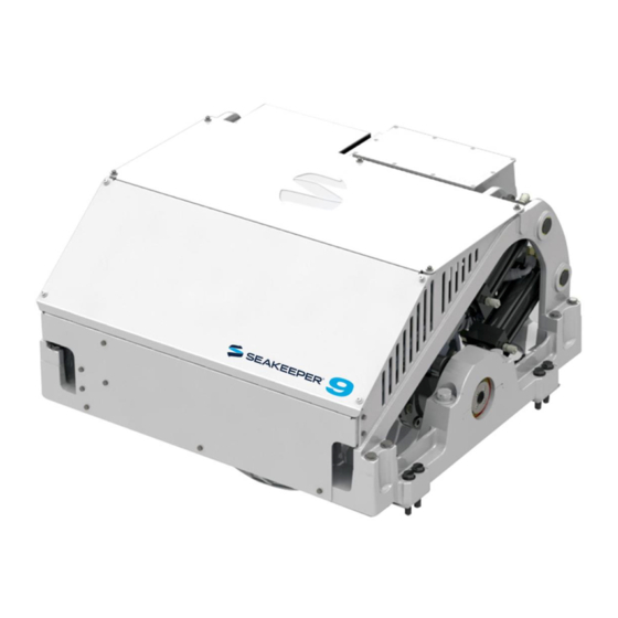
- Page 27 Helm Control Station Kit SEAKEEPER 9, Front Oblique View SEAKEEPER 9, Rear Oblique View CANvu 355 Display Interface Cable 24VDC Power Input Cable Terminator, Female Tee Adapter 20223 Color Display Display Interface Cable 25m Cable FIGURE 1 – ELECTRICAL EQUIPMENT FOR SEAKEEPER 9...
- Page 28 Precautions Each item of electrical equipment has specific mounting instructions. These instructions should be followed to insure proper function of the Seakeeper. Do NOT move Seakeeper mounted components from their locations or incorrect Seakeeper operation will result. 1. COLOR DISPLAY MOUNTING INSTRUCTIONS, SURFACE MOUNT a.
- Page 29 1. 230 VAC POWER SOURCE REQUIREMENTS a. 230 VAC (nominal), 1 Phase, 50/60 Hz, 20 Amps. b. With installations of more than one Seakeeper, a separate circuit breaker should be used for each Seakeeper Motor Drive Box 2. DRIVE BOX AC POWER INPUT CONNECTION INSTRUCTIONS CSA), 10’...
- Page 30 Section 2: ELECTRICAL INSTALLATION 3. DRIVE BOX AC POWER OUTPUT TO SEAWATER PUMP CONNECTION INSTRUCTIONS CSA) cable, 10’ (3m) length, Seakeeper supplied a. Cable: 3 x 14AWG (3 x 2.5 mm pre-installed. b. Pumps rated at 230 VAC, 5 Amps max., Customer-supplied.
- Page 31 Seakeeper operation. Do NOT cut CABLE 5 as it contains live voltage when the Seakeeper is in operation. The Seakeeper ships with CABLE 5 permanently sealed at end of cable with protective cap in the event it is not used.
- Page 32 24 VDC, 10 Amps. 2 x 12AWG (3 x 4.0 mm CSA) customer supplied. i. Install Seakeeper provided DC Power Input Cable, P/N: 20248 as CABLE 1. 1. Route CABLE 1 to DC Power Distribution Panel. 2. Terminate RED conductor to +24 VDC. Terminate BLACK conductor to 24V Rtn or Zero VDC.
- Page 33 Install CABLE 6 (10AWG or 6.0 mm , Customer supplied) from the M6 brass ground stud on the rear brace to a suitable vessel ground. Note: ONLY USE THIS LOCATION FOR GROUNDING THE SEAKEEPER TO THE VESSEL GROUND. GROUND STUD FIGURE 9 –...
- Page 34 .58 inch (14.8mm). b. CABLE 5 must be routed and installed in the vessel from the Seakeeper (female end) to the Tee Adapter (male end) at the Operator Station.
- Page 35 Operator Station Kit. Reference Drawings 90250 Helm Display 2 Operator Station Kit 90257 Seakeeper 9/7HD Cable Block Diagram (includes detail of 2nd Operator Station) 1. DETERMINE LOCATION OF 2 OPERATOR STATION a. The desired location of the 2 Operator Station must be determined with respect to the 1 Operator Station and the vessel arrangement.
- Page 36 Product: Document #: Rev: Page: INSTALLATION MANUAL SEAKEEPER 9 / 7HD 90222 10 of 11 Section 2: ELECTRICAL INSTALLATION 3. ROUTE 2 OPERATOR STATION CABLE a. A second CAN Cable Assembly (30243), also a 25 meter shielded cable, and the largest connector is a molded plug with maximum outer diameter of .58 inch...
- Page 37 Product: Document #: Rev: Page: INSTALLATION MANUAL SEAKEEPER 9 / 7HD 90222 11 of 11 Section 2: ELECTRICAL INSTALLATION Display Installation Template The following template is for mounting; before using this template, measure to ensure that the shown size is actual.
- Page 38 1 of 5 Section 3: COOLING INSTALLATION Introduction The Seakeeper 9 is shipped with the cooling circuit filled and ready for use. Only a quick confirmation of glycol level is required. Reference Drawings 90221 Seakeeper 9 Hardware Scope of Supply...
- Page 39 Product: Document #: Rev: Page: INSTALLATION MANUAL SEAKEEPER 9 / 7HD 90222 2 of 5 Section 3: COOLING INSTALLATION FIGURE 2 – SEAKEEPER 9 COOLING COMPONENTS...
- Page 40 In addition to initial operation at dock, new Seakeeper installations should be checked to be within the flow requirements while vessel is at speed. Flows higher than 8 GPM (30.3 LPM) could affect heat exchanger life.
- Page 41 Document #: Rev: Page: INSTALLATION MANUAL SEAKEEPER 9 / 7HD 90222 4 of 5 Section 3: COOLING INSTALLATION Mix 50% ethylene glycol with 50% distilled water in a clean container. Refer to Table 1 or glycol manufacturer’s literature for freezing points.
- Page 42 Connect seawater discharge (upper hose barb) to overboard drain. Use the same practices as other below waterline seawater plumbing. In addition to initial operation at dock, new Seakeeper installations should be checked for minimum 4 GPM (16 LPM) flow while vessel is at speed and when backing down. If no other method of confirming flow is available, discharge line may be temporarily diverted to a bucket.
- Page 43 2) Supply 208-230 VAC to Motor Drive Box at customer supplied electrical disconnect. 3) If sea water pump for the Seakeeper is not supplied though cable from Motor Drive Box, turn on the boat’s AC or DC dedicated circuit breaker that supplies power to the sea water pump.
- Page 44 Seakeeper will be free to move and precession can occur. 9) Verify that there are no alarms. If an ALARM is present it will be displayed. 10) Press the LOCK/UNLOCK Button to go from SEA to LOCK mode. Then press the Seakeeper ON/OFF Button to power the Seakeeper down.
-
Page 45: Installation Checklist
Mechanical Checklist (reference Installation Manual Section 1) Seakeeper Foundation Installed in Hull Foundation bolts torqued to specification Electrical Checklist (reference Seakeeper Drawing 90257 & Installation Manual Section 2) Mount Components Display (near helm) Connect Customer Supplied Cables ... - Page 46 Follow instruction in Section 4.1 of Installation Manual to turn off the Seakeeper AC & DC power and sea water pump may be turned off after the Seakeeper is turned off by placing the Seakeeper in LOCK mode and Turning the Seakeeper off ...
- Page 47 Spreader bar for lifting the Seakeeper Mechanical Hose clamps for seawater plumbing to 3/4" (19 mm) Cooling hose barb (2 per hose barb) M6 terminal lug for grounding Seakeeper at rear brace 2.3.1 Electrical Cable, 10 AWG, for grounding Seakeeper at rear 2.3.1...
Need help?
Do you have a question about the 9 and is the answer not in the manual?
Questions and answers