Table of Contents
Advertisement
Quick Links
SERVICE MANUAL
Ver 1.3 2001.11
Dolby noise reduction manufactured under license from
Dolby Laboratories Licensing Corporation.
" DOLBY " and the double-D symbol a are trademarks of
Dolby Laboratories Licensing Corporation.
Tape player section and general
Frequency response (aNR switch off)
30–18,000 Hz
Output
Headphones (2 REMOTE jack)
Load impedance 8–300 ohms
Power output
3mW + 3mW at DC operation
Power requirements
1.5V DC
Rechargeable battery (NC-6WM), 1.2 V, 600mAh, Ni-Cd One R6
(size AA) battery
Battery life (Approx. hours)
Rechargeable NC-6WM
Fully charged
Playback
Radio/TV reception
Sony alkaline LR6 (WM)
Playback
Radio/TV reception
Sony R6P (SR)
Playback
Radio/TV reception
Rechargeable NC-6WM
Sony alkaline LR6 (WM)
Used together
Playback
Radio/TV reception
Sony Corporation
9-923-252-12
2001K0500-1
Personal Audio Company
C 2001.11
Published by Sony Engineering Corporation
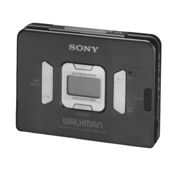
Photo: Black
SPECIFICATIONS
9
9
36
29
10
9
45
36
WM-FX855
Model Name Using Similar Mechanism
Tape Transport Mechanism Type
Dimensions
Approx. 108.7 × 80.0 × 23.5 mm (w/h/d)
Weight
Approx. 150 g (Main unit)
Approx. 210 g (incl. Headphones with remote control, Recharge-
able battery NC-6WM, Tape (C-60HF)
Radio section
Frequency range
Tourist model
FM : 76–90MHz
AM : 531–1,710kHz
TV : 1–12ch (Except Korean model.)
Korean model (Area setting : Eur)
FM : 87.5–108MHz
AM : 531–1,602kHz
Design and specifications are subject to change without notice.
RADIO CASSETTE PLAYER
E Model
Tourist Model
NEW
MT-WMEX655-125
– Continued on next page –
Advertisement
Table of Contents

Related Manuals for Sony WM-FX855


Summary of Contents for Sony WM-FX855
- Page 1 – Continued on next page – Sony R6P (SR) Playback Radio/TV reception Rechargeable NC-6WM Sony alkaline LR6 (WM) Used together Playback Radio/TV reception RADIO CASSETTE PLAYER Sony Corporation 9-923-252-12 2001K0500-1 Personal Audio Company C 2001.11 Published by Sony Engineering Corporation...
-
Page 2: Table Of Contents
LINE WITH MARK ! ON THE SCHEMATIC DIAGRAMS AND IN THE PARTS LIST ARE CRITICAL TO SAFE OPERATION. REPLACE THESE COMPONENTS WITH SONY PARTS WHOSE PART NUMBERS APPEAR AS SHOWN IN THIS MANUAL OR IN SUPPLEMENTS PUB- LISHED BY SONY. -
Page 3: Service Note
SECTION 1 SERVICE NOTE Service Mode Audio Board Mode for operating the mechanism section with the AUDIO board — Side A – opened. Battery terminal (—) 1. Setting 1) Refer to “Disassembly”, and remove the cabinet and open the AUDIO board. 2) Connect the motor and plunger to the AUDIO board using IC301 jumper wires. - Page 4 Rotation system Rotation system during FF. Rotation system during PLAY. gear (FR) motor pulley gear (TB) gear (NR) (FF: left side) gear (REEL) gear (REEL) gear (NR) (T side) (S side) (REW: right side/ FWD: left side) motor pulley gear (S) gear (REEL) gear (TB) (T side)
-
Page 5: General
SECTION 2 GENERAL LOCATION AND FUNCTION OF CONTROLS Tape player section and general • Main Unit • Headphones with Remote Control Left Right 1 OPEN button 8 Main unit : VOLUME knob 2 Information display Remote control : VOL knob 3 Contact for dry battery case 9 Åa (Tape direction), 4 Rechargeable battery case... -
Page 6: Disassembly
SECTION 3 DISASSEMBLY • This set can be disassembled in the order shown below. CASE ASS’Y LID ASS’Y CASSETTE (page 6) (page 7) AUDIO BOARD MECHANISM DECK (page 6) (page 7) Note: Follow the disassembly procedure in the numerical order given. CASE ASS’Y 3 Remove the case ass’y to direction of the arrow A . - Page 7 LID ASS’Y, CASSETTE 5 lid ass’y, cassette 4 serrat (IB lock) 4 serrat (IB lock) 2 tuner flexible board 3 screw (IB lock) 1 Open the cassette lid. MECHANISM DECK ornament ass’y, reel 2 Remove the mechanism deck to direction of the arrow A . –...
-
Page 8: Mechanical Adjustment
SECTION 5 SECTION 4 ELECTRICAL ADJUSTMENTS MECHANICAL ADJUSTMENTS PRECAUTION PRECAUTION 1. Clean the following parts with a denatured-alcohol-moistened 1. Specified voltage : 1.3 V (DC) swab: 2. Switch position a NR switch playback head pinch roller : OFF DIR MODE switch : a rubber belts capstan 2. - Page 9 • For the tracking adjustment, repeat is 2 or 3 times, then end TUNER SECTION with adjustment of trimmer capacitor. AM SECTION AM IF ADJUSTMENT Setup: BAND switch: AM Adjust for a maximum reading on level meter. Put the lead-wire 450 kHz antenna close to AM RF signal...
- Page 10 VCO Adjustment connection: frequency counter TUNER Board TP25 (19 kHz) — 150 k Ω VCO Adjustment Frequency counter Adjusting device Frequency display reading 78.00 MHz 19.00 kHz ± 0.05 kHz • Adjusting Location AM Frequency coverage Adjustment AM IF Adjustment FM IF Adjustment [TUNER Board] TP23...
-
Page 14: Audio Section
• Waveforms – AUDIO Section – – TUNER Section – 1 IC501 @ª (XIN) 1 T3 4 1V/DIV, 10 µs/DIV 1V/DIV, 100 ns/DIV 1.8 Vp-p 2.4 Vp-p 75 kHz 2 ns 2 IC701 5 (X0) 2 T3 1 2V/DIV, 200 ns/DIV 10V/DIV, 100 ns/DIV 20.4 Vp-p 4 Vp-p... -
Page 17: Audio Section
• IC Block Diagrams IC601 MM1279XVBE – AUDIO Section – IC301 TA2103F DET 2 PRE NF-L BASS PRE OUT-L AGC IN RF OUT MTL DRV-L – RIPPLE V REF FILTER BASE MTL DRV-R CH-A CH-B AGC DET PRE OUT-R PW GND PRE NF-R PW OUT-R F/R SW... -
Page 18: Tuner Section
– TUNER Section – IC1 TA8182FN IC2 TA2022AFN-EL – 29 –... -
Page 19: Ic Pin Function Description
6-6. IC PIN FUNCTION DESCRIPTION • AUDIO BOARD IC501 µPD17073GB-912-9EV (SYSTEM CONTROL (SUB)) Pin No. Pin Name Function RADIO CTL Output of RADIO control signal “ H ”: RADIO ON AM CTL Output of AM control signal TV CTL Output of TV control signal Output of clock to EEPROM —... - Page 20 Pin No. Pin Name Function — Not used for this set (Open) LCD13 Output of segment signal to the LCD — Not used for this set (Open) Output of chip enable control signal Input of request signal for MB89133LPFV communication —...
- Page 21 • AUDIO BOARD IC701 MB89133LPFV-G-418BND (SYSTEM CONTROL (MAIN)) Pin No. Pin Name Function AVCC — Power supply terminal (A/D converter) RESET Input of RESET signal MODE0 Test input terminal (fixed at “ L ”) MODE1 Test input terminal (fixed at “ L ”) —...
- Page 22 Pin No. Pin Name Function BEEP Output of beep sound (f=1.6 kHz) HOLDER Input of cassette cover open/close switch “ L ”: Close, “ H ”: Open — Not used for this set (Open) WAKE UP Input of interrupt signal for STOP mode cancel —...
-
Page 23: Exploded Views
Ver 1.2 1999. 04 SECTION 7 EXPLODED VIEWS NOTE: • -XX and -X mean standardized parts, so they • Items marked “*” are not stocked since they may have some difference from the original are seldom required for routine service. Some one. - Page 24 (2) AUDIO BOARD, COMPLETE SECTION S710 MT-WMEX655-125 ND501 Ref. No. Part No. Description Remark Ref. No. Part No. Description Remark 3-015-925-01 TERMINAL BOARD 3-928-465-01 DETENT, CASSETTE 3-375-114-71 SCREW (M1.7X3.5) 3-366-890-01 SCREW (M1.4) X-3374-330-1 TERMINAL BOARD ASSY (K) 3-007-282-01 TERMINAL BOARD (MINUS), BATTERY 3-015-926-01 LID, BATTERY CASE (BLACK) 3-016-087-01 COVER (SW) 3-015-926-41 LID, BATTERY CASE (GOLD)
- Page 25 (3) MECHANISM DECK SECTION (MT-WMEX655-125) PM901 M901 HP901 Ref. No. Part No. Description Remark Ref. No. Part No. Description Remark 3-011-277-01 COVER (B) (Y), MD X-3372-853-1 LEVER (FRG) ASSY 3-704-413-31 SCREW (M1.4X7.2) 3-007-432-01 SHEET (R), REFLECTION 3-007-434-01 PULLEY (REVERSE) * 120 3-010-272-01 BELT, RETAINER X-3372-850-1 PINCH LEVER (N) ASSY 3-007-427-01 SCREW (IB LOCK)
-
Page 26: Electrical Parts List
SECTION 8 AUDIO ELECTRICAL PARTS LIST NOTE: • Due to standardization, replacements in the • Items marked “*” are not stocked since they The components identified by mark ! or dotted line with mark parts list may be different from the parts speci- are seldom required for routine service. - Page 27 Ver 1.3 AUDIO Ref. No. Part No. Description Remark Ref. No. Part No. Description Remark C707 1-107-820-11 CERAMIC CHIP 0.1uF Q302 8-729-040-12 TRANSISTOR MUN5215T1 Q303 8-729-422-39 TRANSISTOR XN4404 C801 1-165-176-11 CERAMIC CHIP 0.047uF Q306 8-729-420-50 TRANSISTOR UN5215 C802 1-162-970-11 CERAMIC CHIP 0.01uF Q308 8-729-420-50 TRANSISTOR UN5215...
- Page 28 AUDIO TUNER Ref. No. Part No. Description Remark Ref. No. Part No. Description Remark R310 1-218-953-11 METAL CHIP 1.0K 1/16W < COMPOSITION CIRCUIT BLOCK > R314 1-218-949-11 METAL CHIP 1/16W R501 1-218-965-11 METAL CHIP 1/16W RB701 1-236-875-11 RES, NETWORK 100KX2 R502 1-218-981-11 METAL CHIP 220K...
- Page 29 TUNER Ref. No. Part No. Description Remark Ref. No. Part No. Description Remark 1-107-819-11 CERAMIC CHIP 0.022uF < DIODE > 1-164-315-11 CERAMIC CHIP 470PF 1-164-850-11 CERAMIC CHIP 18PF 8-719-053-30 DIODE MA2S357- (TX). SO 1-107-819-11 CERAMIC CHIP 0.022uF 8-719-053-30 DIODE MA2S357- (TX). SO 1-164-858-11 CERAMIC CHIP 22PF 8-719-053-30 DIODE MA2S357- (TX).
- Page 30 TUNER Ref. No. Part No. Description Remark Ref. No. Part No. Description Remark 1-218-949-11 METAL CHIP 1/16W 1-218-947-11 METAL CHIP 1/16W ACCESSORIES & PACKING MATERIALS 1-218-975-11 METAL CHIP 1/16W ********************************** 1-218-947-11 METAL CHIP 1/16W 1-475-182-11 REMOTE CONTROL UNIT (RM-WMF655) 1-218-957-11 METAL CHIP 2.2K 1/16W 1-528-543-11 BATTERY, NICKEL CADMIUM...
- Page 31 WM-FX855 MEMO – 42 –...
- Page 32 WM-FX855 E Model Tourist Model SERVICE MANUAL SUPPLEMENT-1 File this supplement with the service manual. Subject: 1. No interchangeability of motors due to change of mechanism deck 2. Caution when installing a new motor (ECN-WM800635) 1. No interchangeability of motors due to change of mechanism deck...
- Page 33 2. Caution when installing a new motor Always give a drop of Diamond Oil NT68 (7-661-018-18) to the hole of the shaft marked with when installing a new motor (X-3376-217-1). – 2 –...
- Page 34 WM-FX855 MEMO...
-
Page 35: Revision History
WM-FX855 REVISION HISTORY Clicking the version allows you to jump to the revised page. Also, clicking the version at the upper right on the revised page allows you to jump to the next revised page. Ver. Date Description of Revision 2001.11...
Need help?
Do you have a question about the WM-FX855 and is the answer not in the manual?
Questions and answers