Sony WM-FX193 Service Manual
Sony radio cassette player service manual
Hide thumbs
Also See for WM-FX193:
- Operating instructions (2 pages) ,
- Operating instructions (2 pages) ,
- Operating instructions (2 pages)
Table of Contents
Advertisement
WM-FX193/FX195
SERVICE MANUAL
Ver 1.0 2000.01
MICROFILM
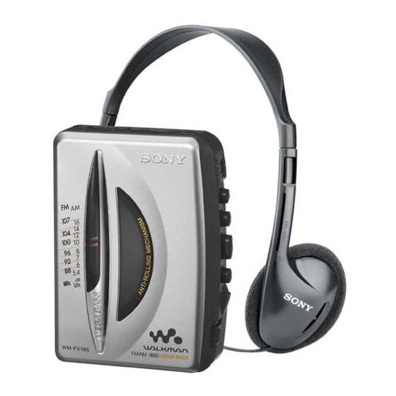
Photo : WM-FX195
SPECIFICATIONS
• Frequency range
FM: 87.5 - 108 MHz (Italy, Saudi Arabia)
87.6 - 107.9 MHz (Other countries)
AM: 526.5 - 1606.5 kHz (Italy, Saudi Arabia))
531 - 1602 kHz (Other countries)
• Power requirement
3 V DC batteries R6 (AA) x 2
• Dimensions
89.1 x 117.7 x 35.5 mm (w/h/d) incl. projecting parts and
controls
• Mass
Approx. 140 g/Approx. 220 g incl. batteries and a cassette
• Supplied accessories
Stereo headphones or Stereo earphones (1)/Belt clip (1)
Design and specifications are subject to change without notice.
Battery life (approximate hours)
Sony alkaline LR6 (SG)
playback
25
radio
55
* Measured value by the standard of EIAJ (Electronic
Industries Association of Japan). (Using a Sony HF series
cassette tape)
Note
• The battery life may shorten depending on the operation of
the unit.
Canadian Model
Chinese Model
Model Name Using Similar Mechanism
Tape Transport Mechanism Type
(EIAJ*)
Sony R6P (SR)
7.5
18
RADIO CASSETTE PLAYER
US Model
WM-FX193
AEP Model
E Model
WM-FX193/FX195
NEW
MF-WMFX195-114
Advertisement
Table of Contents

Related Manuals for Sony WM-FX193


Summary of Contents for Sony WM-FX193
- Page 1 Sony alkaline LR6 (SG) Sony R6P (SR) playback radio * Measured value by the standard of EIAJ (Electronic Industries Association of Japan). (Using a Sony HF series cassette tape) Note • The battery life may shorten depending on the operation of the unit.
-
Page 2: Table Of Contents
TABLE OF CONTENTS Specifications ................1 Flexible Circuit Board Repairing • Keep the temperature of the soldering iron around 270°C during 1. GENERAL repairing. • Do not touch the soldering iron on the same conductor of the Location and Function of Controls ........2 circuit board (within 3 times). -
Page 3: Disassembly
SECTION 2 DISASSEMBLY The equipment can be removed using the following procedure. Cabinet (rear) sub ASSY Main board Mechanism deck Belt, Capstan/reel moter (M901) Holder sub ASSY, Cassette Note : Follow the disassembly procedure in the numerical order given. 2-1. CABINET (REAR) SUB ASSY Holder sub ASSY, Cassette Claws Cabinet (front) -
Page 4: Mechanism Deck
2-3. MECHANISM DECK Mechanism deck 1 Insert the precision screwdriver (1.4 mm flat-blabe) in to the slit and release two claws. Cabinet (front) 2-4. BELT, CAPSTAN/REEL MOTOR (M901) 2 Screws (M1.4) Mechanism deck 3 Capstan/reel motor (M901) 1 Belt – 4 –... -
Page 5: Holder Sub Assy, Cassette
2-5. HOLDER SUB ASSY, CASSETTE Cabinet (front) 3 Move it away from projection Holder sub ASSY, Cassette 4 Spring (torsion) Cabinet (front) Holder sub ASSY, Cassette Cabinet (front) 2 Move it away from projection Holder sub ASSY, Cassette CAUTIONS DURING ASSEMBLY 1 Insert the dial indicator to the square hole of the cabinet (front) and align to the pointer. -
Page 6: Adjustments
SECTION 3 ADJUSTMENTS 3-1. MECHANICAL ADJUSTMENTS 3-2. ELECTRICAL ADJUSTMENTS PRECAUTION PRECAUTION 1. Clean the following parts with a denatured-alcohol-moistened • Supplied voltage : 2.5V. swab : • Switch and control position playback head pinch roller MEGA BASS switch : OFF (FX195) capstan rubber belt VOLUME control : maximum... - Page 7 • Repeat the procedures in each adjustment several times, and the TUNER SECTION 0 dB = 1µV frequency coverage and tracking adjustments should be finally AM Section done by the trimmer capacitors. BAND : AM < > : US, Canadian, E5, E6 model AM RF signal Put the lead-wire ] : Italian, Saudi Arabia model...
- Page 8 Adjustment Location : [MAIN BOARD] (Conductor side) CT1 : AM Tracking Adjustment CT4 : AM Frequency Coverage Adjustment CT2 : FM Tracking Adjustment CT3 : FM Frequency Coverage Adjustment L4 : AM Frequency Coverage Adjustment [MAIN BOARD] (Component side) T1 : AM IF Adjustment L2 : FM Tracking Adjustment L1 : AM Tracking Adjustment L3: FM Frequency Coverage Adjustment...
-
Page 9: Diagrams
WM-FX193/FX195 SECTION 4 DIAGRAMS 4-1. BLOCK DIAGRAM • Abbreviation • Signal path. : Canadian : FM : Saudi Arabia : AM : Chinese : PB : Indication of country of origin : No Indication of country of origin : Ukrine, Hungary, Czech... -
Page 10: Printed Wiring Boards
WM-FX193/FX195 4-2. PRINTED WIRING BOARDS Semiconductor Location Ref. No. Location D120 [MAIN BOARD] AVLS IC301 NORM -1 -2 DRY BATTERY LIMIT SIZE "AA" (IEC DESIGNATION R6) Q301 2PCS, 3V EXCEPT US, CND, Q302 E5, E6 MODEL EXCEPT E, E9, CH, EA MODEL... -
Page 11: Schematic Diagram
WM-FX193/FX195 4-3. SCHEMATIC DIAGRAM Note: • All capacitors are in µF unless otherwise noted. pF: µµF 50 WV or less are not indicated except for electrolytics and tantalums. • All resistors are in Ω and W or less unless otherwise specified. -
Page 12: Exploded Views
SECTION 5 EXPLODED VIEWS NOTE : IC Block Diagrams. Ref. No. Part No. Description Remark Ref. No. Part No. Description Remark • -XX, -X mean standardized parts, so they • The mechanical parts with no reference • Abbreviation X-3378-185-1 CABINET (REAR) SUB ASSY 3-039-267-11 HOLDER, CASSETTE (FX195:CND,E5,E6) may have some difference from the original number in the exploded views are not... -
Page 13: Mechanism Section -1
5-2. MECHANISM SECTION-1 (MF-WMFX195-114) HP901 M901 Ref. No. Part No. Description Remark Ref. No. Part No. Description Remark 3-013-560-11 BELT 3-920-996-01 SPRING (PINCH N) 3-703-816-31 SCREW (M1.4), SPECIAL HEAD HP901 1-500-641-11 HEAD, MAGNETIC (PLAYBACK) 3-921-042-01 GEAR(REEL) M901 1-763-073-11 MOTOR (CAPSTAN/REEL) (INCLUDING 3-703-816-73 SCREW (M1.4), SPECIAL HEAD PULLEY) X-3369-749-1 PINCH LEVER (N) ASSY... -
Page 14: Mechanism Section -2
5-3. MECHANISM SECTION-2 (MF-WMFX195-114) Ref. No. Part No. Description Remark Ref. No. Part No. Description Remark 3-921-797-01 WASHER 3-921-335-01 WASHER, LEVER 3-921-003-01 BEARING 3-920-990-01 SPRING (UD), COMPRESSION 3-938-628-02 SPRING (PLAY-CP) 3-921-050-01 GEAR (B) 3-920-999-01 GEAR (A) X-3372-619-1 WHEEL ASSY (P), CAPSTAN X-3376-169-1 CLUTCH ASSY 3-921-043-11 GEAR (D) 3-013-142-01 SPRING (FR-CP) -
Page 15: Electrical Parts List
SECTION 6 MAIN ELECTRICAL PARTS LIST NOTE : • Due to standardization, replacements in the • SEMICONDUCTORS When indicating parts by reference num- In each case, u : µ , for example : parts list may be different from the parts ber, please include the board. - Page 16 MAIN Ref. No. Part No. Description Remark Ref. No. Part No. Description Remark C304 1-164-360-11 CERAMIC CHIP 0.1uF < JACK > C305 1-124-584-00 ELECT 100uF J301 1-750-061-11 JACK,DC(POLARITY UNIFIED TYPE) C306 1-107-823-11 CERAMIC CHIP 0.47uF (DC IN 3V)(E,E9,CH,EA) C307 1-164-360-11 CERAMIC CHIP 0.1uF J302 1-565-287-11 JACK (i)
- Page 17 MAIN Ref. No. Part No. Description Remark Ref. No. Part No. Description Remark JR342 1-216-296-00 METAL CHIP 1/8W 1-216-815-11 METAL CHIP 1/16W JR343 1-216-296-00 METAL CHIP 1/8W 1-216-797-11 METAL CHIP 1/16W JR344 1-216-296-00 METAL CHIP 1/8W 1-216-815-11 METAL CHIP 1/16W 1-216-827-11 RES-CHIP 3.3K 1/16W...
- Page 18 WM-FX193/FX195 MAIN Ref. No. Part No. Description Remark Ref. No. Part No. Description Remark R308 1-216-845-11 METAL CHIP 100K 1/16W ACCESSORIES & PACKING MATERIALS R320 1-216-845-11 METAL CHIP 100K 1/16W ******************************* R321 1-216-841-11 METAL CHIP 1/16W R601 1-216-821-11 METAL CHIP...
Need help?
Do you have a question about the WM-FX193 and is the answer not in the manual?
Questions and answers