Sony WM-FX700 Service Manual
Radio cassette-corder
Hide thumbs
Also See for WM-FX700:
- Operating instructions (2 pages) ,
- Operating instructions (2 pages) ,
- Operating instructions (2 pages)
Table of Contents
Advertisement
Quick Links
Download this manual
See also:
Operating Instructions
WM-FX700/FX890/FX900
SERVICE MANUAL
Ver. 1.2 2005. 09
Radio section
Frequency range
FM;
87.5 - 108 MHz
AM;
531 - 1602 kHz
Tape section
Frequency response
Playback;
40 - 15000Hz
Output
Headphones (i) jack
Load impedance 8 - 300 Ω
General
Power requirements
1.5V
Rechargeable battery
One R6 (size AA) battery
Sony Corporation
9-961-230-03
Personal Audio Group
2005I02-1
Published by Sony Engineering Corporation
© 2005.09
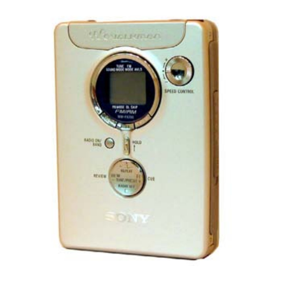
Photo: WM-FX700
Model Name Using Similar Mechanism
Tape Transport Mechanism Type
SPECIFICATIONS
Dimensions (w/h/d)
Approx.77.1 x 108.0 x 22.5 mm
1
3
(3
/
x 4
/
x
8
3
parts and controls
Mass
Approx.153g (5.4 oz) (main unit only)
Supplied accessories
AC power adaptor (1)
Battery case (1)
Stereo headphones or earphones with remote control (1)
Charging stand (1)
Rechargeable battery (NH-14WM (A), 1.2V, 1350 mAh (min),
Rechargable battery carrying case (1)
Carrying pouch (1)
Design and specifications are subject to change without notice.
RADIO CASSETTE-CORDER
US Model
Chinese Model
WM-FX700/FX890/FX900
Tourist Model
NEW
MF-WMFX890-162
29
/
inches) excl. projecting
32
WM-FX890
E Model
WM-FX890
Ni-MH) (1)
Advertisement
Table of Contents

Related Manuals for Sony WM-FX700


Summary of Contents for Sony WM-FX700
- Page 1 Rechargable battery carrying case (1) 1.5V Carrying pouch (1) Rechargeable battery One R6 (size AA) battery Design and specifications are subject to change without notice. RADIO CASSETTE-CORDER Sony Corporation 9-961-230-03 Personal Audio Group 2005I02-1 Published by Sony Engineering Corporation © 2005.09...
-
Page 2: Table Of Contents
(Caution: Some printed circuit boards may not come printed with LIST ARE CRITICAL TO SAFE OPERATION. REPLACE THESE the lead free mark due to their particular size.) COMPONENTS WITH SONY PARTS WHOSE PART NUMBERS APPEAR AS SHOWN IN THIS MANUAL OR IN SUPPLEMENTS PUBLISHED BY SONY. -
Page 3: Service Note
WM-FX700/FX890/FX900 SECTION 1 SERVICE NOTE 3. FF, REW modes This set detects the rotation of the idler gear (A) (side S) using the PH701 (photo reflector). The PH701 is mounted on the MAIN (1) Check that the preset state is set. - Page 4 WM-FX700/FX890/FX900 Slider (NR) Tape drive mechanism Tape drive mechanism in PLAY mode gear (FR ) (F F : left s ide) idler gear (A) (side T ) slider (NR ) gear (RE E L ) (side T ) motor pulley...
-
Page 5: General
WM-FX700/FX890/FX900 SECTION 2 GENERAL This section is extracted from instruction manual. • LOCATION OF CONTROLS... -
Page 6: Disassembly
WM-FX700/FX890/FX900 SECTION 3 DISASSEMBLY Note : Disassemble the unit in the order as shown below. “Case Block Assy” Main Board Belt (F2) Motor (M601) “Ornament “Lid Assy, “Pinch Lever Block Assy, “Holder (F) Assy” Magnetic Head (HP901) Cassette” (N) / (R) Assy”... -
Page 7: Main Board
WM-FX700/FX890/FX900 3-2. MAIN Board 2 Remove four solders of leaf switch. S701 3 Remove two solders of plunger solenoid. 5 two screws 6 MAIN board 5 screw (M1.4) 4 Remove four solders of motor. 1 Remove six solders of head flexible board. -
Page 8: Motor (M601)
WM-FX700/FX890/FX900 3-4. Motor (M601) 1 two screws (M1.4) 2 motor 3-5. “Lid Assy, Cassette” 1 screw (M1.4 × 2) 5 “lid assy, cassette” 2 two screws (M1.4 × 2) 3 Open the cassette lid. 4 shaft... -
Page 9: Ornament Block Assy, Reel
WM-FX700/FX890/FX900 3-6. “Ornament Block Assy, Reel” 4 claw 5 “ornament block assy, reel” 4 claw 3 boss 1 claw 1 claw 2 claw 3-7. “Holder (F) Assy” 2 shaft 7 bracket (cassette) assy 5 “lever (S), lock” 3 “lever (B), lock”... -
Page 10: Pinch Lever (N)/(R) Assy
WM-FX700/FX890/FX900 3-8. “Pinch Lever (N) / (R) Assy 1 claw 2 Remove the pinch lever (R) assy in the dereciton of the arrow. 4 Remove the pinch lever (N) assy in the direction of the arrow. 3 claw 3-9. Magnetic Head (HP901) -
Page 11: Mechanical Adjustment
WM-FX700/FX890/FX900 SECTION 4 SECTION 5 MECHANICAL ADJUSTMENT ELECTRICAL ADJUSTMENT PRECAUTION PRECAUTION Clean the following parts with a denatured-alcohol-moistened Specified voltage : 1.3 V (DC) swab: Setting playback head pinch roller SPEED CONTROL (RV602) : Center Value rubber belts capstan MONO/ST : FM STEREO Demagnetize the playback head with a head demagnetizer. - Page 12 WM-FX700/FX890/FX900 • Repeat the procedures in each adjustment several times, and TUNER SECTION 0 dB = 1µV the frequency coverage and tracking adjustments should be AM Section finally done by the trimmer capacitors. BAND : AM no mark : 10kHz step AM RF signal <...
- Page 13 WM-FX700/FX890/FX900 Adjustment Location : MAIN BOARD (SIDE B) L5 : AM tracking adjustment (VT) RV601 : Tape speed adjustment L1 : FM tracking adjustment ANT IN CT1 : AM tracking adjustment...
-
Page 14: Diagrams
WM-FX700/FX890/FX900 SECTION 6 DIAGRAMS Note for Printed Wiring Board and Schematic Diagrams Note on Schematic Diagram: Note on Printed Wiring Board: • All capacitors are in µF unless otherwise noted. pF: µµF • Y : parts extracted from the conductor side. -
Page 15: Block Diagram
WM-FX700/FX890/FX900 6-1. BLOCK DIAGRAM IC701 (1/2) SYSTEM FM/AM FRONT END (FM DISC) CONTROL IF DET, FM MPX QUAD LOUT (FM IF) RF IN IF IN BUFFER LCD701 ROUT R-CH PRE CTL LIQUID MUTE FMRFOUT COM1 Q305 CRYSTAL CUE REVIEW SWITCH... -
Page 16: Printed Wiring Board - Main Section (Side A)
WM-FX700/FX890/FX900 Ver 1.1 :Uses unleaded solder. 6-2. PRINTED WIRING BOARD — MAIN SECTION (SIDE A) — (SIDE A) MAIN BOARD • Semiconductor Location Ref. No. Location D101 D201 D302 D303 D304 D305 D401 IC601 IC703 IC901 Q305 Q306 Q404 Q405... -
Page 17: Printed Wiring Board - Main Section (Side B)
WM-FX700/FX890/FX900 :Uses unleaded solder. PRINTED WIRING BOARD — MAIN SECTION (SIDE B) — MAIN BOARD (SIDE B) RECHARGEABLE SPEED CONTROL S501-1 BATTERY S501-2 (TAPE DET) NH–14WM (ATS) 1PC. 1.2V 1350mAh PM901 (PLUNGER) TUNER/PRESET + DRY BATTERY SIZE "AA" ENTER (IEC DESIGNATION R6) 1PC, 1.5V... -
Page 18: Schematic Diagram - Main Section (1/3)
WM-FX700/FX890/FX900 Ver 1.1 6-3. SCHEMATIC DIAGRAM — MAIN SECTION (1/3) —... -
Page 19: Schematic Diagram - Main Section (2/3)
WM-FX700/FX890/FX900 6-4. SCHEMATIC DIAGRAM — MAIN SECTION (2/3) —... -
Page 20: Schematic Diagram - Main Section (3/3)
WM-FX700/FX890/FX900 6-5. SCHEMATIC DIAGRAM — MAIN SECTION (3/3) — • See page 23 for Pin Function Description. -
Page 21: Ic Block Diagrams
WM-FX700/FX890/FX900 6-6. IC BLOCK DIAGRAMS TA2154FN(EL) IC301 TA2123AF(EL) 36 35 32 31 28 27 26 – CAMP SW RF IN MT TC PW GND – BEEP BEEP OUT L AMS OUT OUT C MT SW OUT R – PW SW... - Page 22 WM-FX700/FX890/FX900 IC601 LB11675V-TLM W OUT PGND STARTING DETECTION POWER SPEED CURRENT SUPPLY DETECTION DETECTION VOLTAGE BIAS CIRCUIT V OUT U OUT START PGND VCCI V REF IN +...
-
Page 23: Ic Pin Function Discription
WM-FX700/FX890/FX900 6-7. IC Pin Function Description IC701 TC9328FA-CFX1766 (SYSTEM CONTROL) Pin No. Pin name Description 1 to 4 COM 1 to 4 LCD common drive 5 to 22 S 1 to 18 LCD segment drive MONO/STEREO Stereo/ Mono select terminal (H: STEREO / L: MONO) - Page 24 WM-FX700/FX890/FX900 Pin No. Pin name Description BATT DET Battery voltage detection signal input REMOTE KEY Remote commander key signal input AVLS CTL AVSL control signal output BST CTL BST signal output to TA2123AF MB/GRV CTL Mega bass/Groove control signal output to TA2123AF...
-
Page 25: Exploded Views
WM-FX700/FX890/FX900 Ver. 1.2 SECTION 7 EXPLODED VIEWS NOTE: • -XX, -X mean standardized parts, so they may • Color Indication of Appearance Parts • Accessories are given in the last of electrical have some differences from the original one. Example: parts list. -
Page 26: Mechanism Deck (Mf-Wmfx890-162)
WM-FX700/FX890/FX900 7-2. Mechanism Deck (MF-WMFX890-162) M901 PM901 HP901 Ref. No. Part No. Description Remarks Ref. No. Part No. Description Remarks X-3377-589-3 HOLDER (FA) ASSY/M 3-007-433-01 SHEET (N), REFLECTION X-3376-295-4 LEVER (R) ASSY, PINCH X-3377-584-5 CHASSIS ASSY (FA) 3-046-789-01 SPRING (HDA) -
Page 27: Electrical Parts List
WM-FX700/FX890/FX900 Ver 1.1 SECTION 8 MAIN ELECTRICAL PARTS LIST NOTE: • COILS • Due to standardization, replacements in the uH: µH parts list may be different from the parts specified in the diagrams or the components When indicating parts by reference number, •... - Page 28 WM-FX700/FX890/FX900 Ver 1.1 MAIN Ref. No. Part No. Description Remarks Ref. No. Part No. Description Remarks C406 1-125-837-91 CERAMIC CHIP 6.3V D304 8-719-422-37 DIODE MA8051-TX C407 1-117-919-11 TANTAL. CHIP 10uF 6.3V C408 1-164-943-11 CERAMIC CHIP 0.01uF D305 8-719-422-37 DIODE MA8051-TX...
- Page 29 WM-FX700/FX890/FX900 Ver 1.1 MAIN Ref. No. Part No. Description Remarks Ref. No. Part No. Description Remarks < PHOTO REFLECTOR > R107 1-208-635-11 RES-CHIP 1/16W R108 1-218-969-11 RES-CHIP 1/16W PH701 8-749-014-43 PHOTO REFLECTOR PR-20-T R109 1-218-945-11 RES-CHIP 1/16W < TRANSISTOR >...
- Page 30 WM-FX700/FX890/FX900 Ver 1.1 MAIN Ref. No. Part No. Description Remarks Ref. No. Part No. Description Remarks R613 1-218-990-11 SHORT CHIP < VARIABLE RESISTOR > R614 1-218-949-11 RES-CHIP 1/16W R615 1-218-973-11 RES-CHIP 1/16W RV301 1-225-684-21 RES, VAR, CARBON 30K/30K (wVOL) R616...
- Page 31 WM-FX700/FX890/FX900 Ver 1.1 Ref. No. Part No. Description Remarks 3-220-749-01 CASE, CARRYING 3-259-100-01 MANUAL, INSTRUCTION (SIMPLIFIED CHINESE,TRADITIONAL CHINESE, JAPANESE) (FX890: JE) 3-259-100-11 MANUAL, INSTRUCTION (ENGLISH,KOREAN) (FX890:KR,JE) 3-259-100-21 MANUAL, INSTRUCTION (ENGLISH,TRADITIONAL CHINESE)(FX890:E) 3-259-100-31 MANUAL, INSTRUCTION (ENGLISH,SIMPLIFIED CHINESE)(FX890:CH) 3-259-100-41 MANUAL, INSTRUCTION (ENGLISH)(FX890:US)
-
Page 32: Revision History
WM-FX700/FX890/FX900 REVISION HISTORY Clicking the version allows you to jump to the revised page. Also, clicking the version at the upper right on the revised page allows you to jump to the next revised page. Ver. Date Description of Revision 2003.09...
Need help?
Do you have a question about the WM-FX700 and is the answer not in the manual?
Questions and answers