Sony WM-FX888 Service Manual
Radio cassette player
Hide thumbs
Also See for WM-FX888:
- Operating instructions manual (60 pages) ,
- Operating instructions (2 pages)
Table of Contents
Advertisement
Quick Links
QQ
3 7 63 1515 0
SERVICE MANUAL
Ver 1.0 2001.11
Manufactured under license from Dolby Laborato-
ries.
"Dolby" and the double-D symbol are trademarks of
Dolby Laboratories.
Radio section
TE
L 13942296513
Frequency range
FM: 87.5 - 108 MHz
AM: 530 - 1 710 kHz (North, Central, and South America)
Tape section
Frequency response (Dolby NR off)
Playback: 40 - 15 000 Hz
Output
Headphones (i) jack
Load impedance 8 - 300 Ω
General
Power requirements
1.5 V
Rechargeable battery
One R6 (size AA) battery
Dimensions (w/h/d)
Approx. 108.4 × 77.7 × 23.0 mm
(4
Mass
Approx. 160 g (5.7 oz)
Supplied accessories
• AC power adaptor (1)
• Battery case (1)
• Stereo headphones or earphones with remote control (1)
• Charging stand (1)
• Rechargeable battery (NC-6WM, 1.2 V, 600 mAh, Ni-Cd) (1)
• Rechargeable battery carrying case (1)
• Carrying pouch (1)
Design and specifications are subject to change without notice.
www
.
Sony Corporation
9-873-396-01
2001K0500-1
Personal Audio Company
C 2001.11
Published by Sony Engineering Corporation
http://www.xiaoyu163.com
531 - 1 602 kHz (other countries)
× 3
×
3
⁄
1
⁄
29
⁄
inches)
8
8
32
x
ao
y
i
http://www.xiaoyu163.com
WM-FX888
8
Model Name Using Similar Mechanism
Tape Transport Mechanism Type
SPECIFICATIONS
Battery life (Approx. hours)
Q Q
3
6 7
1 3
Sony alkaline LR6 (SG)**
Tape playback
Radio reception
Rechargeable battery (NC-6WM)
Tape playback
Radio reception
Sony alkaline LR6 (SG)** and
Rechargeable NC-6WM
Tape playback
Radio reception
* Measured value by the standard of JEITA (Japan
Electronics and Information Technology Industries
Association). (Using a Sony HF series cassette tape)
**When using a Sony LR6 (SG) "STAMINA" alkaline dry
battery (produced in Japan).
Note
• The battery life may be shorter depending on the
operating condition, the surrounding temperature and
battery type.
u163
.
2 9
9 4
2 8
Chinese Model
Tourist Model
(JEITA*)
1 5
0 5
8
2 9
9 4
36
32
10
10
45
42
m
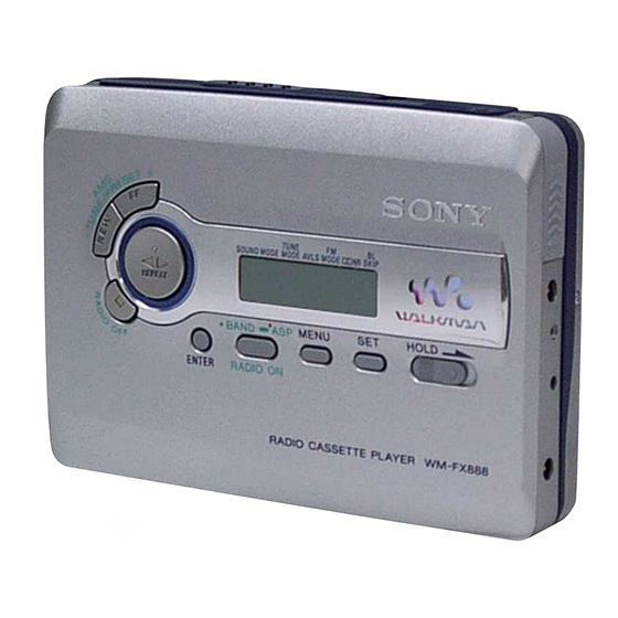
RADIO CASSETTE PLAYER
co
9 9
E Model
WM-FX675
MF-WMFX671-162
2 8
9 9
Advertisement
Table of Contents

Related Manuals for Sony WM-FX888


Summary of Contents for Sony WM-FX888
- Page 1 Supplied accessories Association). (Using a Sony HF series cassette tape) • AC power adaptor (1) **When using a Sony LR6 (SG) “STAMINA” alkaline dry • Battery case (1) battery (produced in Japan). • Stereo headphones or earphones with remote control (1) •...
-
Page 2: Table Of Contents
LINE WITH MARK 0 ON THE SCHEMATIC DIAGRAMS AND IN THE PARTS LIST ARE CRITICAL TO SAFE OPERATION. REPLACE THESE COMPONENTS WITH SONY PARTS WHOSE PART NUMBERS APPEAR AS SHOWN IN THIS MANUAL OR IN SUPPLEMENTS PUB- LISHED BY SONY. -
Page 3: Servicing Notes
WM-FX888 SECTION 1 3 7 63 1515 0 SERVICING NOTES This set detects the rotation of the idler gear (A) (side S) using the FF, REW modes PH1 (photo reflector). The PH1 is mounted on the MAIN board, (1) Check that the preset state is set. - Page 4 WM-FX888 3 7 63 1515 0 Slider (NR) Rotation system Rotation system during PLAY. gear (NR) (FWD : left side/ REV : right side) idler gear (A) (side S) idler gear (A) (side T) gear (REEL) (side S) gear (REEL) (side T)
-
Page 5: General
WM-FX888 SECTION 2 This section is extracted from instruction manual. 3 7 63 1515 0 GENERAL TUNE/PRESET + BAND• TUNE/PRESET – RADIO ON RADIO OFF – MENU RADIO ON/ BAND•OFF ENTER CHARGE HOLD SOUND HOLD MODE MENU FWD (forward) side... -
Page 6: Disassembly
WM-FX888 SECTION 3 DISASSEMBLY 3 7 63 1515 0 • This set can be disassembled in the order shown below. 3-1. DISASSEMBLY FLOW 3-2. CASE SECTION 3-6. CASSETTE LID SUB ASSY (page 6) (page 8) 3-3. MAIN BOARD 3-7. REEL ORNAMENT BLOCK ASSY... -
Page 7: Main Board
WM-FX888 3 7 63 1515 0 3-3. MAIN BOARD 1 Remove four solders of motor (M601). (1.7 × 3) 2 screw 2 screw (M1.4) (toothed lock) 3 MAIN board 1 Remove six solders of head flexible board. (1.7 × 3) -
Page 8: Motor (Capstan/Reel) (M601)
WM-FX888 3 7 63 1515 0 3-5. MOTOR (CAPSTAN/REEL) (M601) 1 two screws (M1.4) 2 motor (capstan/reel) (M601) L 13942296513 3-6. CASSETTE LID SUB ASSY 2 two screws (M1.4) 4 cassette lid sub assy 3 boss 2 screw (M1.4) u163 1 Open knob (open). -
Page 9: Reel Ornament Block Assy
WM-FX888 3 7 63 1515 0 3-7. REEL ORNAMENT BLOCK ASSY 2 claw 4 two claws 5 reel ornament block assy 3 boss L 13942296513 3-8. HOLDER (F) ASSY (/M) 4 screws (M1.4) 5 lock lever (S) (/M) 7 bracket (cassette) assy (/M) 8 Remove six solders of head flexible board. -
Page 10: Pinch Lever (Ra)/(Na) Assy
WM-FX888 3 7 63 1515 0 3-9. PINCH LEVER (RA)/(NA) ASSY 1 claw 2 Remove pinch lever (RA) assy in the direction of the arrow. 3 claw 4 Remove pinch lever (NA) assy holder (F) assy/M in the direction of the arrow. -
Page 11: Mechanical Adjustments
WM-FX888 SECTION 4 SECTION 5 3 7 63 1515 0 MECHANICAL ADJUSTMENTS ELECTRICAL ADJUSTMENTS PRECAUTION PRECAUTION 1. Clean the following parts with a denatured-alcohol-moistened 1. Specified voltage : 1.3 V (DC) swab: 2. Setting playback head pinch roller SOUND RV/MB/GRV : OFF... - Page 12 WM-FX888 3 7 63 1515 0 0 dB=1 µV AM IF ADJUSTMENT TUNER SECTION Adjust for a maximum reading on level meter [AM] 450 kHz Setting: function : RADIO AM VT VOLTAGE ADJUSTMENT BAND button : AM Adjustment Part Frequency Display Reading on Digital Voltmeter Put the lead-wire 1.5 ±...
-
Page 13: Diagrams
WM-FX888 SECTION 6 3 7 6 3 1 5 1 5 0 DIAGRAMS 6-1. BLOCK DIAGRAM – TUNER Section – 10.7MHz FM/AM IF AMP, FM/AM DET, MPX IC2 (1/2) FM RF AMP, MIX AMP, OSC 10.7MHz IF-IN FM IF AMP B.P.F. -
Page 14: Block Diagram - Main Section
WM-FX888 3 7 6 3 1 5 1 5 0 6-2. BLOCK DIAGRAM – MAIN Section – B+ SWITCH 2.5V B+ Q304 TUNER L-CH (Page 13) (Page 13) AUDIO MASTER AMP DOLBY NR AUDIO MASTER AMP (FWD/REV SELECT, PLAYBACK EQ AMP) -
Page 15: Note For Printed Wiring Board And Schematic Diagrams
WM-FX888 3 7 6 3 1 5 1 5 0 6-3. NOTE FOR PRINTED WIRING BOARD AND SCHEMATIC DIAGRAMS • Waveforms Note on Printed Wiring Board: Note on Schematic Diagram: 1 IC3 uf (XOUT) • All capacitors are in µF unless otherwise noted. pF: µµF •... -
Page 16: Printed Wiring Board - Main Board (Side A)
WM-FX888 6-4. PRINTED WIRING BOARD – MAIN Board (Side A) – 3 7 6 3 1 5 1 5 0 J701 • Semiconductor Location Ref. No. Location Ref. No. Location Ref. No. Location C-11 D803 D101 D-12 D804 Q304... -
Page 17: Printed Wiring Board - Main Board (Side B)
WM-FX888 6-5. PRINTED WIRING BOARD – MAIN Board (Side B) – 3 7 6 3 1 5 1 5 0 S901-1 S901-2 (TAPE DETECT) (ATS) • Semiconductor Location MAIN BOARD (SIDE B) Ref. No. Location Ref. No. Location Ref. No. -
Page 18: Schematic Diagram - Main Board (1/2)
WM-FX888 3 7 6 3 1 5 1 5 0 6-6. SCHEMATIC DIAGRAM – MAIN Board (1/2) – • • See page 15 for Waveform. See page 20 for IC Block Diagrams. 1 3 9 4 2 2 9 6 5 1 3... -
Page 19: Schematic Diagram - Main Board (2/2)
WM-FX888 3 7 6 3 1 5 1 5 0 6-7. SCHEMATIC DIAGRAM – MAIN Board (2/2) – • • See page 15 for Waveforms. See page 20 for IC Block Diagrams. 1 3 9 4 2 2 9 6 5 1 3... - Page 20 WM-FX888 3 7 6 3 1 5 1 5 0 • IC Block Diagrams IC302 NJM2185AV-TE2 IC1 TA7371AF-EL IC2 TA2022AFN-EL 15 14 REGULATOR SWITCH BIAS PILOT φ∠0° φ∠90° – CIRCUIT WEIGHT DIVIDE AF AMP DECODE AM IF AM DET...
-
Page 21: Ic Pin Function Description
WM-FX888 3 7 63 1515 0 6-8. IC PIN FUNCTION DESCRIPTION • IC3 TC9327AF-615 (SYSTEM CONTROLLER, LIQUID CRYSTAL DISPLAY DRIVER) Pin No. Pin Name Description 1 to 4 COM1 to COM4 Common drive signal output to the liquid crystal display... - Page 22 WM-FX888 3 7 63 1515 0 Pin No. Pin Name Description DDC2 CTL Power on/off control signal output of the DC/DC converter circuit “H”: power on Power on/off control signal output of the FM and AM circuit RADIO-CTL “L”: power on (FM or AM on), “H”: power off (tape on)
-
Page 23: Exploded Views
WM-FX888 SECTION 7 EXPLODED VIEWS 3 7 63 1515 0 NOTE: • Items marked “*” are not stocked since they • Abbreviation • -XX and -X mean standardized parts, so they may have some difference from the original are seldom required for routine service. Some CH : Chinese model one. -
Page 24: Chassis Section
WM-FX888 3 7 63 1515 0 7-2. CHASSIS SECTION MF-WMFX671-162 S901 L 13942296513 main section Ref. No. Part No. Description Remark Ref. No. Part No. Description Remark 3-345-648-71 SCREW (M1.4), TOOTHED LOCK X-3377-719-1 BRACKET (CASSETTE) ASSY (/M) X-3377-717-2 BRACKET ASSY (/M) -
Page 25: Main Section
WM-FX888 3 7 63 1515 0 7-3. MAIN SECTION L 13942296513 LCD1 Ref. No. Part No. Description Remark Ref. No. Part No. Description Remark 3-034-073-02 HOLDER (LCD) 3-031-460-01 SHEET (BT) u163 1-694-502-11 CONDUCTIVE BOARD, CONNECTION X-3377-726-2 TERMINAL BOARD ASSY (/M) -
Page 26: Mechanism Deck Section-1 (Mf-Wmfx671-162)
WM-FX888 3 7 63 1515 0 7-4. MECHANISM DECK SECTION-1 (MF-WMFX671-162) PM901 L 13942296513 mechanism deck section-2 Ref. No. Part No. Description Remark Ref. No. Part No. Description Remark 3-010-274-02 TABLE, REEL 3-029-281-01 GEAR, IDLER (B) 3-010-954-01 SPRING (BT), COMPRESSION... -
Page 27: Mechanism Deck Section-2 (Mf-Wmfx671-162)
WM-FX888 3 7 63 1515 0 7-5. MECHANISM DECK SECTION-2 (MF-WMFX671-162) M601 L 13942296513 mechanism deck section-3 Ref. No. Part No. Description Remark Ref. No. Part No. Description Remark 3-029-276-02 WASHER (STOPPER R) 3-007-428-01 WASHER (R) 3-029-289-01 WASHER 3-029-268-21 FLYWHEEL (R), INSERT 3-029-275-01 WASHER (STOPPER N) 3-029-765-01 SCREW (M1.4), TOOTHED LOCK... -
Page 28: Mechanism Deck Section-3 (Mf-Wmfx671-162)
WM-FX888 3 7 63 1515 0 7-6. MECHANISM DECK SECTION-3 (MF-WMFX671-162) HP901 L 13942296513 Ref. No. Part No. Description Remark u163 Ref. No. Part No. Description Remark X-3377-038-4 HOLDER (F) ASSY (/M) 3-046-789-01 SPRING (HDA) 3-033-757-01 SHEET (H) X-3377-363-1 LEVER (RA) ASSY, PINCH... -
Page 29: Electrical Parts List
WM-FX888 SECTION 8 3 7 63 1515 0 ELECTRICAL PARTS LIST MAIN NOTE: • Due to standardization, replacements in the • Items marked “*” are not stocked since they The components identified by mark 0 or dotted line with mark parts list may be different from the parts speci- are seldom required for routine service. - Page 30 WM-FX888 3 7 63 1515 0 MAIN Ref. No. Part No. Description Remark Ref. No. Part No. Description Remark C301 1-119-663-11 TANTALUM CHIP 47uF 2.5V D301 8-719-422-37 DIODE MA8051 C302 1-107-815-11 TANTALUM CHIP 2.2uF D302 8-719-422-37 DIODE MA8051 C303 1-164-360-11 CERAMIC CHIP 0.1uF...
- Page 31 WM-FX888 3 7 63 1515 0 MAIN Ref. No. Part No. Description Remark Ref. No. Part No. Description Remark < TRANSISTOR > 1-216-821-11 METAL CHIP 1/16W 1-216-845-11 METAL CHIP 100K 1/16W 8-729-037-89 TRANSISTOR 2SC4627J-C (TX).SO 8-729-028-69 TRANSISTOR 2SC4655-BC (TX)
- Page 32 WM-FX888 3 7 63 1515 0 MAIN Ref. No. Part No. Description Remark Ref. No. Part No. Description Remark R104 1-216-827-11 METAL CHIP 3.3K 1/16W 1-771-053-21 SWITCH, KEY BOARD (x, RADIO OFF) R105 1-216-823-11 METAL CHIP 1.5K 1/16W 1-771-053-21 SWITCH, KEY BOARD...
- Page 33 WM-FX888 3 7 63 1515 0 MEMO L 13942296513 u163 http://www.xiaoyu163.com...
- Page 34 WM-FX888 3 7 63 1515 0 REVISION HISTORY Clicking the version allows you to jump to the revised page. Also, clicking the version at the upper right on the revised page allows you to jump to the next revised page.
Need help?
Do you have a question about the WM-FX888 and is the answer not in the manual?
Questions and answers