
Related Manuals for Webasto Dual Top RHA-100


Summary of Contents for Webasto Dual Top RHA-100
- Page 1 Air heaters 03/2003 Integrated heater Workshop Manual Dual Top RHA-100 Dual Top RHA-101/102 10/2009 9019782B...
- Page 2 Webasto training course and have the appropriate technical documentation, special tools and special equipment. NEVER try to install or repair Webasto heating or cooling systems if you have not completed a Webasto training course, you do not have the necessary technical skills and you do not have the technical documentation, tools and equipment available to ensure that you can complete the installation and repair work properly.
-
Page 3: Table Of Contents
Dual Top Table of Contents Table of Contents Introduction ........................101 Contents and purpose ..........................101 1.1.1 Use of the integrated heaters ......................101 Meaning of signal words .........................101 Additional documentation to be used .....................101 Statutory regulations and safety instructions ...................101 1.4.1 Statutory regulations governing installation ...................101 1.4.2 General safety information ......................101 Technical data ........................201 Fault code output ......................301... - Page 4 Table of Contents Dual Top Repair ..........................701 General ..............................701 7.1.1 Work on stripped-down components ................... 701 7.1.1.1 Cleaning .......................... 701 7.1.1.2 Visual inspection ......................701 Dismantling ............................701 Assembling ............................708 Replacement of older to newer type Dual Top RHA 100 ................. 715 Packaging, storage and shipping ..................801 General ..............................
-
Page 5: Introduction
230 V electric systems. Installation and all other jobs carried ture deemed essential to highlight. out by none certified persons can cause personal injury to you, the Dual Top and the vehicle. In that case, Webasto will Additional documentation to be used refuse all liability. - Page 6 1 Introduction Dual Top...
-
Page 7: Technical Data
Dual Top 2 Technical data Technical data Except where limit values are specified, the technical data Fuel for Dual Top refer to the usual heater tolerances of ± 10 % at an ambient The diesel fuel specified by the manufacturer must be used. temperature of + 20 °C and at the rated voltage and in rated Class EL heating oil, L heating oil or PME (bio-diesel) must conditions. - Page 8 2 Technical data Dual Top Table 202: Technical data RHA 101/102 Heater Operation Dual Top RHA 101 Dual Top RHA 102 Type approval heater: e1 00 0195 e1 00 0195 EMC: e1 03 5000 e1 03 5000 Model Air heater with Air heater with evaporator burner evaporator burner...
-
Page 9: Fault Code Output
Abb. 301 Manual Control Panel sound of the heater). The manual Control Panel is used for RHA 100 heaters only. Deleting failures can also be done with the Webasto Thermo The heater is able to identify faults on individual Test PC-Diagnosis. - Page 10 3 Fault code output Dual Top Table 301: Fault messages manual Control Panel Number of Meaning Remedy RED flashes No communication between Control Panel and 1 First, remove fuses 15A and 5A. Then put in fuse 15A, heater, or error Control Panel followed by fuse 5A.
- Page 11 Dual Top 3 Fault code output Table 301: Fault messages manual Control Panel Number of Meaning Remedy RED flashes Overheating or exceeding gradient hot air 1 Ensure that hot air can flow freely, air intake and temperature sensor outlets are not blocked. Reset heater (by switching off for at least 5 sec.) 2 Check fuel pump cable and connectors.
-
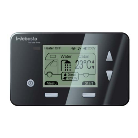
Page 12: Programmable Control Panel
5 seconds. Now the heater is reset. The programable Control Panel can be used with all types Deleting failures can also be done with the Webasto Thermo Dual Top heaters. Test PC-Diagnosis. - Page 13 Dual Top 3 Fault code output Table 302: Fault messages programmable Control Panel Message Meaning Remedy Message 08 Hot air motor fault: disconnection / 1 Check power supply: Failure heating air short circuit / fan speed out of range Fuse correct (fuse not damaged, 10A fuse used for ventilator / fan blocked PWM module) and functioning.
- Page 14 3 Fault code output Dual Top Table 302: Fault messages programmable Control Panel Message Meaning Remedy Message 17 Control unit (heater) fault / heater 1 Put heater back into service (see above this table) and Failure control unit locked restart heater. 2 Replace control unit.
- Page 15 Dual Top 3 Fault code output Table 302: Fault messages programmable Control Panel Message Meaning Remedy Message 34 One of the three overheating RHA 101/102: System overheated or switches detects too high 1 Check wiring harness relaybox to heater. relay circuit disconnected temperatures / overheating relay 2 Check the relay box and wiring connections.
- Page 16 3 Fault code output Dual Top Page for notes...
-
Page 17: General
4.2.1.1 Glowplug resistance test NOTE The resistance test must be carried out with an ohmmeter suitable for small resistance values or Webasto Thermo Test Table 401: Technical data water temperature sensor Diagnosis. Resistance... -
Page 18: Air Temperature Switch
4 Function tests Dual Top 4.2.1.4 Air temperature switch 4.2.1.6 Overheating protector The air temperature switch opens at 145 ± 5 °C. The overheating protector (temperature switch heat ex- changer) opens at 352 ± 15 °C and closes at 240 °C. 4.2.1.5 Water temperature switch The water temperature switch opens at 90 ±... -
Page 19: Circuit Diagrams
Dual Top 5 Circuit diagrams Circuit diagrams General Fig. 501 shows the heaters’ control unit. See Paragraph 5.2 for the legend of the circuit diagrams. How the electrical connections are to be made: Fig. 502 for RHA 100, Fig. 503 for RHA 101/102. Electrical connections Control Panel: Fig. - Page 20 5 Circuit diagrams Dual Top 1 Heater Dual Top 6 Fuse 10 A 2 Wiring harness 7 Fuse 15 A 3 Control Panel 8 Fuel pump 4 Vehicle’s service battery 9 Interior temperature sensor 5 Fuse 5 A 10 Wiring interior temperature sensor Fig.
- Page 21 X0 (2 poles) of interior temperature sensor to Control Panel X2 is for: – Webasto Thermo Test PC-diagnosis and – Webasto Telestart / Thermo Call (for optional programmable Control Panel). X4 (4 poles) of wiring harness to Control Panel Fig. 504 Electrical connections Manual Control Panel...
- Page 22 5 Circuit diagrams Dual Top Fig. 506 Wiring harness for Dual Top RHA 100 (older type, heater Ident. No. 9015314A and 9015314B)
- Page 23 Dual Top 5 Circuit diagrams Fig. 507 External wiring harness for Dual Top RHA 100 (newer type, heater Ident. No. 9015314C)
- Page 24 5 Circuit diagrams Dual Top Fig. 508 External wiring harness for Dual Top RHA 101/102...
- Page 25 Dual Top 5 Circuit diagrams Fig. 509 Internal wiring harness for Dual Top RHA 100/101/102...
- Page 26 5 Circuit diagrams Dual Top Legend for circuit diagram 1 Wiring harness vehicle 2 Wiring harness electric heater (not for RHA 100) 3 Vehicle’s service battery 4 Fuse 15 A 5 Fuse 10 A 6 Fuse 5 A 7 Interior temperature sensor 8 Dashboard LED (not for RHA 100) Cable cross-sections Cable colours...
-
Page 27: Servicing Work
Dual Top 6 Servicing work Servicing work General • check the following lines for signs of damage, to ensure that they are secure and clear: - exhaust, This section describes the servicing work that can be carried - combustion air, out on the heater when it is installed. -
Page 28: Installation
6 Servicing work Dual Top 6.7.1.2 Installation See Installation Instructions. 6.7.2 Control Panel, removal and installation 6.7.2.1 Manual version (for RHA 100) 1. Disconnect the battery. 2. Remove Control Panel as shown (see Fig. 601). 3. Disconnect the wiring harness plug X11. 4. - Page 29 Dual Top 7 Repair Repair General Dismantling This section describes the repair work that may be carried Loosen 2 screws T20 below hot and cold water connectors out on the Dual Top heater after it has been removed from 1 ~ 2 turns (just enough to move cover heating air blower). the vehicle.
- Page 30 7 Repair Dual Top Remove foam gasket cooling shell and air intake grill. Loosen 2 screws T30 of heating air blower assy with PWM module. Pull plug 4 poles of wiring harness out of PWM module (at side of motor heating air blower assy). Remove heating air blower assy.
- Page 31 Dual Top 7 Repair Loosen 4 screws T30 on bottom of Dual Top. Remove insulation combi-valve (top) and solenoid valve Push boiler incl. insulation out of housing. (bottom). Remove 2 parts insulation. Use flat (-) screwdriver to push down ring below solenoid valve and pull valve up to remove it from boiler.
- Page 32 7 Repair Dual Top Use flat (-) screwdriver to push down ring of connector hot Backside boiler: loosen hex nut SW 7mm that attaches wa- and cold water pipes and pull pipes up to remove them from ter temperature switch and water temperature sensor of boiler.
- Page 33 Dual Top 7 Repair Loosen 2 screws T10 that hold overheat switch to backside Remove exhaust gasket from exhaust and cooling air outlet. heat exchanger. Remove wires and cable fasteners from the ribs on the heat exchanger. Disconnect plug 2 poles of wiring overheating protector from internal wiring harness.
- Page 34 7 Repair Dual Top Disconnect 5 plugs of internal wiring harness from control Loosen 8 screws T20 to remove drive assy from heat ex- unit. changer. Loosen screw T20 that attaches brown wire to control unit. Remove flat gasket heat exchanger. Remove internal wiring harness.
- Page 35 Dual Top 7 Repair Loosen 2 screws T20 to remove clamping yoke from heat Loosen 2 screws T20 to remove burner tube assy and metal exchanger. crimp sealing from heat exchanger. Press grommet of wire glowplug inwards and guide plug through hole heat exchanger.
- Page 36 7 Repair Dual Top Assembling Align straight sides of burner tube assy and metal crimp sealing with bottom of heat exchanger. Fix with 2 screws T20. NOTE Position screws see drawing. NOTE Gaskets must always be renewed. Fix combustion air intake incl. connection gasket to drive assy with 3 screws T20.
- Page 37 Dual Top 7 Repair Attach flat gasket heat exchanger and drive assy to heat ex- Connect 2 plugs from thermo unit (Y1 and Y2, see Fig. 501) changer and fix with 8 screws T20. and 5 plugs of internal wiring harness (Y3, Y4, Y5, Y6 and Y7, see Fig.
- Page 38 7 Repair Dual Top Put gasket exhaust on exhaust and cooling air outlet. Fix overheating protector to backside heat exchanger with 2 screws T10. Connect plug 2 poles of wiring overheating protector to internal wiring harness. Fix wires to ribs heat exchanger using cable fasteners. Put 4 springs on heat exchanger to assure that clearance be- tween heat exchanger and boiler is spread evenly.
- Page 39 Dual Top 7 Repair Connect plug 8 poles of sensor wiring harness to internal Push air ventilation/overpressure valve as far as possible on wiring harness. connection of boiler. Put pink coloured silicon pad on 2 threaded studs M4 at Push hot water pipe as far as posible into air ventilation/ backside boiler and fix water temperature switch and water overpressure valve and cold water pipe into connection of temperature sensor of sensor wiring harness with hex nut...
- Page 40 7 Repair Dual Top Attach self-adhesive insulation combi-valve (top) and sole- Put 2 parts insulation on top and bottom of Dual Top (parts noid valve (bottom). are identical). NOTE NOTE Make sure that it’s possible to connect drain tube and wir- –...
- Page 41 Dual Top 7 Repair Connect plug 4 poles of internal wiring harness to PWM Fix hold metal plate (with air temperature sensor and air module. temperature switch) of sensor wiring harness to end cap Attach heating air blower assy to housing Dual Top with 2 with 2 screws T20.
- Page 42 Check that the heating air blower rotates freely before plac- Tightening torque: 6 Nm. ing heater back into vehicle. Use Webasto Thermo Test’s component test to run heating NOTE air blower with at 30, 60 and 90% for at least 30 seconds Service cap shall fit into grooves of grommets for wiring har- in each level.
- Page 43 7 Repair Replacement of older to newer type Dual Top RHA 100 Webasto recommends the following procedure when older 5 Connect 25 cm of new external wiring harness with 12- types heaters Dual Top RHA 100 are completely replaced by pin plug to old wiring harness (see Table 701 and Fig.
- Page 44 7 Repair Dual Top Page for notes...
- Page 45 8 Packaging, storage and shipping Packaging, storage and shipping General If the heater or its components are sent to Webasto AG for testing or repair, it must be cleaned and packed in such a way that it is protected against damage during handling, transport and storage.
- Page 46 8 Packaging, storage and shipping Dual Top Page for notes...
- Page 48 Webasto AG Kraillinger Strasse 5 82131 Stockdorf GERMANY http://dealers.webasto.com http://www.webasto.com Subject to modification © 2009 All Rights Reserved...
Need help?
Do you have a question about the Dual Top RHA-100 and is the answer not in the manual?
Questions and answers