Webasto Air Top 3500 Installation Instructions Manual
Hide thumbs
Also See for Air Top 3500:
- Installation instructions manual (112 pages) ,
- Workshop manual (49 pages) ,
- Operating instructions (4 pages)
Advertisement
Table of Contents
- 1 Table of Contents
- 2 Installation Instructions
- 3 Legal Provisions for Installation
- 4 Installation
- 5 Installation Example
- 6 Heating Air System
- 7 Fuel Supply
- 8 Combustion Air Supply
- 9 Exhaust Pipe
- 10 Electrical Connections
- 11 Circuit Diagrams
- 12 Initial Operation
- 13 Shut-Down on Faults
- 14 Technical Data
- 15 Drilling Template
- Download this manual
Advertisement
Table of Contents

Related Manuals for Webasto Air Top 3500


Summary of Contents for Webasto Air Top 3500
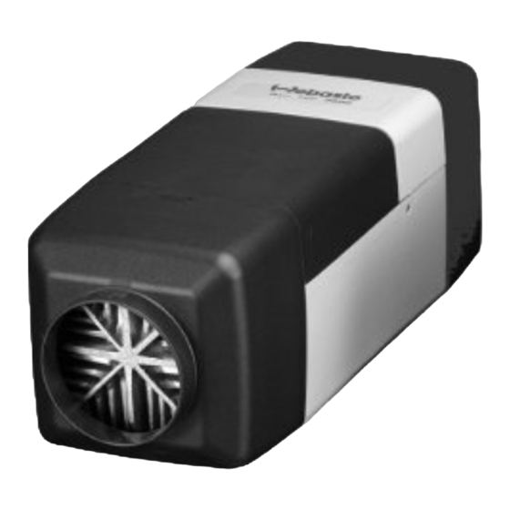
- Page 1 Visit www.butlertechnik.com for more technical information & downloads. Air Heaters Installation instructions Air Top 3500 Air Top 5000 Type Air Top 3500 B (Petrol Type Air Top 3500 D (Diesel) Type Air Top 5000 B (Petrol) Type Air Top 5000 D (Diesel) 12/1998...
-
Page 2: Table Of Contents
Visit www.butlertechnik.com for more technical information & downloads. Air Top 3500/5000 Table of Contents Page Installation Instructions Legal Provisions for Installation Installation Installation Example Heating Air System Fuel Supply Combustion Air Supply Exhaust Pipe Electrical Connections Circuit Diagrams Initial Operation... -
Page 3: Installation Instructions
Whenever the heater is removed it is imperative that be permanently vibration-proof. ~ S 305 Air Top 3500 B the gasket located underneath be replaced. “Exhaust gas pipe”: ~ S 306 Air Top 3500 D... - Page 4 Electric lines, switchgear and controlgear of the heater must be so arranged in the vehicle that their functioning Webasto will not assume any liability if the installation in- cannot be impaired under normal operating conditions. structions and the notes contained therein are not ob- served.
- Page 5 Visit www.butlertechnik.com for more technical information & downloads. Air Top 3500/5000 Scope of Application of the Air Heaters The Webasto Air Top 3500/5000 air heaters are designed to provide the following features: - for the heating of driver’s cabs, boats, trucks, small buses, vans and ambulance vehicles - defrosting the vehicle’s windows.
-
Page 6: Installation
Gasket Unobstructed installation to be ensured! Mounting the Heater When mounting the Air Top 3500/5000 heater, the M 6 nuts must be tightened to a torque of 6 Nm +1 Nm. The mounting dimensions as well as the space required Fig. -
Page 7: Installation Example
Visit www.butlertechnik.com for more technical information & downloads. Air Top 3500/5000 Heater control dial Heater Metering pump and damping device Fuel filter (accessory) Tank extracting device Exhaust silencer (accessory) Fuse Fig. 6: Installation example of air heater in the recirculating air mode... -
Page 8: Heating Air System
Air Top 3500 2,0 mbar (20 mm WH) It is not permissible to integrate the heater into the vehi- Air Top 3500 Volume Plus 3,0 mbar (30 mm WH) cle’s air ducting system. Air Top 5000 3,0 mbar (30 mm WH) Both recirculated-air and fresh-air operation is permissible. -
Page 9: Fuel Supply
Visit www.butlertechnik.com for more technical information & downloads. Air Top 3500/5000 Fuel Supply Fuel is extracted from the vehicle’s fuel tank or a separate fuel tank. The values relating to the permissible pressure at the fuel extraction point are shown in Fig. 8. - Page 10 In passenger cars, fuel may only be extracted with the spe- When installing the heater in vehicles with petrol injection cial Webasto fuel pickup (see Fig. 8) and as close to the systems it must be determined whether the fuel pump is tank as possible.
- Page 11 The proper connection of fuel lines using a hose is shown in Fig. 13. Check for leakage! Fig. 14: Metering Pump DP 2 Installation Position correct Air Top 3500/5000 D. 12-volt and 24-volt Diesel Fig. 12: Fuel Extraction From the Plastic Tank (Extraction Via Tank Fitting) clamp incorrect NOTE:...
-
Page 12: Combustion Air Supply
Combustion Air Intake and Exhaust Pipes If dirt in the fuel must be reckoned with, only Webasto filter, order no. 487 171, should be used. The filter is preferably Both pipes leading away from the heater are to be routed be installed in vertical position, where this is not possible, it in a downward pitch. -
Page 13: Exhaust Pipe
Visit www.butlertechnik.com for more technical information & downloads. Air Top 3500/5000 The lines must not point into the direction of travel. ± To ensure an angle of discharge of 90° 10°, it is re- quired that the pipe clamp be attached no more than 150 mm, from the exhaust pipe end Fig. -
Page 14: Electrical Connections
Goods (TRS) To connect the cable harness, remove the control unit When installing the Air Top 3500/5000 D heaters in ve- cover on the heater and connect the cable harness con- hicles for the transport of hazardous materials, the require- nectors with the control unit. - Page 15 Visit www.butlertechnik.com for more technical information & downloads. Air Top 3500/5000 Connection of Heater Control Element The cable harness is prepared for connection to the heater control. To withdraw the connector pull at the connector housing only. If the cable harness is pulled, the connector housing is locked (self-locking).
- Page 16 Visit www.butlertechnik.com for more technical information & downloads. Air Top 3500/5000 Jumper Terminal 15 Terminal 30 Terminal 58 Terminal 31 to isolate Fig.28: Connection diagram Air Top 3500/5000 ; only connection featuring a combination timer is shown. www.butlertechnik.com...
- Page 17 Visit www.butlertechnik.com for more technical information & downloads. Air Top 3500/5000 ϑ ϑ Fig.29: System circuit diagram Air Top 3500/5000, 12V/24V with Control Knob, legend see page 20 and 21 www.butlertechnik.com...
- Page 18 Visit www.butlertechnik.com for more technical information & downloads. Air Top 3500/5000 ϑ ϑ Fig.30: System circuit diagram Air Top 3500/5000, 12V/24V with Combination Timer , legend see page 20 and 21 www.butlertechnik.com...
- Page 19 Visit www.butlertechnik.com for more technical information & downloads. Air Top 3500/5000 ϑ ϑ Fig. 31: System circuit diagram Air Top 3500/5000, 12V/24V with Combination Timer and electrical battery disconnecting switch, legend see page 20 and 21 www.butlertechnik.com...
- Page 20 Visit www.butlertechnik.com for more technical information & downloads. Air Top 3500/5000 ϑ ϑ Fig.32: System circuit diagram Air Top 3500/5000 D, 24V TRS-Operation with Heater Control Knob , legend see page 20 and 21 www.butlertechnik.com...
- Page 21 Visit www.butlertechnik.com for more technical information & downloads. Air Top 3500/5000 ϑ ϑ Fig. 33: System circuit diagramAir Top 3500/5000 D, 24V TRS-Operation with Heater Control Knob without auxiliary drive , legend see page 20 and 21 www.butlertechnik.com...
-
Page 22: Circuit Diagrams
Visit www.butlertechnik.com for more technical information & downloads. Air Top 3500/5000 Legende for circuit diagrams: Positive voltage from terminal (15/75) to pin 10: Colour of cables Min. wire cross sections per circuit continuous operation in the instant heating mode as... - Page 23 Visit www.butlertechnik.com for more technical information & downloads. Air Top 3500/5000 Pos. Designation Remarks Pos. Designation Remarks Heater Air Top 3500/5000 Switch Ventilation Electronic control unit Push-button switch Instant heating button remote control Temperature sensor Battery disconnecting switch. Temperature sensor (limiter)
-
Page 24: Initial Operation
Visit www.butlertechnik.com for more technical information & downloads. Air Top 3500/5000 Initial Operation Shut-Down on Faults Fault Code Display After the heater has been installed, the fuel supply system Faults related to individual heater components and mal- If the heater is equipped with a combination or standard is to be bled thoroughly. -
Page 25: Technical Data
Visit www.butlertechnik.com for more technical information & downloads. Air Top 3500/5000 Heater Operation Air Top Air Top Air Top Air Top Air Top Technical Data 3500 B 3500 D 3500 D 5000 B 5000 D Volume Plus Unless tolerances are shown within the technical data ±... - Page 26 Air Top 3500/5000 D (Diesel) Type Air Top 3500/5000 D Air heaters for “Diesel/EL Fuel Oil EL” (12 or 24 volts) Air Top 3500 Volume Plus D (Diesel) Type Air Top 3500 D Air heaters for “Diesel/EL Fuel Oil EL”...
-
Page 27: Drilling Template
Visit www.butlertechnik.com for more technical information & downloads. Air Top 3500/5000 Gasket NOTE: Max. floor unevenness in the vicinity of the gasket: 1mm Fig. 34: Drilling template www.butlertechnik.com... - Page 28 Visit www.butlertechnik.com for more technical information & downloads. Air Top 3500/5000 www.butlertechnik.com...
- Page 29 Visit www.butlertechnik.com for more technical information & downloads. www.butlertechnik.com...
- Page 30 Visit www.butlertechnik.com for more technical information & downloads. subject of modification Webasto Thermosysteme GmbH 82131 Stockdorf . Kraillinger Str. 5 . Telefon (089) 85794-0 Telefax (089) 8 57 94-448 . Telex 5 23 647 webas d www.butlertechnik.com...
Need help?
Do you have a question about the Air Top 3500 and is the answer not in the manual?
Questions and answers