Table of Contents
Advertisement
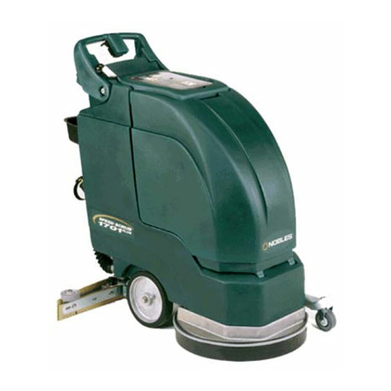
Speed Scrub
t
1701/2001/2400
Automatic Scrubber
Operator & Parts Manual
Model No.:
OSSS1701E
SS2001E
OSSS2001E
SS2001
SS2400
NOBLES INDUSTRIES
12875 RANSOM STREET
HOLLAND MI 49424
A TENNANT COMPANY
1- - 800-739- - 9359
616-786- - 2330
173126
FAX: 1- - 800- - 678- - 4240
Rev. 02 (11-97)
CUSTOMER SERVICE: 1- - 800-365-6625
Advertisement
Table of Contents


Need help?
Do you have a question about the SS2001E and is the answer not in the manual?
Questions and answers