
Subscribe to Our Youtube Channel
Related Manuals for Ferroli UM 04


Summary of Contents for Ferroli UM 04
- Page 1 FCS rem “CASSETTE” FAN COIL Mod. 04÷20 - 04-4T÷20-4T FERROLI adheres to the EUROVENT certification programme. The products concerned appear in the products guide to www.eurovent-certification.com TECHNICAL MANUAL...
- Page 2 La ditta costruttrice declina ogni responsabilità per le inesattezze contenute nel presente, se dovute ad errori di stampa o di trascrizioni. Si riserva il diritto di apportare modifiche e migliorie ai prodotti a catalogo in qualsiasi momento e senza preavviso.
-
Page 3: Table Of Contents
TABLE OF CONTENTS THIS MANUAL IS DIVIDED INTO SECTIONS. THEIR NAMES APPEAR IN THE HEADING OF EACH PAGE GENERAL SPECIFICATIONS ................. . .4 PURPOSE OF THE MACHINE . -
Page 4: General Specifications
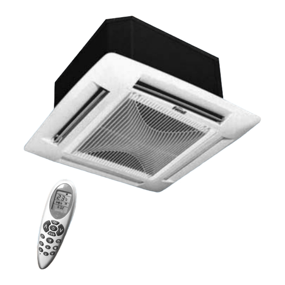
GENERAL SPECIFICATIONS The company hereby declares that the machine in question complies with the matters prescribed by the following Directives: • Machinery directive 2006/42/EC • Electromagnetic compatibility directive (EMC) 2004/108/EC • Low voltage directive (LVD) 2006/95/EC The manufacturer is associated with the EUROVENT certification program. The products are listed in the certified products guide www.eurovent-certification.com Purpose of the machine The cassette convector fan is a terminal appliance that treats the air in a room both in the summer and winter. -
Page 5: Technical Data
GENERAL SPECIFICATIONS Technical data The specifications below apply to both the base and Rem configuration MODEL 04-4T 10-4T 20-4T Version 2 Pipes 4 Pipes 1550 1900 2850 3400 3170 3900 1230 2500 4100 Cooling capacity 1800 2850 3500 4500 5100 7100 1430 3050... -
Page 6: Operation Range
OPERATION RANGE Limits to operation The main limits to operation for the machine in question are given in the following table: MODEL U.M. 04-4T 10-4T 20-4T Temperature limits (°C) Pressure limits (bar) (l/h) 1000 1600 1800 3000 1000 1400 3000 Water flow rate limits Main coil (l/h) -
Page 7: How To Select The Unit
HOW TO SELECT THE UNIT Selection criteria Example of how the unit is selected: An example of how the unit is selected has been given for explanatory purposes and to illustrate how the graphs or tables in the documentation are used. The selection will be made supposing that the unit is to be operated at the same conditions, but instal- led in two different types of system: A) system with two pipes for heating and cooling B) system with four pipes... - Page 8 HOW TO SELECT THE UNIT Selection of the model and the operating conditions in the cooling mode will therefore be as follows Model 10 Total cooling capacity 3600 [Watt] Sensible cooling effect 4000·0.72=2880 [Watt] Inlet water temperature 7[°C] Δt of the water 3.4[°C] Water flow rate 908[l/h] The loss of head can be calculated from the “WATER PRESSURE DROPS”...
- Page 9 HOW TO SELECT THE UNIT The "Cooling capacity" table for the selected model 10-4T can be used to calculate the required cooling capacity and to obtain the following: Total efficiency = 4737 [Watt] with water in the following conditions. inlet water temperature 5[°C] and a Δt of 5.4 [°C] inlet water temperature 6[°C] and a Δt of 4.35[°C] inlet water temperature 7[°C] and a Δt of 3.3 [°C] a sensible efficiency of 3700 [Watt] corresponds in both cases...
-
Page 10: General Specifications - Ir Unit For Cooling Mode Only
GENERAL SPECIFICATIONS - IR UNIT FOR COOLING MODE ONLY 2 Pipes Version Mod. 04 Cooling Capacity The tables give the performances in cooling mode at operating conditions differing from the nominal ones. The data given refer to the maximum fan speed. The ones corresponding to the medium and minimum speeds can be calculated by applying the cor- responding correction coefficients (see “Data correction factors”). -
Page 11: Mod. 08 Cooling Capacity
GENERAL SPECIFICATIONS - IR UNIT FOR COOLING MODE ONLY Mod. 08 Cooling Capacity TOTAL Cooling Capacity SENSIBLE Cooling Capacity Water W.B. Inlet air temp. D.B. Inlet air temp. Inlet temp. 3383 4520 2709 3281 3676 4060 4431 4851 2997 4129 5318 2607 3057... -
Page 12: Mod. 10 Cooling Capacity
GENERAL SPECIFICATIONS - IR UNIT FOR COOLING MODE ONLY Mod. 10 Cooling Capacity TOTAL Cooling Capacity SENSIBLE Cooling Capacity Water W.B. Inlet air temp. D.B. Inlet air temp. Inlet temp. 3975 3202 3878 4345 4798 5237 5733 3521 4852 6249 3081 3613 4132... -
Page 13: Mod. 12 Cooling Capacity
GENERAL SPECIFICATIONS - IR UNIT FOR COOLING MODE ONLY Mod. 12 Cooling Capacity TOTAL Cooling Capacity SENSIBLE Cooling Capacity Water W.B. Inlet air temp. D.B. Inlet air temp. Inlet temp. 5328 4269 5170 5793 6397 6982 7644 4720 6504 4108 4817 5510 6138... -
Page 14: Mod. 16 Cooling Capacity
GENERAL SPECIFICATIONS - IR UNIT FOR COOLING MODE ONLY Mod. 16 Cooling Capacity TOTAL Cooling Capacity SENSIBLE Cooling Capacity Water W.B. Inlet air temp. D.B. Inlet air temp. Inlet temp. 6427 8588 4195 5081 5692 6286 6862 7512 5694 7846 10105 12692 4037... -
Page 15: Mod. 20 Cooling Capacity
GENERAL SPECIFICATIONS - IR UNIT FOR COOLING MODE ONLY Mod. 20 Cooling Capacity TOTAL Cooling Capacity SENSIBLE Cooling Capacity Water W.B. Inlet air temp. D.B. Inlet air temp. Inlet temp. 8457 5870 7109 7965 8796 9601 10511 7492 10324 13296 5649 6623 7576... -
Page 16: Pipes Version
GENERAL SPECIFICATIONS - IR UNIT FOR COOLING MODE ONLY 4 Pipes Version Mod. 04-4T Cooling Capacity TOTAL Cooling Capacity SENSIBLE Cooling Capacity Water W.B. Inlet air temp. D.B. Inlet air temp. Inlet temp. 1607 2147 2717 3382 1379 1670 1871 2067 2256 2470... -
Page 17: Mod. 10-4T Cooling Capacity
GENERAL SPECIFICATIONS - IR UNIT FOR COOLING MODE ONLY Mod. 10-4T Cooling Capacity TOTAL Cooling Capacity SENSIBLE Cooling Capacity Water W.B. Inlet air temp. D.B. Inlet air temp. Inlet temp. 3383 4520 2791 3381 3788 4183 4565 4998 2997 4129 5318 2686 3149... -
Page 18: Mod. 20-4T Cooling Capacity
GENERAL SPECIFICATIONS - IR UNIT FOR COOLING MODE ONLY Mod. 20-4T Cooling Capacity TOTAL Cooling Capacity SENSIBLE Cooling Capacity Water W.B. Inlet air temp. D.B. Inlet air temp. Inlet temp. 8288 5952 7209 8076 8919 9735 10658 7343 10117 13030 5728 6716 7682... -
Page 19: General Specifications - Ip Heat Pump Unit
GENERAL SPECIFICATIONS - IP HEAT PUMP UNIT 2 Pipes Version Mod. 04 Heating Capacity Water Inlet air temp. Inlet temp. 5976 5147 4332 3525 2705 1872 5823 4989 4162 3326 2481 5651 4805 3951 3091 5445 4580 3710 2812 5219 4337 3425 6768... -
Page 20: Mod. 08 Heating Capacity
GENERAL SPECIFICATIONS - IP HEAT PUMP UNIT Mod. 08 Heating Capacity Water Inlet air temp. Inlet temp. 8211 7072 5953 4843 3716 2572 8002 6856 5718 4570 3409 7765 6603 5429 4247 7482 6294 5098 7171 5960 9300 8149 7030 5923 4817 3716... - Page 21 GENERAL SPECIFICATIONS - IP HEAT PUMP UNIT Mod. 10 Heating Capacity Water Inlet air temp. Inlet temp. 9884 8513 7166 5830 4473 3096 9631 8252 6883 5501 4103 9347 7947 6535 5112 3638 9005 7576 6137 4651 8632 7174 5665 9809 8462 7129...
-
Page 22: Mod. 12 Heating Capacity
GENERAL SPECIFICATIONS - IP HEAT PUMP UNIT Mod. 12 Heating Capacity Water Inlet air temp. Inlet temp. 12271 10569 8896 7238 5554 3844 11957 10245 8545 6830 5094 11604 9867 8114 6346 11180 9405 7619 5775 10717 8906 7033 12178 10506 8851 7198... -
Page 23: Mod. 10 Heating Capacity
GENERAL SPECIFICATIONS - IP HEAT PUMP UNIT Mod. 16 Heating Capacity Water Inlet air temp. Inlet temp. 15128 13030 10968 8923 6847 4739 14742 12631 10535 8420 6280 14307 12165 10003 7824 13784 11596 9393 13212 10980 17134 15014 12952 10912 8875 6847... -
Page 24: Mod. 20 Heating Capacity
GENERAL SPECIFICATIONS - IP HEAT PUMP UNIT Mod. 20 Heating Capacity Water Inlet air temp. Inlet temp. 20592 17735 14929 12146 9319 6450 20065 17193 14340 11461 8548 19473 16557 13615 10650 7579 18761 15783 12784 9690 17984 14946 11802 20436 17630 14853... -
Page 25: Pipes Version
GENERAL SPECIFICATIONS - IP HEAT PUMP UNIT 4 Pipes Version Mod. 04-4-T Heating Capacity Water Inlet air temp. Inlet temp. 1597 1375 1158 1556 1333 1112 1510 1284 1455 1809 1585 1367 1152 1768 1546 1326 1108 1727 1503 1279 1681 1452 1628... -
Page 26: Mod. 10-4T Heating Capacity
GENERAL SPECIFICATIONS - IP HEAT PUMP UNIT Mod. 10-4-T Heating Capacity Water Inlet air temp. Inlet temp. 3875 3337 2809 2285 1754 3776 3235 2698 2156 3664 3115 2562 3530 2970 3384 4388 3845 3317 2795 2273 1754 4289 3752 3218 2690 2156... -
Page 27: Mod. 20-4T Heating Capacity
GENERAL SPECIFICATIONS - IP HEAT PUMP UNIT Mod. 20-4-T Heating Capacity Water Inlet air temp. Inlet temp. 7564 6515 5484 4462 3423 7371 6316 5268 4210 7153 6082 5001 6892 5798 6606 8567 7507 6476 5456 4437 3423 8374 7325 6282 5251 4210... -
Page 28: Data Correction Factors
DATA CORRECTION FACTORS Data correction factors With reference to the Cooling and Heating Capacity tables, if the unit works at the same inlet water temperature and with the same water flow rate as the one for maximum speed, the efficiencies achieved at speeds differing from maximum are calcula- ted according to the following correction coefficients. - Page 29 DATA CORRECTION FACTORS 2 Pipes Unit Heating Capacity Correction Factors Model Speed Total capacity 0,68 0,79 1,00 0,48 0,82 1,00 0,61 0,73 1,00 0,54 0,72 1,00 0,40 0,68 1,00 0,39 0,72 1,00 4 Pipes Unit Heating Capacity Correction Factors Model Speed Total capacity 0,65...
-
Page 30: Water Pressure Drops
WATER PRESSURE DROPS Water Pressure Drop The following graphs give the water pressure drop valves: 2 Pipes serier water pressure drop Unit Graph size reference 1000 10000 Water flow rate [l/h] water pressure drop in the previous diagram refer to an average water temperature of 10°C 4 Pipes serier water pressure drop Main Exchanger (Cooling Mode) -
Page 31: Noise Levels
NOISE LEVELS Noise levels Sound power Level Pressure level Model Speed Central band frequency [Hz] Total 1000 2000 4000 8000 [dB(A)] [dB(A)] 04-4T 10-4T 20-4T Acoustic pressure in a 100m room with 0.5 sec. reverberation time. -
Page 32: Overall Dimension
OVERALL DIMENSION Dimensions For Installing Models 04 - 08 - 10 And 04-4T and 10-4T Ø25mm NOTE: The dimensions are given in mm. MODEL 04-4T 10-4T UNIT WEIGHT GRILLE WEIGHT Wet Connections The wet connections are fixed to the structure of the unit so as to prevent breakages when the pipes are connected. However, it is advisable to hold the union firm with a wrench. -
Page 33: Dimensions For Installing Models 12-16-20 And 20-4T
OVERALL DIMENSION Dimensions For Installing Models 12 - 16 - 20 and 20-4T Ø156 NOTE: The dimensions are given in mm. MODEL 20-4T UNIT WEIGHT GRILLE WEIGHT Wet Connections The wet connections are fixed to the structure of the unit so as to prevent breakages when the pipes are connected. However, it is advisable to hold the union firm with a wrench. -
Page 34: Installation Options
INSTALLATION OPTIONS Installation Options The side openings allow a separate outdoor air change intake duct (B) and a delivery duct to convey treated air towards an adja- cent room (A) to be made. Outdoor air change: • Remove the outer condensation-proof insulation delimited by the die-cut and take out the micro-jointed sheet metal panels using a punch. -
Page 35: Preliminary Inspections Prior To Starting
INSTALLATION OPTIONS Air delivery into an adjacent room: If air is to be blown into an adjacent room, one or more of the fins corresponding to the duct must be shut off. Apply an air intake port to the partition wall between the conditioned room in which the unit is installed and the addcent room, as shown in the figure. -
Page 36: Accessory
ACCESSORY Accessory Combinations VERSION UNIT WITH 2 PIPES UNIT WITH 4 PIPES CONFIGU- RATION ACCESSORY 04-4T 10-4T 20-4T • • • • • • CMR-F • • • • • • CONTROL TAR-F • • • TER-F • • • •... -
Page 37: Description Of Commutator (Cmr-F)
ACCESSORY Description of commutator (CMR-F) Commutator: remote control (CMR-F) 1- when in position 0, selector 0 indicates that the control is off. Turn to the sun symbol to select the heating mode or to the snow symbol to select the cooling mode. -
Page 38: Overall Dimensions Of The Control Panel
ACCESSORY Overall dimensions of the control panel 83.5 30.75 30.75 Technical specifications ELECTRICAL SPECIFICATIONS WALL-MOUNTED VERSION Power supply voltage rating 230V ± 10% Power supply frequency 50Hz Maximum power input Protection degree Less than IP40 Operating ambient temperature 0 ÷ 50°C Non-condensing environmental humidity 10 ÷... -
Page 39: Installation Options
ACCESSORY Installation options When the unit is installed, the basic and evolved commands can be configured according to the following options: • Machine type configuration: This operation, which is carried out using dip-switches, allows the type of application of the control to be selected. TYPE OF APPLICATION Basic thermostat Evolved thermostat... -
Page 40: Infrared Remote For Rem Configuration
ACCESSORY Infrared remote for Rem configuration The unit is equipped with infrared remote control with which you can set and modify all the parameters of control. The remote control (Fig. 1) has a series of keys and a display which visualizes all the activated functions and the various parameters the user and installer need in order to correctly use the unit itsel Fig. -
Page 41: Infrared Remote Dimensions
ACCESSORY Infrared remote dimensions... -
Page 42: Valve Installation
ACCESSORY Valve Installation WARNING: The valve is required not just to monitor the ambient temperature but also to shut off the chilled water that flows to the bank if the level of condensation in the tray becomes too high. It is obligatory to use this valve if the applian- ce is used for cooling purposes. -
Page 43: Valve Technical Data
ACCESSORY Valve technical data Control Element technical feature MODEL VTV 1 VTV 2 VTV 3 VTV 4 UM 230-1-50 Power supply V-F-Hz Working power input Opening time Closing time Ambient temperature max 50 °C Protection degree Valve techincal data Wet connection Water temperature 2 ÷... -
Page 44: Enabling Thermostat (Tc-F)
ACCESSORY Enabling thermostat (TC-F) This accessory can be used with the commutator control to inhibit fan operation in the heating mode if the temperature of the coil fails to reach an acceptable operating value. Tray (BCN) Made of plastic material, this collects the condensation that forms on non-insulated wet connections and the valve kit (if instal- led) during operation in the summer season, and conveys it outside (obligatory accessory for applications in the cooling mode). -
Page 45: Electrical Connections
ELECTRICAL CONNECTIONS For basic configuration Shows the electrical connections provided for the base program in conjunction with the various types of command, Commutator Control, Basic and evolved Thermostat Control. The connections that are already in the machine are indicated below. Key To Wiring Diagrams BLUE WIRE GREY WIRE... -
Page 46: Electrical Connections Of The Commutator Control
ELECTRICAL CONNECTIONS 1 - Electrical Connections of the Commutator Control Make the electric connections of the unit with Commutator Control acces- sory as shown in the following wiring diagrams. NOTE: Consult the relative "Installation Notes" for the position of the Enabling Thermostat Components (TC) and those of the Hot Ventilation Enabling Thermostat (TC-F). -
Page 47: Electrical Connections Of The Basic Thermostat Control
ELECTRICAL CONNECTIONS 2 - Electrical Connections of the Basic Thermostat Control Make the electric connections of the unit with Basic Thermostat Control accessory as shown in the following wiring diagrams. NOTE: Consult the relative "Installation Notes" for the position of the Enabling Thermostat Components (TC) and those of the Coil Probe (SB). -
Page 48: Electrical Connections Of The Evolved Thermostat Control
ELECTRICAL CONNECTIONS 3 - Electrical Connections of the Evolved Thermostat Control Make the electric connections of the unit with Evolved Thermostat Control accessory as shown in the following wiring diagrams. NOTE: Consult the relative "Installation Notes" for the position of the Enabling Thermostat Components (TC) and those of the Coil Probe (SB). -
Page 49: For Rem Configuration
ELECTRICAL CONNECTIONS For Rem configuration Shows the electrical connections provided for the Rem configuration DISPLAY BOARD 2PCB 1 2 3 4 6 7 8 J1.1 J5.1 J5.2 J5.3 J5.4 J5.5 J10.1 J10.2 J10.3 J10.4 J10.5 J10.6 J13.1 J13.2 J13.3 J2.1 J2.2 J2.3 J6A.1... - Page 50 NOTE...
- Page 51 NOTE...
Need help?
Do you have a question about the UM 04 and is the answer not in the manual?
Questions and answers