
Related Manuals for Comtrend Corporation PowerGrid 9142s


Summary of Contents for Comtrend Corporation PowerGrid 9142s
- Page 1 PowerGrid 9142s Powerline Ethernet Adapter with WiFi User Manual Version A1.0, December 23, 2014 261072-025...
- Page 2 Preface This manual provides information related to the installation and operation of this device. The individual reading this manual is presumed to have a basic understanding of telecommunications terminology and concepts. If you find the product to be inoperable or malfunctioning, please contact technical support for immediate service by email at INT-support@comtrend.com For product update, new product release, manual revision, or software upgrades,...
- Page 3 Copyright Copyright© 2014 Comtrend Corporation. All rights reserved. The information contained herein is proprietary to Comtrend Corporation. No part of this document may be translated, transcribed, reproduced, in any form, or by any means without prior written consent of Comtrend Corporation.
-
Page 4: Table Of Contents
2.2.3 Adding a New Device......................15 2.2.4 PowerGrid 9142s WiFi setup ....................16 2.2.5 WPS Setup ..........................17 2.2.6 How to use a power strip with the PowerGrid 9142s ............18 2.2.7 How to understand the STATUS LED colors ................18 2.2.8 Troubleshooting ........................19 2.2.9 Frequently Asked Questions .................... - Page 5 2.7.2 Advanced settings ........................ 42 2.7.3 Security settings ........................44 2.7.3.1 Disable Security ......................... 45 2.7.3.2 WEP ........................... 45 2.7.3.3 WPA/WPA2/WPA-Mix ....................... 46 2.7.4 Access Control ........................48 2.7.5 WPS ............................49 2.8 T ............................. 52 OOLS 2.8.1 Configuration Tools ......................52 2.8.2 Firmware Upgrade .......................
-
Page 6: Chapter 1: Product Information
Chapter 1: Product Information 1.1 WiFi Features Compatible with IEEE 802.11b/g/n wireless network standard Supports 64/128-bit WEP, WPA, and WPA2 wireless data encryption Supports MAC address filtering Supports WPS (Wi-Fi Protected Setup) Easy to use web-based GUI (Graphical User Interface) for network configuration and management purposes 1.2 Powerline Features ... -
Page 7: Safety Information
1.3 Safety Information 1. This Wireless-N Powerline Adapter is designed for indoor use only; DO NOT place this Wireless-N Powerline Adapter outdoors. 2. DO NOT put this Wireless-N Powerline Adapter at or near hot or humid places, like kitchens or bathrooms. 3. -
Page 8: Package Contents
1.5 Package contents The following items are included in your PG-9142s package: • A single PG-9142s Wireless-N Powerline Adapter • One Ethernet cable • Quick Installation Guide... -
Page 9: Chapter 2: Network Setup
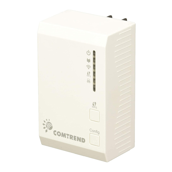
Chapter 2: Network Setup 2.1 Hardware Setup Front Panel and LED indicators Color OFF: No power (perhaps the socket to which the Wireless-N Powerline Adapter is connected does not work or is disabled) Power Green: Wireless-N Powerline Adapter is plugged in with voltage present Blink: Establishing connection Green: Excellent network traffic (i.e. -
Page 10: Bottom Panel
Green: WiFi connection established WLAN Blink: Data transmitting or receiving over WLAN (secured network) OFF: WiFi disabled Blink: WPS mode is on for 120 seconds OFF: WPS mode is off ETHERNET Green: LAN connection established OFF: LAN connection is not established Blink: Data transmitting/receiving Bottom Panel Item Name... - Page 11 Front Panel Buttons Item Name Description Press more than 2 seconds to start WPS connection Press for between 2 – 11 seconds to join/establish a powerline Config network Press for over 11 seconds to leave a powerline network...
-
Page 12: Powerline Logical Network
These steps show how to connect a PowerGrid 9141s unit to a modem or router. This guide assumes that a PowerGrid 9141s will be the primary connection to the modem / router and the PowerGrid 9142s will be used within the network to connect to WiFi capable devices (E.g. Tablet, IP Phone, Access Point). -
Page 13: Initial Setup
2.2.1 Initial Setup 1. Ensure that your modem or router is powered on. 2. Plug a PowerGrid 9141s unit into the power socket closest to the modem/ router. The Power LED will blink GREEN. 3. Connect the PowerGrid 9141s unit to the LAN port of the modem/router with an Ethernet (RJ-45) cable. -
Page 14: Device Connection
2.2.2 Device Connection These steps show how to connect a PowerGrid 9142s to a network device. Below we use an Ethernet camera as a network device. 1. Plug a PowerGrid 9142s unit into the power socket closest to the camera or other device. The Power LED on the PowerGrid 9142s should light up GREEN. -
Page 15: Adding A New Device
2.2.3 Adding a New Device Follow steps 1-4 in section 2.2.2 to add additional PowerGrid 9142s devices to the network. Press the “Config” button on the new device and one other PowerGrid device in the network so they can pair and transmit data successfully. -
Page 16: Powergrid 9142S Wifi Setup
- and select - the SSID that is located on your PowerGrid 9142s device label. 2. When prompted, input the WiFi key located on the PowerGrid 9142s device label to connect. 3. You should now be successfully connected to the PowerGrid 9142s WiFi network. -
Page 17: Wps Setup
Setup) then you can use this method to set up your PowerGrid 9142s‟ Wi-Fi network. 1. Press and hold the WPS button for more than 2 seconds on the PowerGrid 9142s to activate its WPS. The PowerGrid 9142s‟ WPS LED should flash to indicate a WPS connection is in progress. -
Page 18: How To Use A Power Strip With The Powergrid 9142S
2.2.6 How to use a power strip with the PowerGrid 9142s If you must plug your Wireless-N Powerline Adapter into a power strip, we suggest you use a basic power strip as the more advanced ones have a filter that can interfere with the Powerline signal. -
Page 19: Troubleshooting
1) POWER LED is OFF: If the POWER LED goes off, please make sure that your power socket is working properly (perhaps by testing with another device).Then plug in your PowerGrid 9142s again. If the POWER LED does not light up, please contact your equipment supplier for further information. -
Page 20: Frequently Asked Questions
2.2.9 Frequently Asked Questions This PG-9142s Wireless-N Powerline Adapter has been designed to be reliable and easy to use in creating or extending your existing home network. However, should you experience any problems, please refer to the list below to aid in troubleshooting. - Page 21 3. Why is SDTV video not streaming? Check the STATUS indicator LED in the adapter connected to the STB. If the indicator is RED this means that the PLC link is not able to play an SDTV streaming. ...
- Page 22 What if my Powerline Adapters don’t fit into the plug socket? Your Wireless-N Powerline Adapter might not fit because the sockets are too close to the floor or are in the skirting board. The easiest way around this is to use a trailing power strip, and plug the Adapter into the strip.
-
Page 23: Connecting To Pg-9142S Wireless-N Powerline Adapter By Web Browser
2.3 Connecting to PG-9142s Wireless-N Powerline Adapter by web browser After the network connection is complete, the next step you should do is setup the Wireless-N Powerline Adapter with proper network parameters, so it can work properly in your network environment. Before you can connect to the Wireless-N Powerline Adapter and start configuration procedures, your computer must be able to get an IP address automatically (use dynamic IP address). -
Page 24: Windows 7 Ip Address Setup
2.3.1 Windows 7 IP address setup 1. Click the Start button and select Control Panel. Double click Network and Internet and click Network and Sharing Center, the Network and Sharing Center window will appear. 2. Click Change adapter settings and right click on the Local Area Connection icon and select Properties. -
Page 25: Connecting To Web Management Interface
2.3.2 Connecting to Web Management Interface All functions and settings of this Wireless-N Powerline Adapter must be configured via web management interface. Please start your web browser, and input „192.168.0.10’ in address bar, then press „Enter‟ key. The following message should be shown: Please input user name and password in the field respectively, default user name is „root‟, and default password is „12345‟, then press „OK‟... -
Page 26: Quick Setup
2.4 Quick Setup After login, the Quick Setup screen will appear. It is the default screen when no connections exist. This screen allows for the configuration of DSL settings and the IP configuration. It includes LAN, Wireless and Security setup screens. NOTE: If you can’t see the web management interface, and you’re being prompted to input user name and password again, it means you didn’t input username and password correctly. -
Page 27: Wireless Settings
Input the IP address of the domain name server. DHCP Disable or Enable DHCP client. If Enabled, IP Address, Subnet Mask, Default Gateway and DNS will be got by DHCP client automatically. Click the Next button to continue. 2.4.2 Wireless Settings This page is used to configure the parameters for the wireless connection of tablets, smart phones, and laptops. - Page 28 Mode PG-9142s only supports AP mode. Network In Infrastructure Mode, wireless clients can access the other Type networks (perhaps Internet) via this AP. For AP. Only Infrastructure Mode is allowed here. SSID Input the ESSID (the name used to identify this Wireless-N Powerline Adapter) here.
-
Page 29: Security Settings
2.4.3 Security Settings Turn on WEP or WPA encryption to prevent unauthorized access to your wireless network. Select the Encryption method from the drop down menu. Then select and fill in the required parameters. Click the Apply button to display the following. Do not turn off or reboot the device during this time. -
Page 30: Status
2.5 Status 2.5.1 Device Status This page shows the current status and some basic settings of the device. Up time Displays the total time passed since the Wireless-N Powerline Adapter was powered on. Firmware Version Displays Firmware version of wireless Wireless-N Powerline Adapter. - Page 31 Associated Clients Displays the number of connected wireless clients. Attain IP Protocol Displays the method of obtaining the IP address. IP Address Displays the IP address of this Wireless-N Powerline Adapter. Subnet Mask Displays the net mask of IP address. Default Gateway Displays the IP address of default gateway.
-
Page 32: System Log
2.5.2 System Log This page shows the system's operational information; start up time, system events, and also lets you enable or disable certain logging features. To enable the System Log tick the check box and make your selections. Click the Apply Changes button to display the following. Click the Reboot Now button for the changes to take effect. -
Page 33: Statistics
2.5.3 Statistics This page shows the packet count for the Wireless and Ethernet LAN. Wireless LAN It shows the statistic count of sent packets on the Sent Packets wireless LAN interface Wireless LAN It shows the statistic count of received packets on the Received Packets wireless LAN interface Ethernet LAN... -
Page 34: General Setup
2.6 General Setup 2.6.1 Time Zone Setting Automatically synchronize your Wireless-N Powerline Adapter time with Internet time servers. Select your local time zone from the drop-down menu. This page is used to configure NTP client to get current time. After click „Time Zone‟ on the left of web management interface and the following messages will be displayed: Time Zone Select Click the time zone in your country... -
Page 35: Password
2.6.2 Password This page is used to set the account to access the web server of your Wireless-N Powerline Adapter. Emptying the user name and password fields will disable the protection. Click the Apply Changes button to create the new password setting. Click the Reset button to reset/clear the data just input on screen. -
Page 36: Tr-069 Client
2.6.3 TR-069 Client WAN Management Protocol (TR-069) allows an Auto-Configuration Server (ACS) to perform auto-configuration, provision, collection, and diagnostics of this device. Select desired values and click Apply Changes to configure TR-069 client options. ACS URL URL for the CPE to connect to the ACS using the CPE WAN Management Protocol. - Page 37 ACS User Name Username used to authenticate the CPE when making a connection to the ACS using the CPE WAN Management Protocol. This username is used only for HTTP-based authentication of the CPE. ACS Password Password used to authenticate the CPE when making a connection to the ACS using the CPE WAN Management Protocol.
-
Page 38: Lan Settings
2.6.4 LAN Settings Enable your Wireless-N Powerline Adapter to dynamically receive an IP Address from your home gateway. Your Wireless-N Powerline Adapter must have an IP Address in the Local Area Network's existing IP range. IP Address The IP address for the Wireless-N Powerline Adapter Subnet Mask The Subnet Mask for the Wireless-N Powerline Adapter Default Gateway... -
Page 39: Wireless
2.7 Wireless 2.7.1 Basic settings This page is used to configure the parameters for the wireless connection of tablets, smart phones, and laptops. Disable Wireless Click it will disable your Wireless LAN Interface. The LAN interface Wireless Interface default is Enable. Band Please select the wireless band you wish to use. - Page 40 If you select 2.4GHz (B+G), then only wireless clients using 802.11b and 802.11g band will be able to connect to this Wireless-N Powerline Adapter. If you want to allow 802.11b, 802.11g, and 802.11 Draft-N clients to connect to this Wireless-N Powerline Adapter, select 2.4GHz (B+G+N).
- Page 41 When you enable WMM function, the Wireless-N Powerline Adapter will define the priority of different kinds of data, to give higher priority to applications which require instant responding. Therefore you can improve the performance of such network applications. Data rate Set the wireless data transfer rate to a certain value.
-
Page 42: Advanced Settings
2.7.2 Advanced settings This Wireless-N Powerline Adapter has many advanced wireless features. Please note that all settings listed here are for experienced users only, if you‟re not sure about the meaning and function of these settings, please don‟t modify them, or the wireless performance will be reduced. - Page 43 Preamble Type Set the type of preamble of wireless radio, Do not modify default value if you don’t know what it is, default setting is ‘Short Preamble’ IAPP Click to enable or disable the IAPP function. Protection Click to enable or disable the Protection function. Aggregation Click to enable or disable the Aggregation function.
-
Page 44: Security Settings
2.7.3 Security settings This Wireless-N Powerline Adapter provides many types of wireless security (wireless data encryption). When you use data encryption, data transferred by radio signals in the air will become unreadable for those people who don‟t know correct encryption key (encryption password). You can click „Security‟... -
Page 45: Disable Security
2.7.3.1 Disable Security When you select „Disable‟, wireless encryption for the network is disabled. 2.7.3.2 WEP WEP (Wired Equivalent Privacy) is a common encryption mode, it‟s safe enough for home and personal use. But if you need higher level of security, please consider using WPA encryption (see next Section). -
Page 46: Wpa/Wpa2/Wpa-Mix
802.1x While Encryption is selected to be Open and WEP. Authentication Click the check box to enable IEEE 802.1x authentication function. Key Length There are two types of WEP key length: 64-bit and 128-bit. Using „128-bit‟ is safer than ‟64-bit‟, but will reduce some data transfer performance. - Page 47 WPA Authentication While Encryption is selected to be WPA. Mode Click to select the WPA Authentication Mode with Enterprise (RADIUS) or Personal (Pre-Shared Key). Cipher Suite There are two type of Cipher :TKIP and AES Pre-shared Key Please select the format of pre-shared key here, available Format options are „Passphrase‟...
-
Page 48: Access Control
2.7.4 Access Control Another security measure you can use to keep hackers and intruders away is „Access Control‟. You can pre-define a so-called „white-list‟, which contains MAC addresses of the wireless clients you trust. All other wireless client with the MAC address which is not in your list will be denied by this Wireless-N Powerline Adapter. -
Page 49: Wps
2.7.5 WPS Wi-Fi Protected Setup (WPS) is the simplest way to build connection between wireless network clients and this Wireless-N Powerline Adapter. You don‟t have to select encryption mode and input a long encryption passphrase every time when you need to setup a wireless client, you only have to press a button on wireless client and this Wireless-N Powerline Adapter, and the WPS will do the setup for you. - Page 50 Disable WPS Check this box to enable or disable WPS function WPS Status Displays WPS status. If data encryption settings of this Wireless-N Powerline Adapter has never been set, „unConfigured‟ message will be displayed her.; if data encryption settings has been set before, „Configured‟ message will be displayed here.
- Page 51 STOP WSC Click „Stop WSC‟ to stop WPS setup procedure. Client PIN Number Please input the PIN code of the wireless client you via client wish to connect, and click „Start PIN‟ button. The „WLAN‟ LED on the Wireless-N Powerline Adapter will be steady on when this Wireless-N Powerline Adapter is waiting for incoming WPS request.
-
Page 52: Tools
2.8 Tools 2.8.1 Configuration Tools Use the "Backup" tool to save the current configuration of your Wireless-N Powerline Adapter to a file named "config.dat". You can then use the "Restore" tool to recover the saved configuration to your Wireless-N Powerline Adapter. Click the Backup button to display the following. -
Page 53: Firmware Upgrade
2.8.2 Firmware Upgrade This page allows you upgrade the Wireless-N Powerline Adapter firmware to new version. Please note, do not power off the device during the upload because it may crash the system. After click „ Upgrade Firmware‟ on the left of web management interface and the following messages will be displayed: Click the Browse button to locate the file. -
Page 54: Factory Defaults
2.8.3 Factory Defaults This page allows you to reset the current configuration to factory defaults. Click the Apply button to reset the configuration. -
Page 55: Save/Reload Setting
2.8.4 Save/Reload setting This page allows you save current settings to a file or reload the settings from the file that was saved previously. Besides, you could reset the current configuration to factory default. After click „Save/Reload setting‟ on the left of web management interface and the following messages will be displayed:... -
Page 56: Chapter 3: Homeplug Av User Application Tool
Chapter 3: HomePlug AV User Application Tool This section provides the installation instructions for the HomePlug AV User Application Tool. This utility is meant to be used in the home by the end user for viewing and configuring the CG2x10 home network. The following are the main features of this application: ... - Page 57 Should the above windows pop up, please go to Comtrend‟s North American Website to download the relevant software. When the following window displays click the Next button. Select the destination folder:...
- Page 58 Select the Start Menu folder and then press Install: Press Finish: If you don‟t have Microsoft .NET Framework 4 installed on your PC, the following window will appear:...
- Page 59 Click on the “Install” button to run the Microsoft .NET Framework 4 installation (from the web).
-
Page 60: User Guide
3.2 User Guide 3.2.1 Configuration When you open the application, you will be asked to select the network card that is connected to your CG2x10 HPAV device: Select the network card from the drop-down list. NOTE: The PC NIC must have a fixed IP, either a static one or one that is given by a DHCP server (like a home router). -
Page 61: Network Topology
3.3 Network Topology 3.3.1 Topology Information In the network topology tab, a graphic representation of all devices connected to your local CG2x10 HPAV device will be shown. In the example below, there are no CG2x10 devices connected to your PC: The example below shows one CG2x10 HPAV device connected to your PC. - Page 62 The example below shows two CG2x10 HPAV devices connected to the network. The name of the local device on the left is “Room1,” and the name of the remote device on the right is “Room2.”...
-
Page 63: Device Details
3.3.2 Device Details The MAC address and other information relevant to a device (e.g. firmware version, manufacturer name) can be seen by placing the mouse cursor over one of the devices of interest listed on the screen. For example, placing the mouse over device “Room1”... -
Page 64: Connectivity Information On The Entire Network
3.3.3 Connectivity Information on the Entire Network In order to get the current PHY rate for the entire network, you need to run traffic between the two CG2x10 HPAV devices. (Any program that sends bi-directional data between the two hosts connected to the “Room1” and “Room2” devices will be good enough.) After running some traffic, you should immediately receive information about the quality of the connection. -
Page 65: Connectivity Information For A Specific Device
3.3.4 Connectivity Information for a Specific Device “Room 1” CG2x10 device “Room 2” CG2x10 device “Room 3” CG2x10 device “Room 4“ Foreign (non-CG2x10) device... - Page 66 If you click on a specific device, you will get the connectivity quality towards that device from each of the other devices in the network. Clicking on Output Graph Explanation “Room 1” “Room 2” connectivity towards “Room 1” is (left) excellent “Room 3”...
-
Page 67: Average Network Phy Rate
3.3.5 Average Network PHY Rate The average network PHY rate is shown in the center of the network topology screen. For the case shown in the previous table, the average rate is 110Mbps (excellent average connectivity among all devices). -
Page 68: Network Topology Legend
3.3.6 Network Topology Legend Connectivity legend: Excellent > 80 Mbps Good 50 – 80 Mbps Poor < 50 Mbps Not connected no traffic ICON Legend: The local drive is indicated with a picture of a PC connected to it. A CG2x10 HPAV device is represented by the black plug icon. -
Page 69: Change Device Id
3.4 Change Device ID A free-text unique name can be given to each HPAV device. To do so, choose the “Change Device ID” tab, select the device from the MAC-Address drop-down list, enter the new device name, and press on the “Change Device ID” button. In the example below, the user selected the MAC (00:c5:d9:00:40:47) named “Room1”... - Page 70 In this example, we click on the “Room 1” name: And enter a new device name in the white rectangle:...
-
Page 71: Update Firmware
3.5 Update Firmware It is possible to update the firmware of a working device to a new firmware version. This is currently supported for local devices only. You are required to supply the bin file via the “Browse” button found in the Upgrade Firmware tab. The following steps are required to update the firmware on a device: 1. - Page 72 2. Press on the “Upgrade Firmware” button. 3. Confirm the update message (Click on Yes).
- Page 73 4. Wait until the upgrade process is finished. 5. Once the process is completed, the following message will be displayed:...
-
Page 74: Configuration Wizard
3.6 Configuration Wizard This wizard enables you to create a new private network and to add remote devices to that network. The following process can be used to create a private network and add remote devices to that network:... -
Page 75: First Step - Creating A New Private Network
3.6.1 First Step – Creating a New Private Network Press the “Launch Wizard” button. Check the “Change Password” box and enter a Network Password. You may enter any string of characters (up to 64 characters). In the example below, “FooPassword1234” was used as the password. Click on “Change”... -
Page 76: Second Step - Adding Remote Devices To The New Private Network
3.6.2 Second Step – Adding Remote Devices to the New Private Network For each remote device that is added to the private network, you must enter the Device Password found on the remote device's label. Use the screen below to enter this information. - Page 77 In case of a failure, you will receive the following failure notification: In case of success: 1. You will receive the following success notification: 2. You should also see the details of the other device that you have just added to your network.
- Page 78 3. The network topology, before adding the remote password “AAAA-BBBB-CCCC-DDDD”, was: The network topology, after adding the remote device, is: If you have more devices to add, you can add them by entering their device password and by clicking again on the “Add Device” button.
-
Page 79: Language
3.7 Language It is possible to dynamically change the UA language between English and Chinese (traditional). -
Page 80: Troubleshooting
3.8 Troubleshooting Error Message: Explanation: The application failed to read the network topology information from the local device. Please check your IP settings and check your cables. Another CG2x10 application is open and communicating with the device. Please close any other tool you might have running on your PC. -
Page 81: Appendix A: Specifications
Appendix A: Specifications Interface RJ-45 x 1 for Ethernet connection Internal WiFi Antenna x 2 AC power plug x1 PLC paring button x1 Reset button x1 WPS button x1 Ethernet 10/100 Mbps BaseT auto-sense ...
Need help?
Do you have a question about the PowerGrid 9142s and is the answer not in the manual?
Questions and answers