
Subscribe to Our Youtube Channel
Related Manuals for Comtrend Corporation PowerGrid-9171n


Summary of Contents for Comtrend Corporation PowerGrid-9171n
- Page 1 PowerGrid-9171n Powerline Ethernet Adapter User Manual Version A2.0, August 25, 2015 261072-029...
- Page 2 Copyright Copyright©2014 Comtrend Corporation. All rights reserved. The information contained herein is proprietary to Comtrend Corporation. No part of this document may be translated, transcribed, reproduced, in any form, or by any means without prior written consent of Comtrend Corporation.
- Page 3 Protect Our Environment This symbol indicates that when the equipment has reached the end of its useful life, it must be taken to a recycling centre and processed separate from domestic waste. The cardboard box, the plastic contained in the packaging, and the parts that make up this PLC can be recycled in accordance with regionally established regulations.
-
Page 4: Table Of Contents
Table of Contents Chapter 1 Product Information..........................6 1.1 Front Panel and LED indicators ........................6 1.2 Bottom Panel ............................... 7 1.3 How to understand the COVERAGE LED colors ................... 8 1.4 Point-to-Point Network ..........................9 1.5 Point to Multipoint Network ........................10 Chapter 2 Log In Procedure .......................... - Page 5 17.2 Statistics ..............................48 17.3 Time Zone Setting ............................ 49 17.4 Upgrade Firmware ........................... 50 17.5 Save/Reload Settings ..........................51 17.6 TR-069 Configuration ..........................52 17.7 Password Setup ............................54 Chapter 18 Logout ............................... 55...
-
Page 6: Chapter 1 Product Information
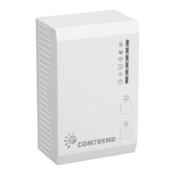
Chapter 1 Product Information 1.1 Front Panel and LED indicators WPS Button: Press for 2 – 10 seconds to start the WPS function. Press for over 10 seconds to reset to factory defaults. Power Button: Push once to power up the PG-9171n Push once to power down the PG-9171n COLOR MODE... -
Page 7: Bottom Panel
LAN connection established Ethernet LAN connection is not established Green Blink Data transmitting/receiving Power The device is powered up Green The device is powered down 1.2 Bottom Panel Item Name Description Press more than 2 seconds (“Security” LED starts slow blinking) and released: the “One Button Security Setup”... -
Page 8: How To Understand The Coverage Led Colors
1.3 How to understand the COVERAGE LED colors The COVERAGE LED displays quality of the network and provides important information that will provide solutions to common questions, such as why a High Definition (HD) movie is not showing or shows with pixels. -
Page 9: Point-To-Point Network
1.4 Point-to-Point Network CASE 1: Estimated throughput is less than 20 Mbps. The PLC channel is not able to transmit an SDTV channel. The COVERAGE LED will be RED as shown in the following figure: CASE 2: Estimated throughput is greater than 20 Mbps but less than 40 Mbps. The PLC channel is able to transmit an SDTV channel, but not two SDTV channels simultaneously or one HDTV channel. -
Page 10: Point To Multipoint Network
1.5 Point to Multipoint Network In the case where the PLC network is composed of three or more adapters, similar situations could arise as with a point-to-point network. CASE 1: The COVERAGE LED in G.hn adapter 2 and G.hn adapter 3 will show the estimated level of the ... -
Page 11: Chapter 2 Log In Procedure
Chapter 2 Log In Procedure 2.1 Configure STATIC IP MODE In static IP mode, you assign IP settings to your PC manually. Follow these steps to configure your PC IP address to use subnet 10.10.1.x. NOTE: The following procedure assumes you are running Windows XP. However, the general steps involved are similar for most operating systems (OS). -
Page 12: Logging In
2.2 Logging In Perform the following steps to login to the web user interface. STEP 1: Start the Internet browser and enter the default IP address for the device in the Web address field. For example, if the default IP address is 10.10.1.69, type http://10.10.1.69 STEP 2: A dialog box will appear, such as the one below. -
Page 13: Chapter 3 G.hn Interface
Chapter 3 G.hn Interface 3.1 Basic Configuration Domain Name string of all nodes in the network. Force node Type force the modem to have a particular role (END POINT or DOMAIN MASTER) G.hn profile of all nodes in the network: selecting which G.hn profile must be applied to the network (PLC 50MHz, PLC 50MHz with MIMO, PLC 100MHz, COAX 100MHz and PHONE 100MHz). -
Page 14: Ndim Configuration
3.2 NDIM Configuration NDIM mode set to Automatic for enabling automatic DOD selection functionality and set to Manual for manual configuration of DOD. Domain ID (DOD) manually set the DOD number from 1 to 15 to use a different preamble seed than the default 0. -
Page 15: Chapter 4 Ip Interface
Chapter 4 IP Interface 4.1 IP config In the IP configuration tab of one G.hn node, the IPv4 and IPv6 settings can be read and changed. IPv4 subsection: DHCPv4 enabled: in the case of choosing "No" (i.e fixed) IP configuration in the previous option, the IPv4 Address, Subnet Mask, Default Gateway and DNS IPv4 Address should be configured;... -
Page 16: Chapter 5 Ethernet Interface
Chapter 5 Ethernet Interface The Ethernet table shows the coverage & Info of the Ethernet interface; including Interface, Speed, Duplex, Interface Type, Mode, Internal PHY & Link. Powersaving Ethernet powersaving can be disabled, enabled by Ethernet link or enabled by Ethernet activity; idle timer can be configured as well. -
Page 17: Chapter 6 Device Interface
Chapter 6 Device Interface 6.1 HW information In this tab, basic information such as MAC Address, Serial Number, HW Product and Revision, ASIC and Chipset of the selected node is shown. Other information about the Ethernet port is also shown. -
Page 18: Sw Information
6.2 SW information Shows the FW version and system uptime. Configuration password The nodes in the network: to change the configuration password string from the default ("paterna") to another; decided by the user. Software update: Current loaded firmware and API version are shown. SW can be upgraded via FTP or TFTP. L2 is proprietary and is reserved for future use. -
Page 19: Chapter 7 Multicast Interface
Chapter 7 Multicast Interface 7.1 MCAST Configuration In the MCAST Configuration tab of "My Network", IGMP snooping and MLD features can be enabled or disabled. Also, IGMP multicast IP addresses ranges which the G.hn PLC network will sniff; can be configured. ... -
Page 20: Chapter 8 Qos Menu
Chapter 8 QoS menu 8.1 QoS Configuration In the QoS configuration tab, the packet classifier can be managed to define a QoS rule for incoming Ethernet traffic, and assign a priority to be used in the G.hn network. Press the “Update" button for loading the newly configured settings: ... - Page 21 Example 1 If QoS criterion: 802.1p, all other options are grayed out, and follow the QoS rules below. According to G.9960 specs, the priority mapping recommended by [IEEE 802.1D] subclause 7.7.3 is presented in Table III.1. for four priority queues. Priority Acronym Traffic Types...
- Page 22 Note: If the user selects “Custom” as the QoS criterion, there will be an inaccuracy after the user clicks the OK button at the bottom of the screen (i.e the Offset value will increase by two (from 7-9 in the rule 1-8 boxes).
-
Page 23: Chapter 9 Vlan Interface
Chapter 9 VLAN Interface 9.1 VLAN Configuration In the VLAN Configuration tab of one G.hn node, a VLAN tag can be added or removed per interface. Also, removing a tag at egress per interface can be also enabled or disabled: ... -
Page 24: Chapter 10 G.hn Spectrum Interface
Chapter 10 G.hn spectrum Interface 10.1 Notches In this tab a table with all configured Notches of selected node will be shown. The table is composed of next columns for every notch: Notch Number, Type of notch, Start Frequency (KHz), Stop Frequency (KHz), Depth (in dB) and Enabled. -
Page 25: Chapter 11 Log File Interface
Chapter 11 Log file Interface 11.1 Log File In the Log File configuration tab the following settings can be read, and changed by clicking on the corresponding "Update" button for the selected node: Enable Log File set to YES for enabling Log File functionality in the node and set to NO for disabling ... -
Page 26: Chapter 12 Advanced Interface
Chapter 12 Advanced Interface Broadcast suppression In this tab the broadcast suppression feature can be managed. Broadcast traffic higher than the selected value will be dropped. Hardware Reset: Click on this button to perform a reboot in the node. Factory reset: Click the OK button to order a factory reset of the node. -
Page 27: Chapter 13 Wifi Log In Procedure
Chapter 13 WiFi Log In Procedure 13.1 Configure STATIC IP MODE In static IP mode, you assign IP settings to your PC manually. Follow these steps to configure your PC IP address to use subnet 192.168.0.x. NOTE: The following procedure assumes you are running Windows XP. However, the general steps involved are similar for most operating systems (OS). -
Page 28: Logging In
13.2 Logging In Perform the following steps to login to the web user interface. STEP 1: Start the Internet browser and enter the default IP address for the device in the Web address field. For example, if the default IP address is 192.168.0.9, type http://192.168.0.9 STEP 2: A dialog box will appear, such as the one below. -
Page 30: Chapter 14 Wireless
Chapter 14 Wireless 14.1 Basic Settings This page is used to configure the parameters for wireless LAN clients which may connect to your Access Point. Here you may change wireless encryption settings as well as wireless network parameters. Disable Wireless LAN Interface: Select the check box to disable the wireless LAN interface. - Page 31 Field Description Band Select the wireless band you wish to use. By selecting different band setting, you’ll be able to allow or deny the wireless client of a certain band. If you select 2.4GHz (B), 2.4GHz (N), or 2.4GHz (G), only wireless clients using the wireless band you select (802.11b, 802.11 n, or 802.11g) will be able to connect to this access point.
-
Page 33: Advanced Settings
14.2 Advanced Settings These settings are only for more technically advanced users who have sufficient knowledge about wireless LAN. These settings should not be changed unless you know what effect the changes will have on your Access Point. Field Description Fragment Threshold Set the Fragment threshold of wireless radio. - Page 34 Field Description Protection Click to enable or disable the Protection function. Aggregation Click to enable or disable the Aggregation function. Short GI Click to enable or disable the Short GI function. STBC Click to enable or disable the STBC function. LDPC Click to enable or disable the LDPC function.
-
Page 35: Security
14.3 Security This page allows you setup the wireless security. Turning on WEP or WPA by using Encryption Keys could prevent any unauthorized access to your wireless network. Select SSID: Select which SSID’s security settings to configure. Encryption: Select an encryption type from the drop down menu (and refer to the appropriate section below for more details). - Page 36 14.3.1 802.1x Authentication If you select “Disabled” or “WEP” as your encryption type, you can check the “Enable 802.1x Authentication” box to enable 802.1x authentication based on a RADIUS user authentication server. RADIUS Server IP Input the IP address of the RADIUS authentication server here. Address RADIUS Server Port Input the port number of the RADIUS authentication server here.
- Page 37 14.3.2 WEP (Shared Key) Wired Equivalent Privacy (WEP) is a basic encryption type. WPA encryption is recommended – though some legacy wireless devices may only support WEP. WEP supports data rates up to a maximum 54Mbps. Enable 802.1x Authentication Check this box to enable 802.1x user authentication. Authentication You can select Open System or Shared Key or Auto for your authentication method.
- Page 38 Your changes have been saved. The router must be rebooted for the changes to take effect. You can reboot now, or you can continue to make other changes and reboot later. 14.3.3 WPA2 or WPA Mixed+Personal (Pre-Shared Key) WPA pre-shared key is the recommended and most secure encryption type. Authentication Mode Select Personal (Pre-Shared Key).
- Page 39 Pre-shared Key Please enter the key according to the key format you selected above. For security reasons, it’s best to use a complex, hard-to-guess key. TKIP supports a maximum data rate of 54Mbps. Click the Apply Changes button to display the following. Your changes have been saved.
- Page 40 14.3.4 WPA2 or WPA Mixed+Enterprise (Radius) WPA RADIUS is a combination of WPA encryption and RADIUS user authentication. If you have a RADIUS authentication server, you can authenticate the identity of every wireless client against a user database. Authentication Mode Select Enterprise (RADIUS).
- Page 41 Your changes have been saved. The router must be rebooted for the changes to take effect. You can reboot now, or you can continue to make other changes and reboot later.
-
Page 42: Access Control
14.4 Access Control If you choose 'Allowed Listed', only those clients whose wireless MAC addresses are in the access control list will be able to connect to your Access Point. When 'Deny Listed' is selected, these wireless clients on the list will not be able to connect the Access Point. -
Page 43: Wireless Site Survey
14.5 Wireless Site Survey This page provides tool to scan the wireless network. If any Access Point or IBSS is found, you could choose to connect it manually when client mode is enabled. Click on the Site Survey to display the following. SSID: The SSID that the wireless client connected to. -
Page 44: Wifi Protected Setup
14.6 WiFi Protected Setup This page allows you to change the setting for WPS (Wi-Fi Protected Setup). Using this feature could let your wireless client automically syncronize its setting and connect to the Access Point in a minute without any hassle. -
Page 45: Chapter 15 Tcp/Ip Settings
Chapter 15 TCP/IP Settings 15.1 LAN Interface This page is used to configure the parameters for local area network which connects to the LAN port of your Access Point. Here you may change the setting for IP address, subnet mask, DHCP, etc.. IP Address: Specify an IP address here. -
Page 46: Chapter 16 Ipv6
Chapter 16 IPv6 16.1 IPv6 LAN Setting This page is used to configure the parameters for IPv6 in the local area network. Click the Enable IPv6 checkbox if you want to enable IPv6 addressing in the LAN of your extender. By default, IPv6 is disabled. -
Page 47: Chapter 17 Management
Chapter 17 Management 17.1 Status This page shows the current status and some basic settings of the device. -
Page 48: Statistics
17.2 Statistics This page shows the packet counters for transmission and reception regarding to wireless and Ethernet networks. Click the Refresh button to get the latest statistics. -
Page 49: Time Zone Setting
17.3 Time Zone Setting You can maintain the system time by synchronizing with a public time server over the Internet. Time Zone Select: Choose your preferred time zone. Automatically Adjust Daylight Saving: Tick the box if appropriate for your region. Enable NTP client update: Enable the NTP function here (date and time can be synchronized with a time server). -
Page 50: Upgrade Firmware
17.4 Upgrade Firmware This page allows you upgrade the Access Point firmware to new version. Please note, do not power off the device during the upload because it may crash the system. STEP 1: Obtain an updated software image file from your ISP. STEP 2: Enter the path and filename of the firmware image file in the Select File field or click the Browse button to locate the image file. -
Page 51: Save/Reload Settings
17.5 Save/Reload Settings This page allows you save current settings to a file or reload the settings from the file which was saved previously. Besides, you could reset the current configuration to factory default. Click the Save button to save current settings to PC. Click the Browse button to locate the desired file. -
Page 52: Tr-069 Configuration
17.6 TR-069 Configuration This page is used to configure the TR-069 protocol settings, including the settings for the ACS’s parameters. This page is used to configure the TR-069. Here you may change the setting for the ACS's parameters. - Page 53 Option Description Enable TR-069 Tick the radio button to enable. Enabled by default. URL for the CPE to connect to the ACS using the CPE WAN Management Protocol. This parameter MUST be in the form of a valid HTTP or HTTPS URL. An HTTPS URL indicates that the ACS supports SSL.
-
Page 54: Password Setup
17.7 Password Setup This page is used to set the account to access the web server of Access Point. Empty user name and password will disable the protection. Input the User Name. Then input the New Password and Confirm the New Password. Click the Apply Changes button to save the new password. -
Page 55: Chapter 18 Logout
Chapter 18 Logout This page is used to logout from PG-9171n. Click the Apply Change button to logout from the PG-9171n.
Need help?
Do you have a question about the PowerGrid-9171n and is the answer not in the manual?
Questions and answers