Table of Contents
Advertisement
Document Type: Service Manual
Version: V1.0 041318
SERVICE MANUAL
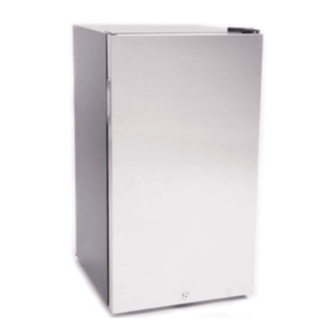
BR1000SS
BWC120SLD
EdgeStar Refrigerator for
EdgeStar 113 Can Beverage
Kegerator Conversion
Center Stainless Door
*Beer refrigerator for KC1000SS Kegerator Kit
EdgeStar, 8606 Wall St, Suite 1800, Austin, TX 78754
support.edgestar.com • service@edgestar.com • edgestar.com
*Warranty service should be performed by an authorized service representative only.
Advertisement
Table of Contents

Related Manuals for EdgeStar BR1000SS


Summary of Contents for EdgeStar BR1000SS
- Page 1 EdgeStar 113 Can Beverage Kegerator Conversion Center Stainless Door *Beer refrigerator for KC1000SS Kegerator Kit EdgeStar, 8606 Wall St, Suite 1800, Austin, TX 78754 support.edgestar.com • service@edgestar.com • edgestar.com *Warranty service should be performed by an authorized service representative only.
-
Page 2: Table Of Contents
CONTENTS CONTENTS ............................1 SAFETY PRECAUTIONS ........................2 ELECTRICAL SAFETY ........................3 GENERAL SAFETY ......................... 4 1.2 SAFETY INSTRUCTIONS FOR REFRIGERANT ................5 2. DESCRIPTION OF PRODUCT FEATURES ..................5 3. INSTALLATION ..........................7 3.1 HANDLING ..........................7 3.2 INSTALLATION LOCATION ..................... 7 3.3 LEVELING THE REFRIGERATOR .................... -
Page 3: Safety Precautions
11.3 Inside frosting ........................29 11.4 Noise ..........................30 12. DIAGRAMS AND PART LISTS ....................31 12.1 Exploded Diagram BR1000SS .................... 31 12.2 Parts List BR1000SS ......................32 12.3 Exploded Diagram BWC120SLD ..................33 12.4 Parts List BWC120SLD ....................... 34 13. -
Page 4: Electrical Safety
Electrical Safety Do not exceed the power outlet ratings. It is recommended that the unit be connected to its own circuit. A standard electrical supply that is properly grounded in accordance with the National Electrical Code and all state and local codes and ordinances is required. ... -
Page 5: General Safety
General Safety Always unplug an appliance from the power supply before attempting any service. Disconnect the power cord by grasping the plug, not the cord. Do not allow children or pets to play on or in the appliance. ... -
Page 6: Safety Instructions For Refrigerant
1.2 Safety instructions for refrigerant... -
Page 7: Description Of Product Features
2. Description of product features This product has the following features: 1) Integrated refrigeration chamber 1) Integrated refrigeration chamber 2) Electronic controls 2) Electronic controls 3) Polished stainless steel tower and door 3) Polished stainless steel door 4) Holds most 1/2 and 1/4 size kegs 4) 113 beverage can capacity... -
Page 8: Installation
3. Installation 3.1 Handling 1) Protect the refrigerator when moving it please move it by handcart with cushion 2) Remove all packing materials then move into house for placement 2) Move unit to appropriate installation location and wait 2 hours before turning on. This allows the refrigerant oil to settle after shipping. -
Page 9: Leveling The Refrigerator
3.3 Leveling the refrigerator Place the unit on a solid, level surface strong enough to support it when fully loaded. Adjust the leveling legs on the bottom of the unit to ensure stability. 4. Labeling 4.1 Location of data plate... -
Page 10: Product Specifications
5. Product specifications 5.1 Electrical specifications Product BR1000SS Name Item Type Specification Compressor D25DZ1 Starter Integral type two ZHB45-120P15/AG device Overload protector Compressor 15±20%Ω Rmc: 15±20%Ω Rsc: Winding resistance of compressor coils Rms=Rmc+Rsc (20℃) Motor Fan motor 115V/6.5W 5.2 Inside temperature Temperature tolerance ≤... -
Page 11: Circuit Diagram
5.3 Circuit diagram 6. Internal view and dimensions 6.1 Main parts 1.Beer tower (BR1000SS only) 3.Bottom tray 2.Fan 4. Lock... -
Page 12: External Dimensions (Mm)
6.2 External dimensions Front view Side view Top view Open Door Maximum open angle of door(180°) 46-1/4 1173 mm) -
Page 13: Refrigeration System And Air Circulation
Refrigeration system and air circulation 7.1 Refrigeration system 1. Compressor 2. Discharge pipe 3. Condenser 4. Filter Dryer 5. Capillary tube 6. Evaporator 7. Suction pipe 7.2 Circulation route of cold air... -
Page 14: Disassembly Of Parts
8. Disassembly of parts 8.1 Parts on the door Door seal Door seal is installed into door liner groove. Open the cabinet door Remove the door seal from its groove inside the door. Heat seal with hair dryer to reform. Replace seal if necessary. -
Page 15: Air Duct Components In Refrigeration Chamber And Fan Motor
8.3 Air duct components in refrigeration chamber and fan motor Air duct components in refrigeration chamber None Fan motor Use a Phillips screwdriver to remove the 2 screws holding the fan assembly to the rear of the cabinet. Remove the connecting harness terminals linking the fan and cabinet and take out the fan. -
Page 16: Evaporator And Temperature Sensing System
8.4 Evaporator and temperature sensing system Evaporator in refrigeration chamber Take out 5 screws and gaskets on the evaporator. Debraze (oxygen-acetylene) inlet and outlet tubes. Braze in new evaporator. Sensor in refrigeration chamber To remove the sensor cover wiggle it up and down. -
Page 17: Compressor
8.5 Compressor Rear cover and compressor compartment 1) Using a Phillips screwdriver remove the screws holding the back cover plate of compressor chamber. 2) Move the back cover plate of compressor chamber upward. Compressor terminal box Remove the screws: Two screws outside, one screw inside. - Page 18 Remove the starter relay and overload protector: Unplug the old starter and overload protector (you can use a screwdriver to slowly pry them away from the compressor) and replace. Reassemble by following steps in reverse order.
- Page 19 Compressor compartment Condenser (out) Compressor terminal box Filter Dryer Compressor Main control board box Water Pan Capillary Tube Suction Pipe Transition pipe 10 Condenser (in)
-
Page 20: Temperature Control Panel
8.6 Temperature control panel 1. Remove the two screws holding the temperature control board mounting box to the cabinet. 2. Disconnect the connector Remove the temperature control panel... -
Page 21: Main Panel
8.7 main panel 1. Remove screws Remove main control panel cover. Disconnect the wiring connector. -
Page 22: Functions And Features
9. Functions and features 9.1 Control panel When powered on the display screen gives a full display for 3s then the panel displays normally. The normal display area is lighted all the time and the temperature is displayed. If the system has an error, the error code will be displayed. -
Page 23: Error Codes And Solutions
9.3 Error codes and solutions Error Code Failure Type Solution 1. Check whether the terminals CN3 and CN5 are secure, pull out the terminal and replace it if necessary. 2. Check to see if there is foreign matter on the terminal. Temperature sensor fault temperature 3. -
Page 24: Circuit Description
10. Circuit description 10.1 Power PCB AC input voltage is lowered by the transformer, then filtered by rectifier diode & LC into DC 12V. The DC 12V controls the switches of compressor and defroster. DC12V is changed through adjuster 7805 in to stable DC5V. ... -
Page 25: Temperature Circuit
10.2 Temperature circuit During inspection unplug the wire connectors of the sensor (pictured above.) Adjust the multi meter to detect the resistance, put the red probe and black probe on the corresponding pins to detect the resistance value of sensor, then check with resistance table (10.8) to identify whether the sensor is damaged. -
Page 26: Refrigerator Fan Motor Circuit
10.3 Refrigerator fan motor circuit The fan motor runs with the compressor. Check if there is 12V voltage between FAN pin and GND during normal operation. There should be 6V or more between FAN pins. If there is no voltage detected when the compressor is running, replace the fan motor or main PCB with a new one. -
Page 27: Resistance Value Table For The Sensor (R/T)
10.4 Resistance value table for the sensor (R/T) Tx(℃) (KΩ) (℃) (KΩ) (℃) (KΩ) (℃) (KΩ) (℃) (KΩ) 33.81 10.35 12 3.613 1.426 0.6241 31.85 9.82 3.447 1.368 0.6015 30.01 9.316 14 3.29 1.312 0.5798 28.29 8.841 15 3.141 1.259 0.5590 26.68 8.392 16... -
Page 28: Troubleshooting
11. Troubleshooting 11.1 Not cooling... -
Page 29: Compressor Not Working
11.2 Compressor not Working... -
Page 30: Inside Frosting
11.3 Inside frosting... -
Page 31: Noise
11.4 Noise... -
Page 32: Diagrams And Part Lists
12. Diagrams and part lists 12.1 Exploded Diagram BR1000SS... -
Page 33: Parts List Br1000Ss
12.2 Parts List BR1000SS Part Description Qty. Part Description Qty. Door (304 stainless steel) Foot Screw Power Supply Cord Door Gasket Beer Keg Under board Beer Keg Under board Screw Top Cover Beer Set Plug Wire Clamp Screw Worktop ST Screw... -
Page 34: Exploded Diagram Bwc120Sld
12.3 Exploded Diagram BWC120SLD... -
Page 35: Parts List Bwc120Sld
12.4 Parts List BWC120SLD Part Description Qty. Part Description Qty. Door (304 stainless steel) Wire Clamp Screw Control Cover Door Gasket Power Panel Hinge Cover Control Box Hinge Cover Screw Control Cover Screw Hinge Screw Ground Screw Upper Hinge Control Box Screw Upper Hinge Rubber Washer Drip Tray Hinge Plug... -
Page 36: Appendix
13. Appendix 13.1 Refrigerator maintenance tools, equipment and materials. Suggested Tools Name Photo Main Usage Remove and replace screws. Phillips screwdriver slotted Remove and replace screws. screwdriver/scraper Remove and replace hinges Socket spanner 5/16″ and compressor screws. Display panel and air duct Sucker cover disassembly. - Page 37 Name Photo Main Usage Vise grip pliers Sealing process tube. Pipe cutter Pipe cutting. Knife Assistive tool. Needle nose pliers Assistive tool. Capillary tube scissors Shear capillary tube.
- Page 38 Suggested Equipment Name Photo Main Usage Vacuum pump Pull vacuum on sealed system. Electronic scale Weighing refrigerant/gas. Cooling system (condenser, High pressure nitrogen with evaporator, etc.) impurities piezometer cleaning. Brazing torch (oxygen- Heating and welding. acetylene) Connection to process Quick coupling pipeline, vacuum, or charging refrigerant.
- Page 39 Suggested Materials Name Photo Main Usage Process pipeline Charging refrigerant. Remove impurities and Filter Dryer moisture from sealed system. Copper welding rod Line welding. Refrigerant/gas Charge the system. Door repair for reversible door Sealing tape option.
- Page 40 DATE REVISION NOTES 04/13/2018 INITIAL DOCUMENT EdgeStar, 8606 Wall St, Suite 1800, Austin, TX 78754 support.edgestar.com • service@edgestar.com • edgestar.com *Warranty service should be performed by an authorized service representative only.
Need help?
Do you have a question about the BR1000SS and is the answer not in the manual?
Questions and answers
getting a E2 error message. have unplugged for a few hours and plugged it back in, still have the message