Advertisement
Quick Links
s
Warning
This equipment contains dangerous voltages and controls potentially dangerous
rotating mechanical parts.
The terminals can carry hazardous voltages even after the inverter has been switched
off. After disconnecting the line supply, wait at least 5 minutes until the drive unit has
discharged itself. Only then, carry out any installation work.
Read the instructions in the associated manuals under:
http://support.automation.siemens.com.
Non-compliance or failure to follow the
instructions can result in loss of life, severe personal injury or serious damage to
property.
Only suitable qualified personnel should work on this equipment. Qualified persons are
defined as persons who are authorized to commission, ground and label systems and
circuits in accordance with established safety practices and standards.
The successful and safe operation of this equipment is dependent upon its proper
handling, installation, operation and maintenance.
Drill Patterns and Dimensions for PM230 IP20 Power Modules
Top
Heated air
PM + CU + OP
Side
Side
Bottom
Cool air
Frame Size
Dimensions (mm)
Height
Width
Depth
2)
FSA filtered /unfiltered
196
73
165
FSB filtered /unfiltered
292
100
165
FSC filtered /unfiltered
355
140
165
FSD unfiltered
419
275
204
1)
FSD filtered
512
1)
275
204
FSE unfiltered
499
275
204
1)
FSE filtered
635
275
204
1)
FSF unfiltered
634
1)
350
316
FSF filtered
934
350
316
1)
Fixing:
FSA/FSB: Screws M4, 2.5 Nm (22 lbf.in)
FSC: Screws M5, 2.5 Nm (22 lbf.in)
1)
plus 123 mm using a screen termination kit
plus 58 mm using a CU230, plus 40 mm using a CU240, plus another 10 mm or 25 mm using a BOP-2 or an IOP as Operator Panel (OP)
2)
The Power Modules can be mounted side-by-side. Due to tolerance reasons, we recommend a lateral distance of about 1 mm
3)
Getting Started Guide
Warnung
Das vorliegende Gerät führt gefährliche Spannungen und steuert rotierende
mechanische Teile, die gegebenenfalls gefährlich sind.
Die Klemmen können auch dann gefährliche Spannungen führen, wenn der Umrichter
außer Betrieb ist. Warten Sie nach dem Unterbrechen der Netzversorgung mindestens
5 Minuten, bis sich das Gerät entladen hat. Führen Sie erst dann Montagearbeiten aus.
Beachten Sie die Hinweise in den zugehörigen Betriebsanleitungen unter:
http://support.automation.siemens.com.
Bei Missachtung oder Nichtbefolgen der
Hinweise können Tod, schwere Körperverletzungen oder erheblicher Sachschaden
eintreten.
Inbetriebsetzung und Betrieb dieses Geräts dürfen nur von qualifiziertem Personal
vorgenommen werden. Qualifiziertes Personal sind Personen, welche die Berechtigung
haben, Systeme und Stromkreise gemäß den Standards der Sicherheitstechnik in
Betrieb zu nehmen, zu erden und zu kennzeichnen.
Der einwandfreie und sichere Betrieb des Gerätes setzt sachgemäßen Transport,
ordnungsgemäße Installation, Bedienung und Instandhaltung voraus.
Width
Distances (mm)
3)
a
b
c
top
bottom
186
62.3
6
80
100
281
80
6
80
100
343
120
6
80
100
325
235
11
300
300
419
235
11
300
300
405
235
11
300
300
541
235
11
300
300
598
300
11
350
350
899
300
11
350
350
FSD/FSE: Screws M6, 6 Nm (53 lbf.in)
FSF: Screws M8, 13 Nm (115 lbf.in)
Attention
L' appareil présente des tensions dangereuses et contrôle des pièces mécaniques
rotation potentiellement dangereuses.
Les bornes peuvent présenter des tensions dangereuses, même lorsque le variateur est
à l'arrêt. Après coupure de la tension du réseau, il convient d'attendre au moins 5
minutes pour permettre la décharge de l'appareil. Procéder à une intervention
seulement après écoulement de ce délai.
Respecter les consignes figurant dans les instructions de service correspondantes et
disponibles sous le lien suivant : http://support.automation.siemens.com. Le non-respect
des consignes peut entraîner la mort, des blessures graves ou des dégâts matériels
importants.
La mise en service et l'utilisation de cette machine ne doivent être effectuées que par
des personnes qualifiées. Par personnes qualifiées on entend des personnes autorisées
à mettre en service, mettre à la terre et repérer les systèmes et les circuits électriques
dans le respect des règles de l'art en matière de sécurité.
L'exploitation sûre et sans défaut de l'appareil suppose un transport, un entreposage,
une installation, une conduite et une maintenance dans les règles de l'art.
Drill Patterns and Dimensions for PM230 IP20 Push-Through (PT) Power Modules
Top
Heated air
PM + CU + OP
Side
Side
Cool air
Bottom
D1
Power Module (PM)
Mounting hole for mounting frame
Panel template and mounting
holes for PT housing
Mounting hole for mounting frame
Frame Size
Dimensions (mm)
Height
Width
Depth
2)
FSA filtered /unfiltered
238
125.9
170.8
FSB filtered /unfiltered
345
153.9
170.8
FSC filtered /unfiltered
410.5
200
170.8
Fixing:
FSA/FSB/FSC: Screws M5, 6 Nm
1)
plus 123 mm using a screen termination kit
2)
plus 58 mm using a CU230, plus 40 mm using a CU240, plus another 10 mm or 25 mm using a BOP-2 or an IOP as Operator Panel (OP).
The Power Modules require a distance of 80 mm above and 100 mm below. They can be mounted side-by-side. Due to tolerance reasons, we
recommend a lateral distance of about 1 mm
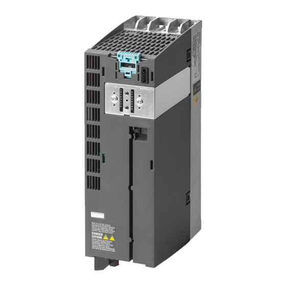
SINAMICS PM230 (IP20) Power Module
Avvertenza
Questo apparecchio conduce tensioni pericolose ed aziona parti meccaniche rotanti
potenzialmente pericolose.
I morsetti possono condurre tensioni pericolose anche quando il convertitore è stato
spento. Dopo avere interrotto l'alimentazione di rete, attendere almeno 5 minuti finché
l'apparecchio non si è scaricato. Solo allora si possono eseguire interventi
sull'apparecchio.
Leggere le istruzioni riportate nei rispettivi manuali all'indirizzo:
http://support.automation.siemens.com. In caso di non osservanza o di mancata
applicazione delle istruzioni sussiste la possibilità di morte, gravi lesioni fisiche o ingenti
danni materiali.
Solo personale qualificato può essere addetto alla messa in servizio e al funzionamento
di questo apparecchio. Per personale qualificato si intendono persone autorizzate a
mettere in servizio, mettere a terra e contrassegnare sistemi e circuiti elettrici in
conformità agli standard della tecnica di sicurezza.
Il funzionamento corretto e sicuro dell'apparecchio presuppone un trasporto,
un'installazione, un utilizzo e una manutenzione appropriati.
PM230 IP20 Push-Through mounting sequence
Width
D2
Mounting hole for mounting frame
Panel template and mounting
holes for PT housing
D1
D2
a
b
c
d
117.7
53.1
103
106
88
198
117.7
53.1
147.5
134
116
304
117.7
53.1
123
174
156
365
Advertencia
El presente equipo está sometido a tensiones peligrosas y controla piezas mecánicas
rotación que también pueden ser peligrosas.
Los bornes o terminales de conexión pueden estar también bajo tensión eléctrica
peligrosa incluso aunque el convertidor o variador no esté funcionando. Tras
desconectar la alimentación de red, espere al menos 5 minutos para que el equipo
pueda descargarse. Sólo entonces proceda a realizar los trabajos de montaje.
Respete las indicaciones que se especifican en las instrucciones de servicio asociadas,
y que pueden consultarse en: http://support.automation.siemens.com. Si no se
observan las advertencias o no se siguen las indicaciones de las instrucciones, existe
peligro de muerte, graves lesiones corporales o considerables daños materiales
La puesta en marcha y el funcionamiento de este equipo debe encomendarse
exclusivamente a personal cualificado. Personal cualificado son personas autorizadas
para poner en servicio, conectar a tierra e identificar sistemas y circuitos eléctricos
conforme a las normas en materia de seguridad.
El funcionamiento correcto y seguro del equipo presupone un transporte, instalación,
montaje y puesta en marcha adecuados, así como un manejo y un mantenimiento
rigurosos.
Mounting Frame
Seal
Cabinet
Push-Through mounting frame
It is recommended that the optional mounting frame
is used to install the Push-through Power Module in
a cabinet. This optional mounting frame is designed,
in conjunction with, the supplied seal to easily
maintain an IP54 rating of the enclosure (the seal is
delivered with the Power Module). If the Power
Module is mounted without using the optional
mounting frame, it is the user's responsibility to
ensure the correct IP protection rating is reached.
Mounting Frame
e
27
34.5
30.5
-1-
Advertisement

Related Manuals for Siemens SINAMICS PM230


Summary of Contents for Siemens SINAMICS PM230
- Page 1 Hinweise können Tod, schwere Körperverletzungen oder erheblicher Sachschaden disponibles sous le lien suivant : http://support.automation.siemens.com. Le non-respect http://support.automation.siemens.com. In caso di non osservanza o di mancata y que pueden consultarse en: http://support.automation.siemens.com.
- Page 2 Short Circuit Current Rating (SCCR) 65 kA Star and Delta connection Mains and Motor terminals FSA ... FSC Screening methods Inside the terminal box of Siemens motors The Power Modules are fitted is a diagram showing both methods of with two-part-connectors. The connections:...
Need help?
Do you have a question about the SINAMICS PM230 and is the answer not in the manual?
Questions and answers