IAI XSEL Operation Manual
P/q/pct/qct type
Hide thumbs
Also See for XSEL:
- Operation manual (535 pages) ,
- Operating manual (135 pages) ,
- Operation manual (149 pages)
Table of Contents
Advertisement
Advertisement
Table of Contents

Related Manuals for IAI XSEL


Summary of Contents for IAI XSEL
- Page 1 XSEL Controller P/Q/PCT/QCT Type Operation Manual Nineteenth Edition...
- Page 4 CAUTION Operator Alarm on Low Battery Voltage This controller is equipped with the following backup batteries for retention of data in the event of power failure: [1] System-memory backup battery For retention of position data, global variables/flags, error list, strings, etc. [2] Absolute-encoder backup battery (optional) For retention of rotation data (when an absolute encoder is used) Since these batteries are not rechargeable, they will be eventually consumed.
- Page 5 Therefore, it may cause early degradation on the internal components if turning on/off of the power and turning on/off of the drive power due to emergency stop input are conducted frequently. Contact IAI in case it is necessary to establish a system to allow frequent turning on/off of the power inevitably.
- Page 6 For a controller with expanded CPU unit memory, use the PC software or teaching pendant of an applicable version as specified below. Teaching tool Version XSEL PC software V7.2.0.0 or later Teaching pendant SEL-T/TD V1.01 or later [How to check if the controller memory has been expanded] Check in the PC software (Ver.
- Page 7 Safety Guide Safety Precautions for Our Products...
- Page 8 Operation Description Description Transportation When carrying a heavy object, do the work with two or more persons or utilize equipment such as crane. When the work is carried out with 2 or more persons, make it clear who is to be the leader and who to be the follower(s) and communicate well with each other to ensure the safety of the workers.
- Page 9 Operation Description Description Installation (2) Cable Wiring and Start for connecting between the actuator and controller, and for the teaching tool. Do not scratch on the cable. Do not bend it forcibly. Do not pull it. Do not coil it around. Do not insert it. Do not put any heavy thing on it. Failure to do so may cause a fire, electric shock or malfunction due to leakage or continuity error.
- Page 10 Operation Description Description Installation (4) Safety Measures and Start When the work is carried out with 2 or more persons, make it clear who is to be the leader and who to be the follower(s) and communicate well with each other to ensure the safety of the workers. When the product is under operation or in the ready mode, take the safety measures (such as the installation of safety and protection fence) so that nobody can enter the area within t...
- Page 11 Operation Description Description Trial Operation When the work is carried out with 2 or more persons, make it clear who is to be the leader and who to be the follower(s) and communicate well with each other to ensure the safety of the workers. After the teaching or programming operation, perform the check operation one step by one step and then shift to the automatic operation.
- Page 12 Operation Description Description Maintenance When the work is carried out with 2 or more persons, make it clear who is and Inspection to be the leader and who to be the follower(s) and communicate well with each other to ensure the safety of the workers. Perform the work out of the safety protection fence, if possible.
- Page 13 Alert Indication...
-
Page 19: Table Of Contents
Table of Contents Introduction ........................1 Part 1 Installation ......................3 Chapter 1 Safety Precautions ....................... 3 Chapter 2 Warranty ..........................4 Warranty Period ........................4 Scope of the Warranty ......................4 Honoring the Warranty ......................4 Limited Liability ........................4 Conditions of Conformance with Applicable Standards/Regulations, Etc., and Applications ........................ - Page 20 When the System-Memory Backup Battery is Not Used ..........119 Points to Note ........................121 Chapter 2 XSEL Language Data ...................... 123 Values and Symbols Used in SEL Language ..............123 List of Values and Symbols Used ................123 I/O Ports ........................124 Virtual I/O Ports .......................
- Page 21 1.13 Structural IF ......................243 1.14 Structural DO ......................246 1.15 Multi-Branching ....................... 248 1.16 System Information Acquisition ................252 1.17 Zone ........................255 1.18 Communication ....................... 259 1.19 String Operation ...................... 265 1.20 Palletizing-Related ....................274 1.21 Palletizing Calculation Command ................288 1.22 Palletizing Movement Command ................
- Page 22 10. Pulse I/O Board Output Channel Parameters ............465 11. Manual Operation Types ..................466 12. Use Examples of Key Parameters ................467 Combination Table of XSEL Linear/Rotary Control Parameters ..........474 Error Level Control ........................475 Error List ..........................530 Troubleshooting of XSEL Controller ..................
-
Page 23: Introduction
Specification (Note) XSEL-P/PCT Standard (Note) XSEL-Q/QCT Note XSEL-PCT and XSEL-QCT are dedicated for CT4 Actuator. For other actuators, use XSEL-P or XSEL-Q. Refer to the following table for details on type specification. Type Example of type specification (Axis 1) (Axis 2) - Page 24 Even after the power is turned off, the internal circuits will continue to carry high voltages for a short period. About actuator duty IAI recommends that our actuators be used at a duty of 50% or less as a guideline in view of the relationship of service life and precision: Accelerati...
-
Page 25: Part 1 Installation
Chapter 1 Safety Precautions The XSEL Controller can be combined with a maximum of six actuators of different types, and is able to provide integrated control over the entire system including peripherals. In other words, the XSEL Controller has the ability to control systems of all sizes ranging from a small system to a large factory automation system. -
Page 26: Chapter 2 Warranty
Part 1 Installation Chapter 2 Warranty Warranty Period One of the following periods, whichever is shorter: 18 months after shipment from our company 12 months after delivery to the specified location Scope of the Warranty Our products are covered by warranty when all of the following conditions are met. Faulty products covered by warranty will be replaced or repaired free of charge: (1) The breakdown or problem in question pertains to our product as delivered by us or our authorized dealer. -
Page 27: Conditions Of Conformance With Applicable Standards/Regulations, Etc., And Applications
Part 1 Installation Conditions of Conformance with Applicable Standards/Regulations, Etc., and Applications (1) If our product is combined with another product or any system, device, etc., used by the customer, the customer must first check the applicable standards, regulations and/or rules. The customer is also responsible for confirming that such combination with our product conforms to the applicable standards, etc. -
Page 30: Selection Of Auxiliary Power Devices
This section provides selection guidelines for breakers, earth leakage breakers, contactors, surge absorbers and noise filters that can be used with the AC power-supply line of the XSEL controller. These devices must be selected by taking into consideration the power consumption, rush current and maximum motor drive current of the controller. - Page 32 Kitagawa Industries [5] Surge absorber With both the global specification and standard specification, the motor drive part of the XSEL controller has no built-in surge absorber to protect the equipment against surge noises that may generate in the controller due to lightning, etc.
- Page 33 Part 1 Installation Peripheral Configurations Three-phase power supply specification P/PCT Type (Standard Specification) Encoder cable Actuator Motor cable 200-VAC Control panel Clamp Ring three- filters core phase power bus Three- Earth phase Circuit leakage noise 24-VDC breaker Brake breaker filter power Controller supply...
- Page 34 Part 1 Installation Peripheral Configurations Single-phase power supply specification P/PCT Type (Standard Specification) Encoder cable Actuator Motor cable 200-VAC Control panel Clamp Ring single- filters core phase power bus Single- Earth phase Circuit leakage 24-VDC noise breaker Brake breaker filter power Controller supply...
-
Page 35: Noise Control Measures And Grounding
If you wish to extend the motor cable or encoder cable beyond the length of each supplied cable, please contact IAI’ s Technical Service Section or Sales Engineering Section. (2) Noise-elimination grounding... -
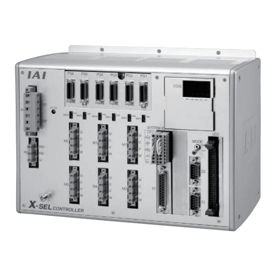
Page 38: Chapter 4 Name And Function Of Each Part
Part 1 Installation Chapter 4 Name and Function of Each Part Front View of Controller P/PCT Type (Standard Specification), 4 axes P/PCT Type (Standard Specification), 4 axes with expansion I/O board and brake unit... - Page 39 Part 1 Installation Q/QCT Type (Global Specification), 4 axes Q/QCT Type (Global Specification), 4 axes with expansion I/O board and brake unit...
- Page 43 Note 1: The safety gate switch will not function if this switch is not set correctly. Note 2: Q/QCT type controllers connot be used with IAI’s standard teaching pendants and standard personal computer cable (black). Note 3: The TP switch is not provided on Q/QCT type controllers.
- Page 44 Part 1 Installation (9) Teaching connector The teaching interface connects IAI’s teaching pendant or a PC (PC software) to enable operation and setting of your equipment from the teaching pendant/PC. The physical interface consists of a RS232C system based on a 25-pin, D-sub connector. The signal level conforms to RS232C, and a desired baud rate (up to 115.2 kbps) can be selected...
- Page 46 Part 1 Installation (10) System I/O connector This I/O connector is used to control the safety actions of the controller. With the global specification, a safety circuit conforming to a desired safety category of up to level 4 can be configured using this connector and an external safety circuit.
- Page 47 Part 1 Installation (11) Panel window This window consists of a 4-digit, 7-segment LED display and five LED lamps that indicate the status of the equipment. For the information shown on the display, refer to 2, “Explanation of Codes Displayed on the Panel Window” or the “Error Code Table.” Meanings of Five LEDs Name Status when the LED is lit...
- Page 50 Part 1 Installation (19) Supplementary Power It is a 24V DC input connector to for brake releasing and driving*. Source (for brake, etc.) When an actuator equipped with a brake or that necessary to supply power Input Connector from this connector is to be connected, supply external 24V DC. For wiring, use shielded cables and connect the shield on the 24V power source side.
-
Page 55: Chapter 5 Specifications
15-bit incremental encoder (Wire-saving type) Position detection methods 15-bit rotation data backup absolute encoder Both have a control resolution of 14 bits (16384 pulses) For backup of absolute data: AB-5 by IAI Batteries For backup of system memory: CR2032 Speed setting 1 mm/sec to 3000 mm/sec (Varies depending on the model used.) - Page 56 RS232C port for teaching Enabled only in the manual operation mode. serial interface IAI’s dedicated teaching pendant or ANSI teaching pendant (selected by a switch) Dedicated 2-channel RS232C, 9-pin DTE specification RS232C port for general PC Half-duplex at speeds up to 115.2 kbps (1 channel) or up to 76.8 kbps...
- Page 57 15-bit incremental encoder (Wire-saving type) Position detection methods 15-bit rotation data backup absolute encoder Both have a control resolution of 14 bits (16384 pulses) For backup of absolute data: AB-5 by IAI Batteries For backup of system memory: CR2032 Speed setting...
- Page 58 1000 V and 1 minute, respectively. Note 2) The XSEL-J/K type supports 3000 positions. Note 3) If one RS232C channel is used at a communication speed of 115.2 kbps, use the other channel at 38.4 kbps or below. If these speeds are exceeded, an overrun error or other problems will occur and successful communication cannot be guaranteed.
-
Page 59: External I/O Specifications
Caution If a non-contact circuit is connected externally, malfunction may result from leakage current. Use a circuit in which leakage current in a switch-off state does not exceed 1 mA. XSEL controller’s input signal ON duration OFF duration At the default settings, the system recognizes the ON/OFF durations of input signals if they are approx. - Page 61 Caution If a non-contact circuit is connected externally, malfunction may result from leakage current. Use a circuit in which leakage current in a switch-off state does not exceed 1 mA. XSEL controller’s input signal OFF duration ON duration At the default settings, the system recognizes the ON/OFF durations of input signals if they are approx.
-
Page 63: Power-Source Capacity And Heat Output
D. Supplemental power input (Power source to release brake and drive actuator) It is necessary to supply 24V DC when connecting an actuator equipped with a brake or that recommended by IAI. Recommended actuator (as of January, 2014): CT4 Pick & Rotary Actuator... - Page 64 Part 1 Installation Table 2. Motor Drive Powers and Output Losses (P/Q/PCT/QCT Types) Control power supply External power source Internal External Internal External Quantity consumption consumption consumption consumption [VA] [VA] [VA] [VA] Base part 31.4 Driver Per board 6.26 1 to 3 Encoder Per axis 2.38...
- Page 65 Actuator for axis 2: 200 W Actuator for axis 3: 100 W with brake Actuator for axis 4: 60 W Standard controller with standard DIO Options: DeviceNet, teaching pendant (IAI’s standard type) [1] Control power-supply capacity {31.14 + 6.26 2 + (2.38 + 3.57) 4 + 4.57...
- Page 66 Part 1 Installation (3) Calculating the wattage of each actuator that can be connected to a single-phase specification system For LSA (Linear Actuator) and DD (Direct Drive Motor) to connect to the single phase type, calculate the wattage from “Output for controller wattage calculation” in the table below. Also, make selection to have the total wattage of LSA, DD and other actuators at 1600W or less. 1600W ≥ LSA Total wattage of LSAs (Output for controller wattage calculation × Number of axes) + Wattage of DD (Output for controller wattage calculation) + Wattage of other actuators (Motor wattage × Number of axes) Wattage Calculation Table for LSA and DD in Single Phase Type Actuator model...
-
Page 67: External Dimensions
Part 1 Installation External Dimensions P/Q/PCT/QCT Type (Three-phase Standard Specification, Single-phase Global Specification, Single-phase Standard Specification) 4-axis Controller External views of enclosures for various 4-axis controllers are shown below (the external enclosure dimensions are the same for 1-axis to 4-axis controllers). Fig. - Page 68 Part 1 Installation Fig. 4-3 P/Q/PCT/QCT Type 4-axis Controller with Expansion I/O Board (Incremental Specification) (Three- phase Standard Specification, Single-phase Global Specification, Single-phase Standard Specification) 33 8 Fig. 4-4 P/Q/PCT/QCT Type 4-axis Controller with Expansion I/O Board + Absolute Brake Unit (Three-phase Standard Specification, Single-phase Global Specification, Single-phase Standard Specification)
- Page 69 Part 1 Installation P/Q/PCT/QCT Type (Standard Specification) 6-axis Controller (Three-phase Standard Specification, Single-phase Global Specification, Single-phase Standard Specification) External views of enclosures for various 6-axis controllers are shown below (the external enclosure dimensions are the same for 5-axis and 6-axis controllers). Fig.
- Page 70 Part 1 Installation Fig. 4-7 P/Q/PCT/QCT Type 4-axis Controller with Expansion I/O Board (Incremental Specification) (Three- phase Standard Specification, Single-phase Global Specification, Single-phase Standard Specification) 58 .5 58.5 Fig. 4-8 P/Q/PCT/QCT Type 6-axis Controller with Expansion I/O Board + Absolute Brake Unit (Three-phase Standard Specification, Single-phase Global Specification, Single-phase Standard Specification) 78.5 78.5...
- Page 71 Part 1 Installation Q/QCT Type (Three-phase Global Specification) 4-axis Controller External views of enclosures for various 4-axis controllers are shown below (the external enclosure dimensions are the same for 1-axis to 4-axis controllers). Fig. 4-9 Q/QCT Type 4-axis Controller (Incremental Specification) (Three-phase Global Specification) (80) 125.3 Fig.
- Page 72 Part 1 Installation Fig. 4-11 Q/QCT Type 4-axis Controller with Expansion I/O Board (Incremental Specification) 64.5 64.5 Fig. 4-12 Q/QCT Type 4-axis Controller with Expansion I/O Board + Absolute Brake Unit 29.5 29.5...
- Page 73 Part 1 Installation Q/QCT Type (Three-phase Global Specification) 6-axis Controller External views of enclosures for various 6-axis controllers are shown below (the external enclosure dimensions are the same for 5-axis and 6-axis controllers). Fig. 4-13 Q/QCT Type 6-axis Controller (Incremental Specification) (Three-phase Global Specification) (80) 45.5 45.5...
- Page 74 Part 1 Installation Fig. 4-15 Q/QCT Type 6-axis Controller with Expansion I/O Board (Incremental Specification) (Three-phase Global Specification) 33 0 Fig. 4-16 Q/QCT Type 6-axis Controller with Expansion I/O Board + Absolute Brake Unit (Three-phase Global Specification)
-
Page 75: Chapter 6 Safety Circuit
5. Applying voltage to the system I/Os The safety circuit of the XSEL controller is designed to operate with 24 VDC. Therefore, never apply 100 or 200 VAC to the system I/Os. Doing so may damage the internal circuits of the controller. -
Page 76: Safety Circuit For P/Pct Type (Standard Specification) Controller
Note, however, that redundant safety circuits cannot be configured even if an ANSI teaching pendant is used. Set the teaching-pendant type switch located above the teaching connector to the position appropriate for the teaching pendant used. Set the switch to the left for an ANSI teaching pendant, or to the right for IAI’s standard teaching pendant. - Page 77 The RDYOUT contacts will close only when the controller has started properly. By connecting these contacts in series with similar contacts of other equipment, the soundness of the entire system can be checked easily. P/PCT type XSEL controller External emergency-stop circuit...
-
Page 78: Safety Circuit For Q/Qct Type (Global Specification) Controller
It is recommended that the control power supply be wired from the same power source as the motor power supply at a point before the drive-source cutoff part is connected. Please note that IAI is not liable for any losses arising from a malfunction of the safety circuit configured by the user. - Page 79 (DET) provides an input for detecting malfunction of the safety circuit (mainly fused relay contacts). Be sure to use this signal if you want the XSEL controller to detect fused contacts. If the safety circuit is configured as a closed system to manage fused contacts and other problems independently, safety category 4 can be met without connecting this signal to the controller.
- Page 81 Part 1 Installation Q/QCT Type XSEL Controller Power supply part Digital control part Contact Rating: 0.2A max. (for inductive load) Not installed External emergency-stop reset contact output AC cutoff relay DC bus Rectifier To power stage Power-on reset MPSDWN bit...
- Page 82 Part 1 Installation External Emergency-Stop Circuit SDN Out– SDN Out+ 200-VAC, three- phase Relay Contactor (NEO SC) Contactor (NEO SC) DET +24V DET IN Reset switch External emergency-stop switch EMG line+ External Safety relay unit EMG switch (G9SA-301 by Omron) contact 1 EMG line–...
-
Page 83: Safety Circuit Timing Charts For Q/Qct Type Sel Controller
Part 1 Installation Safety Circuit Timing Charts for Q/QCT type SEL Controller Safety circuit timing charts for Q/QCT type SEL controller are shown below. The timings covered by the timing charts are as follows: [1], “Power on,” [2], “Emergency stop,” [3], “Power on during emergency stop,”... -
Page 92: Chapter 7 System Setup
Note 2: When connecting a teaching pendant or PC cable (PC software), set the teaching-pendant type switch to an appropriate position. Left: ANSI teaching pendant Right: IAI’s standard teaching pendant or PC cable... - Page 93 PC cable (PC software) is connected to this connector. Warning : The internal components of the controller may burn if the following cable is used to connect XSEL-Q/QCT to a computer. • Standard PC cable CB-ST-E1MW050 (black) enclosed in PC Software IA-101-X-MW Even though the PC software can be used, make sure to use the cable CB-ST-A1MW050 (gray).
- Page 94 4. Set the teaching-pendant type switch. (Note 1) Q/QCT type controllers have no TP-SW. (Note 2) Q/QCT type controllers cannot be used with IAI’s standard teaching pendants or standard PC cables. Left: SEL-T, SEL-TD, SEL-TG teaching pendant IA-T-XA teaching pendant...
- Page 98 300 (area 2) to 315 (area 2) whose functions have been set by I/O parameter Nos. 331 to 346, “Output function selection *** (area 2).” Note: The above functions are supported by XSEL PC software of V7.2.0.0 or later. (1) Assignment example of input function selection Given below is an example of assigning input function selection 000 (program start) whose function has been set by I/O parameter No.
-
Page 107: Chapter 8 How To Perform An Absolute Encoder Reset (Absolute Specification)
Procedure (1) Turn off the XSEL Controller power. Turn on the PC power and wait for the operating system to be started. (2) Connect the 9-pin, D-sub connector on one end of the connection cable to the communication port on the PC, and connect the 25-pin, D-sub connector on the other end to the 25-pin communication port on the controller. - Page 108 Part 1 Installation (6) The XSEL PC software window will be displayed. Clicking the [OK] button will clear the error message. (7) From the [Monitor] menu, select [Detailed Error Information] to check the current error status. In the case of an encoder battery error, the following will be displayed (when axis 4 is using an absolute encoder).
- Page 111 (17) This completes the absolute encoder reset. To redo the absolute encoder reset, exit the XSEL PC software and repeat the procedure from the beginning. (Caution) On certain models, the current value may not return to “0” mm after an absolute encoder reset.
-
Page 127: Chapter 9 Maintenance
Battery Backup Function” in Appendix. Memory backup The XSEL Controller saves program, position and parameter data to its flash memory (when written to the flash memory). The data saved by the battery includes position data, SEL global data, error list and content of the user-data backup memory in the controller with expanded memory (with gateway function). -
Page 128: Replacement Procedure For System-Memory Backup Battery
If “Other parameter No. 20, Backup-battery installation function type” is set to “2” (installed), the following SRAM data in the XSEL Controller will be backed up by the system-memory backup battery on the panel board: Position data (positions from Nos. 1 to 10000 in the case of a controller with expanded memory (with gateway... -
Page 133: Part 2 Operation
How to Start a Program With the XSEL Controller, the stored programs can be started (run) using four methods. Of these methods, two are mainly used to debug programs or perform trial operations, while the remaining two are used in general applications on site. -
Page 134: Starting A Program By Auto-Start Via Parameter Setting
Part 2 Operation Starting a Program by Auto-Start via Parameter Setting I/O parameter No. 33 (input function selection 003) = 1 (default factory setting) This parameter is set using the teaching pendant or PC software. Set the number of the program you wish to start automatically in other parameter No. -
Page 138: Part 3 Controller Data Structure
Part 3 Controller Data Structure Part 3 Controller Data Structure The controller data consists of parameters as well as position data and application programs used to implement SEL language. XSEL Controller Data Structure Main Driver Driver Driver Driver SEL language... -
Page 139: Chapter 1 How To Save Data
Part 3 Controller Data Structure Chapter 1 How to Save Data Since the XSEL Controller uses flash memory, some data are saved by battery backup while others are saved in the flash memory. When data is transferred from the PC software or teaching pendant to the controller, the data is only written to the main CPU memory as shown in the diagram below and will be erased once the controller is powered down or reset. - Page 140 Main CPU flash memory Write to flash memory Programs Parameters (other than Transfer upon reset slave parameters) Transfer Symbols Position (XSEL axes) (Nos. 10001 to 20000) Write to flash memory Transfer Slave card Transfer upon reset parameters (variable driver parameters)
- Page 142 Main CPU flash memory Programs Parameters (other than Write to flash memory slave parameters) Transfer Symbols Transfer upon reset Position (XSEL axes) (Nos. 1 to 20000) Write to flash memory User-data backup Transfer memory Transfer upon reset (Positions (RC axes))
-
Page 145: Chapter 2 Xsel Language Data
Part 3 Controller Data Structure Chapter 2 XSEL Language Data Values and Symbols Used in SEL Language List of Values and Symbols Used The various functions required in a program are represented by values and symbols. Function Global range Local range... -
Page 146: I/O Ports
Integers and real numbers can be used. However, pay due attention to the following limitations: Numeric data The XSEL Controller can handle values of maximum eight digits including a sign and a decimal point. Integer: -9,999,999 to 99,999,999 Real number: Maximum eight digits including a sign and decimal point, regardless of the size of value Example) 999999.9, 0.123456, -0.12345... -
Page 148: Virtual I/O Ports
Part 3 Controller Data Structure Port No. Function 7164 Running program No. 64 (including during pause) 7165 Running program No. 65 (including during pause) (Controller with expanded memory (with gateway function) only) 7228 Running program No. 128 (including during pause) (Controller with expanded memory (with gateway function) only) 7229 to 7299 (For future expansion = Use strictly prohibited) -
Page 155: Symbols
Part 3 Controller Data Structure Symbols In the XSEL Controller, values such as variable numbers and flag numbers can be handled as symbols. For the method to edit symbols, refer to “Editing Symbols” in the operation manual for XSEL teaching pendant or “Symbol Edit Window”... -
Page 158: Position Part
Part 3 Controller Data Structure XSEL language consists of a position part (position data = coordinates, etc.) and a command part (application program). Position Part As position data, coordinates, speeds, accelerations and decelerations are set and stored. Standard 0.3 G... -
Page 161: Part 4 Commands
Part 4 Commands Part 4 Commands Chapter 1 List of SEL Language Command Codes 1. By Function Variables can be specified indirectly in the operand 1, operand 2 and output fields. Symbols can be input in the condition, operand 1, operand 2 and output fields. The input items in ( ) under operand 1 and operand 2 are optional. - Page 162 Part 4 Commands Operation type in the output field CC: Command was executed successfully, ZR: Operation result is zero, PE: Operation is complete, CP: Command part has passed, TU: Time up EQ: Operand 1 = Operand 2, NE: Operand 1 Operand 2, GT: Operand 1 >...
- Page 163 Part 4 Commands Operation type in the output field CC: Command was executed successfully, ZR: Operation result is zero, PE: Operation is complete, CP: Command part has passed, TU: Time up EQ: Operand 1 = Operand 2, NE: Operand 1 Operand 2, GT: Operand 1 >...
- Page 164 Part 4 Commands Operation type in the output field CC: Command was executed successfully, ZR: Operation result is zero, PE: Operation is complete, CP: Command part has passed, TU: Time up EQ: Operand 1 = Operand 2, NE: Operand 1 Operand 2, GT: Operand 1 >...
- Page 165 Part 4 Commands Operation type in the output field CC: Command was executed successfully, ZR: Operation result is zero, PE: Operation is complete, CP: Command part has passed, TU: Time up EQ: Operand 1 = Operand 2, NE: Operand 1 Operand 2, GT: Operand 1 >...
- Page 166 Part 4 Commands 2. Alphabetical Order Operation type in the output field EQ: Operand 1 = Operand 2, NE: Operand 1 Operand 2, CC: Command was executed successfully, GT: Operand 1 > Operand 2, GE: Operand 1 Operand 2, Operation result is zero, PE: Operation is complete, CP: Command part has passed, TU: Time up Operand 1 <...
- Page 167 Part 4 Commands Operation type in the output field CC: Command was executed successfully, ZR: Operation result is zero, Operation is complete, CP: Command part has passed, TU: Time up EQ: Operand 1 = Operand 2, NE: Operand 1 Operand 2, GT: Operand 1 >...
- Page 168 Part 4 Commands Operation type in the output field CC: Command was executed successfully, ZR: Operation result is zero, Operation is complete, CP: Command part has passed, TU: Time up EQ: Operand 1 = Operand 2, NE: Operand 1 Operand 2, GT: Operand 1 >...
- Page 169 Part 4 Commands Operation type in the output field CC: Command was executed successfully, ZR: Operation result is zero, Operation is complete, CP: Command part has passed, TU: Time up EQ: Operand 1 = Operand 2, NE: Operand 1 Operand 2, GT: Operand 1 >...
- Page 170 Part 4 Commands Operation type in the output field CC: Command was executed successfully, ZR: Operation result is zero, Operation is complete, CP: Command part has passed, TU: Time up EQ: Operand 1 = Operand 2, NE: Operand 1 Operand 2, GT: Operand 1 >...
- Page 171 Part 4 Commands RC Gateway Function Commands (Controller with Gateway Function Only) For commands relating to the RC gateway function, refer to the “Operation Manual for XSEL Controller P/Q/PCT/QCT/ PX/QX RC Gateway Function.” Operation type in the output field EQ: Operand 1 = Operand 2, NE: Operand 1...
-
Page 172: Commands
Commands Relating to Electronic Cam Function (Applicable only to controllers with electronic cam function) * For the details of electronic cam commands, refer to the “Operation Manual for XSEL Controller P/Q/PCT/QCT: Electronic Cam Function.” Operation type in the output field... - Page 226 S-shaped Motion Effective Setting in Operation 2 Model Name S-shaped Motion Class Command Group (S-shaped Type) (See the table below) Not set, 0 XSEL-P/Q (Note 2) (Note 2) Not set, 0 (Note 1) XSEL-PCT/QCT (Note 2) (Note 2) Note 1 The class of S-shaped motion is compulsorily B.
- Page 230 [Example] Express what axis is to be used by using either “1” or “0”. (Host) (Slave) Axis No. 6-axis 5-axis 4-axis 3-axis 2-axis 1-axis Unused 2-axis It should be 000011… (0 in front are not necessary. Remove 0 and make it 11.) 1-axis 4-axis It should be 1001…...
- Page 234 Indication Error”. Indicate the acceleration and deceleration in ACC, DCL Command and the position data. (Note 6) This command language is applicable for XSEL-P/Q/PCT/QCT controller main application Ver. 1.15 and later. It is available to input for PC software Ver. 7.07.04.00 and later.
- Page 235 Part 4 Commands Example for Use Example. 1 For arch motion movement (vertical axis to move up/down) VLMX Set the speed setting in VLMX Speed. ACMX Set the ACMX acceleration/deceleration of No.1. ACHZ Indicate the 3rd axis to Z-axis for arch motion. ATRG ARCH With Position No.12 as the peak point, move with the arch motion to...
- Page 236 Part 4 Commands Example. 2 When the transported weight differs for going forward and backward VLMX Set the speed setting in VLMX Speed. ACMX Set the ACMX acceleration/deceleration of No.1. MOVP PTP movement is made to Position No.10. ACMX Set the ACMX acceleration/deceleration of No.2. MOVP PTP movement is made to Position No.11.
- Page 246 Part 4 Commands MVPI (Move via incremental PTP) Command, declaration Extension condition Input condition Output Command, (LD, A, O, AB, OB) (I/O, flag) (Output, flag) Operand 1 Operand 2 declaration Position Optional Optional MVPI Prohibited number [Function] Move the actuator, without interpolation, from the current position by the travel distance corresponding to the position number specified in operand 1.
- Page 247 Part 4 Commands MVLI (Move via incremental interpolation) Command, declaration Extension condition Input condition Output Command, (LD, A, O, AB, OB) (I/O, flag) (Output, flag) Operand 1 Operand 2 declaration Position Optional Optional MVLI Prohibited number [Function] Move the actuator, with interpolation, from the current position by the travel distance corresponding to the position number specified in operand 1.
- Page 249 Part 4 Commands (Jog) Command, declaration Extension condition Input condition Output Command, (LD, A, O, AB, OB) (I/O, flag) (Output, flag) Operand 1 Operand 2 declaration Input, Axis Optional Optional output, flag pattern number [Function] The axes in the axis pattern specified in operand 1 will move forward or backward while the input or output port or flag specified in operand 2 is ON or OFF.
-
Page 281: 1.18 Communication
Part 4 Commands 1.18 Communication OPEN (Open channel) Command, declaration Extension condition Input condition Output Command, (LD, A, O, AB, OB) (I/O, flag) (Output, flag) Operand 1 Operand 2 declaration Channel Optional Optional OPEN Prohibited number [Function] Open the channel specified in operand 1. The specified channel will be enabled to send/receive hereafter. - Page 284 The WRIT timer setting is effective only for standard SIOs (channel 1 or 2 supporting flow control). TMRD used in the XSEL-J/K type controller is treated as TMRW in the XSEL-P/Q/PCT/QCT type controller. If a program file created for an XSEL-J/K controller is transferred to an XSEL-P/Q/PCT/QCT controller, the PC software will automatically convert “TMRD”...
- Page 285 WRIT command is executed in other task, the response from the other side can be received without delay after the command is sent from the XSEL. (Note 1) CP for channels other than 1 and 2.
- Page 326 If a variable not of the integer type is specified, “C3C: Variable number error” will occur. (Note) Pulse I/O board parameters can be acquired when the parameter type is set to 10. For details, refer to the Operation Manual for “XSEL-P/Q/PCT/QCT Controller: Electronic Cam Function.” [Example] LET 1250 Variable No.
-
Page 332: Chapter 4 Palletizing Function
Part 4 Commands Chapter 4 Palletizing Function The SEL language used by the XSEL Controller provides palletizing commands that support palletizing operation. These commands allow simple specification of various palletizing settings and enable arch motion ideal for palletizing. How to Use... -
Page 338: Palletizing Calculation
With XSEL commands, executing a “get palletizing angle” command following a palletizing setting via 3- point teaching will automatically obtain the palletizing angle. -
Page 349: Chapter 5 Pseudo-Ladder Task
Part 4 Commands Chapter 5 Pseudo-Ladder Task With the XSEL Controller, a pseudo-ladder task function can be used depending on the command and extension condition. The input format is shown below. Note that this function must be used by expert engineers with a full knowledge of PLC software design. - Page 353 Part 4 Commands (2) Explanation of the operation 1. Wait for the axis-1 movement pushbutton switch to turn ON. 2. The X-axis moves while the pushbutton switch is ON, and stops when the switch turns OFF. 3. Wait for the axis-2 movement pushbutton switch to turn ON. 4.
- Page 354 Part 4 Commands (3) XSEL Controller application program Step Cmnd Operand 1 Operand 2 Comment Axes 1 and 2 return to home HOME (servo ON). Set speed to 400 mm/s. Wait for input from axis-1 WTON movement switch. Move forward while axis-1 JFWN movement switch is ON.
- Page 356 Part 4 Commands (2) Explanation of the operation 1. The XY-table moves to the operation home (P1) and waits. 2. The operator sets a load on the XY-table and turns on the start switch. 3. The XY-table moves to riveting position No. 1 (P2) on the work part and a riveting command is output to the riveter.
- Page 357 Part 4 Commands (3) XSEL Controller application program Step Cmnd Operand 1 Operand 2 Comment XY-table returns to home HOME (servo ON). Set speed to 400 mm/s. Move to position No. 1 (home MOVL of work). Set 2 in work part counter.
- Page 359 Part 4 Commands (2) Explanation of the operation 1. Move to the standby point and wait for a start input. 2. Move to the work part feed point after a start input is received. 3. The Z-axis comes down and the air chuck clamps the work part. 4.
- Page 360 Part 4 Commands (3) XSEL Controller application program Step Cmnd Operand 1 Operand 2 Comment HOME Axes 1 and 2 return to home. Set speed to 100 mm/s. Acceleration/deceleration: 0.2 G Clear variable. Clear variable. OFST Clear offset value. MOVL Move to position No.
-
Page 361: Part 5 Multi-Tasking
Chapter 1 Real-Time Multi-Tasking SEL Language The XSEL Controller allows integrated control of actuators and peripherals with a single controller using its 32- bit RISC CPU and high-speed real-time operating system. There is no need to learn various languages for different units, such as robot language for robots and sequencer language for peripherals. -
Page 364: Release Of Emergency Stop
An emergency stop is actuated by turning the emergency-stop contact b input to OFF, and released by turning the input to ON. (1) Flow chart (2) Timing chart Emergency stop is Emergency-stop release timing on XSEL Controller actuated Emergency-stop input (contact b) Emergency stop... -
Page 366: Chapter 2 Example Of Building A System
How to build hardware and software is explained in details by using a screw-tightening robot as an example. Equipment Screw-tightening machine (for Z-axis) Actuators (for axes 1 and 2) IAI’s 60-W servo motor with 300-mm stroke x 2 Controller IAI’s XSEL Controller Operation (1) Tighten six screws at 30-mm pitches on axes 1 and 2. - Page 372 Appendix Appendix Actuator Specification List Payload capacity Rated acceleration Stroke (mm) and maximum speed (mm/sec) (Note 1) (Note 2) Model Horizontal Vertical Horizontal Vertical number (Note 1) The figure in each elongated circle indicates the maximum speed for the applicable stroke(s). (Note 2) The payload capacity is based on operation at the rated acceleration.
- Page 373 Appendix...
- Page 375 Appendix...
- Page 377 Appendix...
- Page 378 Position Table Position Table With P/Q/PCT/QCT type XSEL controllers without expanded memory, up to 4000 position points can be registered. With expanded memory, these controllers let you register up to 20000 positions. Positions are registered using the PC software or teaching pendant.
- Page 379 Programming Format Program Edit Screen (PC Software) With XSEL controllers without expanded memory, programs consisting of up to 6000 steps can be created. With expanded memory, these controllers let you create programs consisting of up to 9999 steps. Programs are edited using the PC software or teaching pendant.
- Page 381 Appendix...
- Page 383 Appendix...
- Page 384 Appendix Output Control during Path Movement Description In spray operation, etc., output control may be required while the actuator is moving. The XSEL controller can output signals while the actuator is moving with a PATH command. How to Use Before executing a PATH command, declare a POTP command to specify signal output during movement.
- Page 385 Appendix...
- Page 386 Output a signal to confirm completion of home return (incremental specification or quasi-absolute specification). With the XSEL controller, a home return completion signal can be output using an I/O parameter. However, the following explains how to output a home return completion signal within a program using a general-purpose output.
- Page 387 Appendix...
- Page 388 Change the moving speed. How to Use With the XSEL controller, the speed can be set using the following two methods: a: Use a VEL command within the application program b: Use a speed setting in the position data table...
- Page 389 Appendix...
- Page 390 Backup in Battery The XSEL controller has a built-in battery for retaining variables and flags used in the programs. For both variables and flags, only those in the global range will be retained after the controller power is turned off. The variables and flags in the local range are cleared when the program is started (the variables are reset to “0,”...
- Page 391 Appendix...
- Page 393 Appendix...
- Page 395 Appendix...
- Page 397 Appendix...
- Page 399 Appendix...
- Page 401 Appendix...
- Page 403 Appendix...
- Page 404 (ABPG) simultaneously. Caution The XSEL controller supports multi-tasking. Up to 16 programs can be run at the same time. To use other programs when the controller is already running 16 programs, switch programs by closing a program or programs that are not required.
- Page 405 Appendix...
-
Page 406: Battery Backup Function
A coin-type battery with holder is installed in the panel on the front side of the controller, in order to retain the various data stored in the system memory (SRAM) of the XSEL controller even when the power is cut off, thus effectively implementing a system memory backup. - Page 407 Appendix...
-
Page 408: Absolute-Data Backup Battery
Appendix Absolute-Data Backup Battery If the XSEL controller is to drive an absolute-type actuator, an absolute-data backup battery must be installed in the controller. An absolute encoder is designed to retain rotation data and detect rotations using the power supplied from the absolute-data backup battery, even when the controller’s control power is not supplied, thus allowing the... - Page 409 Appendix Appendix The XSEL controller provides an enable switch for absolute-data backup battery for each controller axis. When replacing any absolute-data backup battery following a battery error, turn the absolute-data backup battery enable/disable switch of the target axis to OFF (the controller power should be turned off during the replacement).
-
Page 411: Operation Of High Speed Cartesian Robot (Ct4)
Appendix Appendix Operation of High Speed Cartesian Robot (CT4) 1. Connectionof Regenerative Resistors The number of necessary regenerative resistors is two pieces. It is capable up to 100W with two resistors when an additional axis such as a gripper is added. 2. -
Page 412: Number Of Regenerative Resistance Units To Be Connected
Regenerative resistance unit: A unit that converts to heat the regenerative current generating when the motor decelerates. [Installation standards] When used horizontally Total sum of motor capacities of connected actuators XSEL-P/Q 0 to 100 W Not required to 600 W 1 unit... -
Page 413: Synchro Function
Appendix... -
Page 414: Absolute Reset Of A Synchro Controller
Appendix... -
Page 415: Position Adjustment Of Synchro-Axis Sliders
Appendix... - Page 416 Appendix...
- Page 417 Appendix...
- Page 418 Appendix...
- Page 419 Appendix...
-
Page 420: Standard Absolute-Reset Procedure
When the master axis = 1 and slave axis = 0 in “Axis-specific parameter No. 38, Encoder ABS/INC type” After completing 2, “Position Adjustment of Synchro-Axis Sliders,” perform an absolute reset for the master axis only. For the operation procedure, refer to the operation manual for the XSEL Controller or PC software. Note) A synchro axis that has been reset by the standard procedure is unable to correct any positional shift that may have occurred while the power was turned off, after the servo is turned on. -
Page 421: Vibration Control Function
Appendix Appendix Vibration Control Function Applicable versions : XSEL-P/Q/PCT/QCT controller main application version 0.90 or later : PC software (IA-101-X-**) version 7.6.1.0 or later (Note) This function cannot be set from a teaching pendant. Natural vibration (resonance) frequencies are attenuated to dampen vibration. - Page 423 Appendix...
- Page 425 Appendix...
-
Page 426: Multiple-Slider Near-Miss Detection (Collision Prevention) Function
Appendix Multiple-Slider Near-Miss Detection (Collision Prevention) Function * Applicable versions: XSEL-P/Q/PCT/QCT controllers of main application version 0.51 or later Teaching pendant main application (IA-T-X, IA-T-XD) version 1.41 or later Teaching pendant main application (IA-T-X) version 1.31 or later PC software (IA-101-X-**) version 7.0.1.0 or later When multiple sliders are used, this function prevents jogging or positioning axes from colliding with one other. - Page 427 Appendix...
- Page 429 Appendix...
- Page 430 Appendix Parameter name Default value Input range Unit Attribute 2 of SIO channel 1 opened to user 0H to 00000001H None (standard mount) FFFFFFFFH Attribute 2 of SIO channel 2 opened to user 0H to 00000001H None (standard mount) FFFFFFFFH Settings Bits 28 to 31: For future expansion...
- Page 431 Appendix...
- Page 433 Appendix...
-
Page 435: List Of Parameters
Appendix... - Page 437 Appendix...
- Page 439 Appendix...
- Page 441 Appendix...
- Page 443 Appendix...
- Page 444 1: Open SEL program (Connect PC/TP when both devices are closed (AUTO mode) = Used exclusively by the manufacturer) 2: IAI protocol B (Slave) Station code of SIO 0 to 255 Valid only with IAI protocol. channel 0 opened to user...
- Page 445 Appendix...
- Page 446 IP address of connection destination and port number of connection destination do not match completely between the IAI protocol B/TCP MANU and AUTO modes, the connection will be cut off when the MANU/AUTO mode is switched. 125 Network attribute 6...
- Page 447 Appendix...
- Page 449 Appendix Appendix I/O Parameters Default value Input Parameter name (Reference) range 201 Attribute 1 of SIO 28100001H 0H to Bits 28 to 31: Baud rate type (0: 9.6, 1: 19.2, 2: 38.4, 3: 57.6, 4: FFFFFFFFH channel 1 opened to 76.8, 5: 115.2 kbps) user (standard mount) If flow control is performed, select 38.4...
- Page 451 Appendix Appendix I/O Parameters Default value Input Parameter name Unit Remarks (Reference) range 215 Attribute 3 of SIO 01118040H 0H to Bits 28 to 31: Flow control type FFFFFFFFH channel 2 opened to (0: None, 1: Xon/Xoff, 2: Hardware) user (standard mount) * Valid only in full-duplex communication.
- Page 453 Appendix...
- Page 455 Appendix...
- Page 457 Appendix...
- Page 459 501 Number of RC-gateway 0 to 512 Number of position data used in the RC position data mode position data points within the XSEL. (Main application version 0.65 or later/F-ROM 32-Mbit version only) 502 Maximum axis number 0 to 15...
- Page 461 Appendix...
- Page 463 Appendix...
-
Page 464: Parameters Common To All Axes
CP is conducted from unspecific position (in such cases as the first point movement) since the distributed acceleration/deceleration speed varies depending on the operation start position. (XSEL-P/Q/PCT/QCT main application Ver. 1.15 or later) (For expansion) Maximum operating speed 0 to 1... - Page 465 Appendix Parameters Common to All Axes Default value Parameter name Input range Unit Remarks (Reference) Minimum emergency 1 to 300 0.01 G Restriction is made for each axis with the setting values above if Each Axis deceleration Parameter No.136 “Minimum Emergency Deceleration for Each Axis” is valid.
- Page 466 Appendix Parameters Common to All Axes Default value Parameter name Input range Unit Remarks (Reference) (For expansion) Reserved by system 1 to 999 0.01 G Reserved by system 1 to 999 0.01 G Reserved by system 1500 1 to 9999 mm/sec Reserved by system 1000...
- Page 467 Appendix Parameters Common to All Axes Default value Parameter name Input range Unit Remarks (Reference) 105 to (For expansion) 110 Reserved by system 4321H 0H to FFFFFFFFH 111 Reserved by system 543103H 0H to FFFFFFFFH 112 Reserved by system 0 ~ 2 113 Reserved by system -9999999 to 0.001...
-
Page 468: Axis-Specific Parameters
• Acceleration of movement in positive direction of the cooperate system • Deceleration of movement in negative direction of the cooperate system Setting is established based on transported weight, installation condition, etc. (XSEL-P/Q/PCT/QCT main application Ver. 1.15 or later) ACMX - acceleration 1 1 to 999 0.01G Acceleration speed when ACMX Command is executed. - Page 469 Appendix Axis-Specific Parameters Default value Parameter name Input range Unit Remarks (Reference) (Phase-Z evacuation distance 1000 0 to 99999 0.001 mm Evacuation distance from the actual phase-Z position (Positive value at absolute home return (old)) = Applied in the direction of moving away from the end) (Phase-shift prevention margin) (Refer to axis-specific parameter No.
- Page 470 Appendix Axis-Specific Parameters Default value Parameter name Input range Unit Remarks (Reference) Synchro setting bit pattern 1 0H to * Effective only when specified for the synchro slave axis. FFFFFFFFH (Main application version 0.62 or later) Bits 8 to 11: Selection of use of Z-phase of the synchro slave axis during home return of the incremental encoder (INC-INC control) (0: Do not use Z-phase of the slave axis 1: Use not use Z-phase of the slave axis)
- Page 471 Appendix Axis-Specific Parameters Default value Parameter name Input range Unit Remarks (Reference) Reference DRVVR (Change prohibited) To maintain symmetry of the positive and negative only sides. DRVVR – offset Reference DRVVR (Change prohibited) To maintain symmetry of the positive and negative only sides.
- Page 472 0.01G Ineffective when set to 0 or below. Restriction is to be made regarding All for Each Axis Axes Parameter No.22 “Maximum Acceleration”. (XSEL-P/Q/PCT/QCT main application Ver. 1.15 or later) 135 Maximum Operation 0 to 999 0.01G Ineffective when set to 0 or below. Restriction is to be made regarding All Deceleration for Each Axis Axes Parameter No.23 “Maximum Deceleration”.
- Page 473 Appendix Axis-Specific Parameters Default value Parameter name Input range Unit Remarks (Reference) 142 Coordinate direction selection 0 to 1 0: Positive coordinate direction of rotational movement axis Positive for rotational movement coordinate direction of linear movement axis axis linear movement axis 1: Positive coordinate direction of rotational movement axis Negative ballscrew spline correction coordinate direction of linear movement axis...
-
Page 475: Driver Card Parameters
Appendix Appendix Driver Card Parameters Default value Parameter name Input range Unit Remarks (Reference) Motor/encoder characteristic 0004H Reference For adjustment by the manufacturer word (compatible with E, only priority on E) (configuration information) Motor/encoder control word 1 5000 Reference For adjustment by the manufacturer (compatible with E, priority on only E) (configuration information) -
Page 477: Encoder Parameters
Appendix... -
Page 479: Other Parameters
Appendix... - Page 481 Appendix...
- Page 483 Bits 0 to 7: System Reservation FFFFFFFFH Bits 8 to 11: Whether to use servo monitoring IO monitor function (0: Not to use, 1: Use) (XSEL-P/Q/PCT/QCT main application Ver. 1.15 or later) Bits 12 to 31: For expansion 48 (For expansion)
-
Page 485: Pulse I/O Board Common Parameters
Appendix... -
Page 487: Pulse I/O Board Output Channel Parameters
Appendix... -
Page 489: Use Examples Of Key Parameters
Appendix... - Page 490 Appendix...
- Page 491 Appendix...
- Page 492 Appendix...
- Page 493 Appendix...
- Page 494 Appendix...
- Page 495 Appendix Appendix...
-
Page 496: Combination Table Of Xsel Linear/Rotary Control Parameters
Appendix Appendix INTELLIGENT ACTUATOR... -
Page 497: Error Level Control
Appendix... - Page 498 Appendix...
- Page 499 Appendix Appendix INTELLIGENT ACTUATOR...
- Page 500 Appendix Appendix INTELLIGENT ACTUATOR...
- Page 501 Appendix Appendix INTELLIGENT ACTUATOR...
- Page 502 Appendix Appendix INTELLIGENT ACTUATOR...
- Page 503 Appendix Appendix INTELLIGENT ACTUATOR...
- Page 504 Appendix Appendix INTELLIGENT ACTUATOR...
- Page 505 Appendix Appendix INTELLIGENT ACTUATOR...
- Page 506 Appendix...
- Page 507 Appendix...
- Page 508 Appendix...
- Page 509 Appendix...
- Page 510 Appendix...
- Page 511 Appendix...
- Page 512 Appendix...
- Page 513 Appendix Appendix INTELLIGENT ACTUATOR...
- Page 514 Appendix...
- Page 515 Appendix...
- Page 516 Appendix...
- Page 517 Appendix...
- Page 518 Appendix...
- Page 519 Appendix...
- Page 520 Appendix Appendix INTELLIGENT ACTUATOR...
- Page 521 Appendix Appendix INTELLIGENT ACTUATOR...
- Page 522 Appendix Appendix INTELLIGENT ACTUATOR...
- Page 523 Appendix...
- Page 524 Appendix...
- Page 525 Appendix...
- Page 526 Appendix...
- Page 527 Appendix...
- Page 528 Appendix...
- Page 529 Appendix...
- Page 530 Appendix Appendix INTELLIGENT ACTUATOR...
- Page 531 Appendix Appendix INTELLIGENT ACTUATOR...
- Page 532 Appendix Appendix INTELLIGENT ACTUATOR...
- Page 533 Appendix...
- Page 534 Appendix...
- Page 535 Appendix...
- Page 536 Appendix Appendix INTELLIGENT ACTUATOR...
- Page 537 Appendix...
- Page 538 Appendix...
- Page 539 Appendix Appendix INTELLIGENT ACTUATOR...
- Page 540 Appendix...
- Page 541 Appendix...
- Page 542 Appendix...
- Page 543 Appendix Appendix INTELLIGENT ACTUATOR...
- Page 544 Appendix...
- Page 545 Appendix Appendix INTELLIGENT ACTUATOR...
- Page 546 Appendix...
- Page 547 Appendix...
- Page 548 Appendix Appendix INTELLIGENT ACTUATOR...
- Page 549 Appendix Appendix INTELLIGENT ACTUATOR...
- Page 550 Appendix...
- Page 551 Appendix...
-
Page 552: Error List
Appendix... - Page 553 Appendix Appendix INTELLIGENT ACTUATOR...
- Page 554 Appendix...
- Page 555 Appendix Appendix INTELLIGENT ACTUATOR...
-
Page 556: Troubleshooting Of Xsel Controller
Appendix Troubleshooting of XSEL Controller The XSEL Controller has a panel window on its front face. Error numbers will be displayed in this panel window. When the power is turned on, normally “rdy” or “Ardy” will be displayed. “P01” or other code will be displayed while a program is running. - Page 557 Appendix...
- Page 558 Appendix Appendix INTELLIGENT ACTUATOR...
- Page 559 Appendix...
- Page 560 Appendix...
- Page 561 Appendix...
-
Page 562: Trouble Report Sheet
Appendix... -
Page 563: Change History
Important note added for re-execution of absolute reset in synchronizing process March 2012 Thirteenth edition P.70: Warning note added to tell the internal components of XSEL-Q/QCT controller may burn if the enclosed cable CB-ST-E1MW050 (black) is used. March 2012 Fourteenth edition P.1 to 7: Contents added and changed in Safety Guide... - Page 564 Appendix Appendix Revision Date Description of Revision May 2014 Eighteenth edition Applied for CT4 Pick & Rotary Axis Nineteenth edition September 2014 Caution added to MVPI and MVLI Commands, etc.
- Page 566 825 PhairojKijja Tower 12th Floor, Bangna-Trad RD., Bangna, Bangna, Bangkok 10260, Thailand TEL +66-2-361-4458 FAX +66-2-361-4456 The information contained in this document is subject to change without notice for purposes of product improvement. Copyright © 2014. Sep. IAI Corporation. All rights reserved. 14.09.000...
Need help?
Do you have a question about the XSEL and is the answer not in the manual?
Questions and answers