Sign In
Upload
Manuals
Brands
IAI Manuals
Controller
X-SEL
IAI X-SEL Manuals
Manuals and User Guides for IAI X-SEL. We have
6
IAI X-SEL manuals available for free PDF download: Operation Manual, Operating Manual
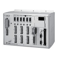
IAI X-SEL Operation Manual (535 pages)
P/Q Type
Brand:
IAI
| Category:
Controller
| Size: 7.71 MB
Table of Contents
Table of Contents
7
Safety Guide
31
Chapter 1 Safety Precautions
33
Part 1 Installation
33
Chapter 2 Warranty Period and Scope of Warranty
34
Warranty Period
34
Scope of Warranty
34
Scope of Service
34
Chapter 3 Installation Environment and Selection of Auxiliary Power Devices
35
Installation Environment
35
Heat Radiation and Installation
36
Selection of Auxiliary Power Devices
37
Noise Control Measures and Grounding
42
Chapter 4 Name and Function of each Part
45
Front View of Controller
45
Explanation of Codes Displayed on the Panel Window
58
Application
58
Core
59
Current Monitor and Variable Monitor
60
Chapter 5 Specifications
62
Controller Specifications
62
P Type (Standard Specification)
62
Q Type (Global Specification)
64
Differences between Q Type (Global Specification) and P Type (Standard Specification)
65
External I/O Specifications
66
NPN Specification
66
PNP Specification
68
Power-Source Capacity and Heat Output
70
External Dimensions
73
P/Q Type
73
P/Q Type (Standard Specification) 6-Axis Controller (Three-Phase Standard Specification, Single-Phase Global Specification, Single-Phase Standard Specification)
75
Q Type (Three-Phase Global Specification) 4-Axis Controller
77
Q Type (Three-Phase Global Specification) 6-Axis Controller
79
Chapter 6 Safety Circuit
81
Items to Notes
81
Safety Circuit for P Type (Standard Specification) Controller
82
Safety Circuit for Q Type (Global Specification) Controller
84
Safety Circuit Timing Charts for Q-Type SEL Controller
89
Chapter 7 System Setup
98
Connection Method of Controller and Actuator
98
Connection Diagram for P Type (Standard Specification)
98
Connection Diagram for Q Type (Global Specification)
99
Startup Procedure
100
I/O Connection Diagram
101
NPN Specification
101
PNP Specification
102
I/O Flat Cable
103
Changing Port Numbers Assigned to I/O Function Selections (Main (FROM32M) or Later)
104
Multi-Point DIO Board
107
Overview
107
Specifications
107
External Interface Specifications
108
Connection Cables for Multi-Point IO Board
109
Connection Cables for Multi-Point IO Board
110
Input/Output Circuits
111
Chapter 8 How to Perform an Absolute Encoder Reset (Absolute Specification)
113
Single Axis, Orthogonal Axis and Rotating Axis
113
Preparation
113
Procedure
113
How to Perform Absolute Reset on ZR Unit (Absolute Type Only)
118
Preparing for Absolute Reset
118
Starting the Absolute Reset Menu (Ball-Screw Spline Adjustment Window)
119
Absolute Reset (Ball-Screw Spline Adjustment) Procedure
120
Chapter 9 Maintenance
133
Inspection Points
133
Spare Consumable Parts
133
Replacement Procedure for System-Memory Backup Battery
134
Replacement Procedure for Absolute-Data Backup Battery
137
Chapter 1 Operation
139
Starting a Program by Auto-Start Via Parameter Setting
140
Starting Via External Signal Selection
141
Drive-Source Recovery Request and Operation-Pause Reset Request
143
Part 2 Operation
139
Part 3 Controller Data Structure
144
Chapter 1 How to Save Data
145
Factory Settings: When the System-Memory Backup Battery Is Used
145
Controller Without Expanded Memory
145
Controller with Expanded Memory (with Gateway Function)
146
When the System-Memory Backup Battery Is Not Used
147
Controller Without Expanded Memory
147
Controller with Expanded Memory (with Gateway Function)
148
Points to Note
149
Chapter 2 X-SEL Language Data
151
Values and Symbols Used in SEL Language
151
List of Values and Symbols Used
151
I/O Ports
152
Virtual I/O Ports
153
Flags
155
Variables
156
Tags
159
Subroutines
160
Symbols
161
Character-String Literals
161
Axis Specification
162
Position Part
164
Command Part
165
SEL Language Structure
165
Extension Condition
166
Chapter 1 List of SEL Language Command Codes
167
By Function
167
Alphabetical Order
172
Part 4 Commands
167
Chapter 2 Explanation of Commands
178
Commands
178
Variable Assignment
178
Arithmetic Operation
180
Function Operation
183
Logical Operation
186
Comparison Operation
189
Timer
190
I/O, Flag Operation
193
Program Control
204
Task Management
207
Position Operation
212
Actuator Control Declaration
227
Actuator Control Command
243
Structural if
266
Structural DO
269
Multi-Branching
271
System Information Acquisition
275
Zone
278
Communication
282
String Operation
288
Palletizing-Related
297
Palletizing Calculation Command
311
Palletizing Movement Command
314
Building of Pseudo-Ladder Task
320
Extended Commands
322
Chapter 3 Key Characteristics of Actuator Control Commands and Points to Note
328
Continuous Movement Commands [PATH, CIR, ARC, PSPL, CIR2, ARC2, ARCD, ARCC, CIRS, ARCS]
328
PATH/PSPL Commands
330
CIR/ARC Commands
330
CIR2/ARC2/ARCD/ARCC Commands
330
Chapter 4 Palletizing Function
331
How to Use
331
Palletizing Setting
331
3-Point Teaching Method
333
Method to Set Palletizing Positions in Parallel with the Actuators
334
Palletizing Calculation
337
Palletizing Movement
338
Program Examples
340
Chapter 5 Pseudo-Ladder Task
348
Basic Frame
348
Ladder Statement Field
349
Points to Note
349
Program Example
350
Chapter 6 Application Program Examples
351
Operation by Jog Command [Doll-Picking Game Machine]
351
Operation by Point Movement Command [Riveting System]
354
Palletizing Operation [Palletizing System]
357
Chapter 1 Real-Time Multi-Tasking
360
SEL Language
360
Multi-Tasking
361
Difference from a Sequencer
362
Release of Emergency Stop
363
Program Switching
364
Part 5 Multi-Tasking
360
Chapter 2 Example of Building a System
365
Equipment
365
Operation
365
Overview of the Screw-Tightening System
366
Hardware
367
Software
369
Appendix
371
Position Table
377
Programming Format
378
Positioning to Five Positions
379
How to Use TAG and GOTO
380
Moving Back and Forth between Two Points
381
Path Operation
382
Output Control During Path Movement
383
Circle/Arc Operation
384
Home Return Completion Output
385
Axis Movement by Input Waiting and Completion Output
386
Changing the Moving Speed
387
Changing the Speed During Operation
388
Local/Global Variables and Flags
389
How to Use Subroutines
390
Pausing the Operation
391
Canceling the Operation 1 (CANC)
392
Canceling the Operation 2 (STOP)
393
Movement by Position Number Specification
394
Movement by External Position Data Input
395
Outputting Coordinates
396
Conditional Jump
397
Waiting Multiple Inputs
398
How to Use Offset
399
Executing an Operation N Times
400
Constant-Pitch Feed
401
Jogging
402
Switching Programs
403
Aborting a Program
404
Battery Backup Function
405
System-Memory Backup Battery
405
Absolute-Data Backup Battery
407
Expansion I/O Board (Optional)
409
Number of Regenerative Resistance Units to be Connected
410
Synchro Function
411
Absolute Specification (When both the Master Axis and Slave Axis Are of the Absolute Specification)
411
Absolute Reset of a Synchro Controller
412
Common Items (Applicable to both the Absolute Specification and Incremental Specification)
411
Incremental Specification
411
Synchro Axes
412
Position Adjustment of Synchro-Axis Sliders
413
Special Absolute-Reset Procedure
413
Standard Absolute-Reset Procedure
416
Notes on Use of the Synchro Function
417
Multiple-Slider Near-Miss Detection (Collision Prevention) Function
418
General-Purpose RS232 (2-Channel RS232 Unit)
420
List of Parameters
427
I/O Parameters
428
Parameters Common to All Axes
453
Axis-Specific Parameters
456
Driver Card Parameters
462
Encoder Parameters
465
I/O Devices
466
Other Parameters
467
Manual Operation Types
473
Use Examples of Key Parameters
474
Combination Table of X-SEL Linear/Rotary Control Parameters
480
Error Level Control
481
Error List
483
Troubleshooting of X-SEL Controller
526
Trouble Report Sheet
532
Change History
533
Advertisement
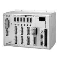
IAI X-SEL Operation Manual (566 pages)
P/Q/PCT/QCT Type
Brand:
IAI
| Category:
Controller
| Size: 10.89 MB
Table of Contents
Table of Contents
19
Introduction
23
Chapter 1 Safety Precautions
25
Part 1 Installation
25
Chapter 2 Warranty
26
Warranty Period
26
Scope of the Warranty
26
Honoring the Warranty
26
Limited Liability
26
Conditions of Conformance with Applicable Standards/Regulations, Etc., and Applications
27
Other Items Excluded from Warranty
27
Chapter 3 Installation Environment and Selection of Auxiliary Power Devices
28
Installation Environment
28
Heat Radiation and Installation
29
Selection of Auxiliary Power Devices
30
Noise Control Measures and Grounding
35
Chapter 4 Name and Function of each Part
38
Front View of Controller
38
Explanation of Codes Displayed on the Panel Window
51
Chapter 5 Specifications
55
Controller Specifications
55
External I/O Specifications
59
Power-Source Capacity and Heat Output
63
External Dimensions
67
Chapter 6 Safety Circuit
75
Items to Notes
75
Safety Circuit for P/PCT Type (Standard Specification) Controller
76
Safety Circuit for Q/QCT Type (Global Specification) Controller
78
Safety Circuit Timing Charts for Q/QCT Type SEL Controller
83
Chapter 7 System Setup
92
Connection Method of Controller and Actuator
92
I/O Connection Diagram
95
Multi-Point DIO Board
101
Chapter 8 How to Perform an Absolute Encoder Reset (Absolute Specification)
107
Single Axis, Orthogonal Axis and Rotating Axis
107
How to Perform Absolute Reset on ZR Unit (Absolute Type Only)
112
Chapter 9 Maintenance
127
Inspection Points
127
Spare Consumable Parts
127
Replacement Procedure for System-Memory Backup Battery
128
Replacement Procedure for Absolute-Data Backup Battery
131
Chapter 1 Operation
133
Starting a Program by Auto-Start Via Parameter Setting
134
Starting Via External Signal Selection
135
Drive-Source Recovery Request and Operation-Pause Reset Request
137
Part 2 Operation
133
Part 3 Controller Data Structure
138
Chapter 1 How to Save Data
139
Factory Settings: When the System-Memory Backup Battery Is Used
139
When the System-Memory Backup Battery Is Not Used
141
Points to Note
143
Chapter 2 XSEL Language Data
145
Values and Symbols Used in SEL Language
145
List of Values and Symbols Used
145
I/O Ports
146
Virtual I/O Ports
148
Flags
149
Variables
150
Tags
153
Subroutines
154
Character-String Literals
155
Symbols
155
Axis Specification
156
Command Part
158
Position Part
158
SEL Language Structure
159
Extension Condition
160
Chapter 1 List of SEL Language Command Codes
161
Commands
172
Part 4 Commands
161
Chapter 2 Explanation of Commands
173
Variable Assignment
173
Arithmetic Operation
175
Function Operation
178
Logical Operation
181
Comparison Operation
184
Timer
185
I/O, Flag Operation
188
Program Control
199
Task Management
202
Position Operation
207
Actuator Control Declaration
222
Actuator Control Command
242
Structural if
265
Structural DO
268
Multi-Branching
270
System Information Acquisition
274
Zone
277
1.18 Communication
281
String Operation
287
Palletizing-Related
296
Palletizing Calculation Command
310
Palletizing Movement Command
313
Building of Pseudo-Ladder Task
319
Extended Commands
321
Chapter 3 Key Characteristics of Actuator Control Commands and Points to Note
329
Continuous Movement Commands [PATH, CIR, ARC, PSPL, CIR2, ARC2, ARCD, ARCC, CIRS, ARCS]
329
PATH/PSPL Commands
331
CIR/ARC Commands
331
CIR2/ARC2/ARCD/ARCC Commands
331
Chapter 4 Palletizing Function
332
How to Use
332
Palletizing Setting
332
Palletizing Calculation
338
Palletizing Movement
339
Program Examples
341
Chapter 5 Pseudo-Ladder Task
349
Basic Frame
349
Ladder Statement Field
349
Points to Note
350
Program Example
351
Chapter 6 Application Program Examples
352
Operation by Jog Command [Doll-Picking Game Machine]
352
Operation by Point Movement Command [Riveting System]
355
Palletizing Operation [Palletizing System]
358
Chapter 1 Real-Time Multi-Tasking
361
SEL Language
361
Multi-Tasking
361
Difference from a Sequencer
363
Release of Emergency Stop
364
Program Switching
365
Part 5 Multi-Tasking
361
Chapter 2 Example of Building a System
366
Equipment
366
Operation
366
Overview of the Screw-Tightening System
367
Hardware
368
Software
370
Battery Backup Function
406
System-Memory Backup Battery
406
Absolute-Data Backup Battery
408
Expansion I/O Board (Optional)
410
Operation of High Speed Cartesian Robot (CT4)
411
Number of Regenerative Resistance Units to be Connected
412
(Applicable to both the Absolute Specification and Incremental Specification)
413
(When both the Master Axis and Slave Axis Are of the Absolute Specification)
413
Incremental Specification
413
Synchro Function
413
Absolute Reset of a Synchro Controller
414
Synchro Axes
414
Position Adjustment of Synchro-Axis Sliders
415
Special Absolute-Reset Procedure
415
Standard Absolute-Reset Procedure
420
Vibration Control Function
421
Multiple-Slider Near-Miss Detection (Collision Prevention) Function
426
General-Purpose RS232 (2-Channel RS232 Unit)
428
List of Parameters
435
I/O Parameters
436
Parameters Common to All Axes
464
Axis-Specific Parameters
468
Driver Card Parameters
475
Encoder Parameters
477
I/O Devices
478
Other Parameters
479
Pulse I/O Board Common Parameters
485
Pulse I/O Board Input Channel Parameters
486
Pulse I/O Board Output Channel Parameters
487
Manual Operation Types
488
Use Examples of Key Parameters
489
Combination Table of XSEL Linear/Rotary Control Parameters
496
Error Level Control
497
Error List
552
Troubleshooting of XSEL Controller
556
Trouble Report Sheet
562
Change History
563
IAI X-SEL Operation Manual (482 pages)
P/Q Type
Brand:
IAI
| Category:
Controller
| Size: 4.72 MB
Table of Contents
Table of Contents
20
Introduction
25
Chapter 1 Safety Precautions
27
Chapter 2 Warranty Period and Scope of Warranty
28
Warranty Period
28
Scope of Warranty
28
Scope of Service
28
Chapter 3 Installation Environment and Selection of Auxiliary Power Devices
29
Installation Environment
29
Heat Radiation and Installation
30
Selection of Auxiliary Power Devices
31
Noise Control Measures and Grounding
36
Chapter 4 Name and Function of each Part
39
Front View of Controller
39
Explanation of Codes Displayed on the Panel Window
52
Application
52
Core
53
Current Monitor and Variable Monitor
54
Chapter 5 Specifications
56
Controller Specifications
56
External I/O Specifications
60
NPN Specification
60
PNP Specification
62
Power-Source Capacity and Heat Output
64
External Dimensions
67
Chapter 6 Safety Circuit
75
Items to Notes
75
Safety Circuit for P Type (Standard Specification) Controller
76
Safety Circuit for Q Type (Global Specification) Controller
78
Chapter 7 System Setup
83
Connection Method of Controller and Actuator
83
I/O Connection Diagram
86
Multi-Point DIO Board
89
Chapter 8 How to Perform an Absolute Encoder Reset (Absolute Specification)
96
Preparation
96
Procedure
96
Chapter 9 Maintenance
101
Inspection Points
101
Spare Consumable Parts
101
Replacement Procedure for System-Memory Backup Battery
102
Replacement Procedure for Absolute-Data Backup Battery
105
Part 2 Operation
107
Chapter 1 Operation
107
Starting a Program by Auto-Start Via Parameter Setting
108
Starting Via External Signal Selection
109
Drive-Source Recovery Request and Operation-Pause Reset Request
111
Part 3 Controller Data Structure
112
Chapter 1 How to Save Data
113
Factory Settings: When the System-Memory Backup Battery Is Used
113
When the System-Memory Backup Battery Is Not Used
114
Points to Note
115
Chapter 2 X-SEL Language Data
116
List of Values and Symbols Used
116
Values and Symbols Used in SEL Language
116
I/O Ports
117
Virtual I/O Ports
118
Flags
120
Variables
121
Tags
124
Subroutines
125
Character-String Literals
126
Symbols
126
Axis Specification
127
Position Part
129
Command Part
130
SEL Language Structure
130
Extension Condition
131
Part 4 Commands
132
Chapter 1 List of SEL Language Command Codes
132
Chapter 2 Explanation of Commands
142
Commands
142
Variable Assignment
142
Arithmetic Operation
144
Function Operation
147
Logical Operation
150
Comparison Operation
153
Timer
154
I/O, Flag Operation
157
Program Control
168
Task Management
171
Position Operation
176
Actuator Control Declaration
191
Actuator Control Command
207
Structural if
230
Structural DO
233
Multi-Branching
235
System Information Acquisition
239
Zone
242
Communication
246
String Operation
252
Palletizing-Related
261
Palletizing Calculation Command
275
Palletizing Movement Command
278
Building of Pseudo-Ladder Task
284
Extended Commands
286
Chapter 3 Key Characteristics of Actuator Control Commands and Points to Note
292
Continuous Movement Commands [PATH, CIR, ARC, PSPL, CIR2, ARC2, ARCD, ARCC, CIRS, ARCS]
292
CIR/ARC Commands
294
CIR2/ARC2/ARCD/ARCC Commands
294
PATH/PSPL Commands
294
Chapter 4 Palletizing Function
295
How to Use
295
Palletizing Setting
295
Palletizing Calculation
301
Palletizing Movement
302
Program Examples
304
Chapter 5 Pseudo-Ladder Task
312
Basic Frame
312
Ladder Statement Field
313
Points to Note
313
Program Example
314
Chapter 6 Application Program Examples
315
Operation by Jog Command
315
Operation by Point Movement Command
318
Palletizing Operation
321
Part 5 Multi-Tasking
324
Chapter 1 Real-Time Multi-Tasking
324
SEL Language
324
Multi-Tasking
325
Difference from a Sequencer
326
Release of Emergency Stop
327
Program Switching
328
Chapter 2 Example of Building a System
329
Equipment
329
Operation
329
Overview of the Screw-Tightening System
330
Hardware
331
Software
333
Appendix
335
Actuator Specification List
335
How to Create a Program
341
Position Table
341
Programming Format
342
Positioning to Five Positions
343
How to Use TAG and GOTO
344
Moving Back and Forth between Two Points
345
Path Operation
346
Output Control During Path Movement
347
Circle/Arc Operation
348
Home Return Completion Output
349
Axis Movement by Input Waiting and Completion Output
350
Changing the Moving Speed
351
Changing the Speed During Operation
352
Local/Global Variables and Flags
353
How to Use Subroutines
354
Pausing the Operation
355
Canceling the Operation 1 (CANC)
356
Canceling the Operation 2 (STOP)
357
Movement by Position Number Specification
358
Movement by External Position Data Input
359
Outputting Coordinates
360
Conditional Jump
361
Waiting Multiple Inputs
362
How to Use Offset
363
Executing an Operation N Times
364
Constant-Pitch Feed
365
Jogging
366
Switching Programs
367
Aborting a Program
368
Battery Backup Function
369
System-Memory Backup Battery
369
Absolute-Data Backup Battery
371
Expansion I/O Board (Optional)
373
Number of Regenerative Resistors to be Connected
374
Synchro Function
375
Absolute Specification (When both the Master Axis and Slave Axis Are of the Absolute Specification)
375
Common Items (Applicable to both the Absolute Specification and Incremental Specification)
375
Incremental Specification
375
Absolute Reset of a Synchro Controller
376
Synchro Axes
376
Position Adjustment of Synchro-Axis Sliders
377
Special Absolute-Reset Procedure
377
Standard Absolute-Reset Procedure
380
Notes on Use of the Synchro Function
381
Multiple-Slider Near-Miss Detection (Collision Prevention) Function
382
General-Purpose RS232 (2-Channel RS232 Unit)
384
List of Parameters
392
I/O Parameters
393
Parameters Common to All Axes
406
Axis-Specific Parameters
409
Driver Card Parameters
414
Encoder Parameters
417
I/O Devices
418
Other Parameters
419
Manual Operation Types
425
Use Examples of Key Parameters
426
Combination Table of X-SEL Linear/Rotary Control Parameters
432
Error Level Control
433
Error List
435
Troubleshooting of X-SEL Controller
474
Trouble Report Sheet
481
Advertisement
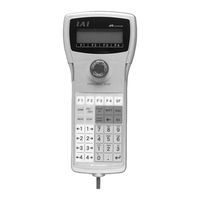
IAI X-SEL Operating Manual (135 pages)
Teaching Pendant
Brand:
IAI
| Category:
Controller
| Size: 4.15 MB
Table of Contents
Table of Contents
2
1 Forward
4
2 Before Use
4
3 Safety Precautions
5
4 Warranty Period and Scope of Warranty
6
5 Connection to Controller
7
6 Teaching Pendant Function and Specifications
11
Main Operation Keys and Functions
11
7 Mode Transition Diagram
14
8 How to Save Data
19
Set-Up at Shipment with System Memory Backup Battery
19
Set-Up at Shipment Without System Memory Backup Battery
20
Caution
21
9 Simple Operation Procedure
22
Creation of Position Data
23
Programming
32
Changing Application Program
40
10 Program Execution
45
Operation Confirmation
45
Setting of Brake Point
47
Monitor under Operation
47
11 Position Edit
50
MDI (Manual Direct Input)
50
Teach (Teaching)
51
Example of Teaching Input
62
Position Data: Copy or Move
67
Position Data: Clear
68
12 Program Edit
69
How to Input Program
69
Symbol Input During Program Edit
74
Single Line Comment Input
76
Program: Copy or Move
78
Program: Clear
79
Flash ROM Writing
81
13 Symbol Edit
82
Symbol Edit Items
82
Input Example: Symbolize Local Integer Variable
83
Symbol Edit Screen of each Items
87
Flash ROM Writing
91
14 Parameter Edit
92
Parameter Edit Items
92
Input Example: Edit Each-Axis Parameter
93
15 Monitor
96
Monitor Items
96
Input Port
97
Output Port
97
Global Flag
97
Global Variable
98
Axis Status
99
System Status
103
Error Detail Information
106
Version Information
107
16 Controller
109
Controller Items
109
Flash ROM Writing
110
Software Reset
111
Error Reset
111
Memory Clear
112
Re-Connection
112
Baud Rate Change
113
Safety Velocity
113
Driver Power Recovery Request
114
Action Pause Release Request
114
Driver Power Recovery Request (Rpwr) and Action Pause Release Request (Ract)
115
Absolute Reset
116
Procedures for Resetting Absolute-Battery Voltage-Down Warning Error
119
Supplement
121
Synchro Specification Absolute Reset
121
About Error Level Management
129
X-SEL Teaching Pendant Error List (Application Part)
130
X-SEL Teaching Pendant Error List (Core Part)
133
IAI X-SEL Operation Manual (149 pages)
profibus-dp
Brand:
IAI
| Category:
Controller
| Size: 2.1 MB
Table of Contents
Parameter no
14
Table of Contents
15
Parameter no
16
Parameter no
18
Parameter no
22
Parameter no
26
This Is a 9-Pin, Female D-Sub Connector Recommended by the Profibus-DP Standard en
48
IAI X-SEL Operation Manual (65 pages)
ethernet
Brand:
IAI
| Category:
Controller
| Size: 0.98 MB
Table of Contents
Table of Contents
5
Regulations and Standards Governing Industrial Robots
7
Safety Guide
7
Applicable Models of Iai’s Industrial Robots
9
Safety Precautions for Our Products
10
Alert Indication
15
1 Overview
17
Remote I/O Control
17
Message Communication
17
2 Interface Specifications
19
3 Interface Board
20
Name of each Part
20
Monitor LED Indications
21
Modbus/Tcp or TCP/IP Message Communication
21
Ethernet/Ip
21
4 Remote I/O (Modbus/Tcp Ethernet/Ip)
22
Setup of Ethernet Environment
22
Remote I/O Setup Procedure
23
Setup Procedure for Exception Status Support
27
Correspondence of Modbus/Tcp Address and X-SEL I/O
28
Little Endian Operation
29
Big Endian Operation
31
Installation to a Modbus/Tcp System
33
Installation to an Ethernet/Ip System
33
5 IAI Protocol B/TCP
34
Setup of Ethernet Environment
34
Ethernet Connection of X-SEL PC Software
38
Selecting the Controller
39
Changing the Connection Destination
39
Connection Destination Change
40
Items to Note
41
6 Transmission by SEL Program
42
Setup of Ethernet Environment
42
Ethernet Option SEL Commands
45
7 Common Items to Note (be Sure to Read this Section.)
53
Appendix: X-SEL (Cartesian/IX SCARA) Ethernet Option Parameters
53
X-SEL Ethernet Option Parameters
55
Advertisement
Related Products
IAI X-SEL QX
IAI X-SEL PX
IAI X-SEL-J*-1-CC0 series
IAI X-SEL-J*-2-CC0 series
IAI X-SEL-J*-3-CC0 series
IAI X-SEL-J*-4-CC0 series
IAI X-SEL Series
IAI acon
IAI ACON-C
IAI ACON-CA
IAI Categories
Controller
Digital Camera
Security Camera
Gateway
Robotics
More IAI Manuals
Login
Sign In
OR
Sign in with Facebook
Sign in with Google
Upload manual
Upload from disk
Upload from URL