IAI x-sel Operating Manual
Teaching pendant
Hide thumbs
Also See for x-sel:
- Operation manual (566 pages) ,
- Operation manual (65 pages) ,
- Operation manual (535 pages)
Table of Contents
Advertisement
Quick Links
Advertisement
Table of Contents

Related Manuals for IAI x-sel


Summary of Contents for IAI x-sel
- Page 1 X-SEL Teaching Pendant Operating Manual Ver. 7.0 IAI Corporation...
-
Page 2: Table Of Contents
Forward....................... Before Use ......................Safety Precautions ....................Warranty Period and Scope of Warranty............. Connection to Controller ..................Teaching Pendant Function and Specifications ..........6-1. Main Operation Keys and Functions ..............8 Mode Transition Diagram .................. How to Save Data ..................... 8-1. Set-up at Shipment with System Memory Backup Battery ........16 8-2. - Page 3 Absolute Reset ....................113 16-13. Procedures for Resetting Absolute-Battery Voltage-Down Warning Error..116 *Supplement ......................Synchro Specification Absolute Reset................118 About Error Level Management ..................126 X-SEL Teaching Pendant Error List (Application Part)............127 X-SEL Teaching Pendant Error List (Core Part) ...............130...
-
Page 4: Forward
1. Forward Thank you very much for purchasing our X-SEL Controller Teaching Pendant. Improper usage or mishandling may result in a product not only being unable to deliver full functions but also produce unexpected troubles or shorten the product’s life. Please read this Manual carefully, and operate the product properly by paying attention to its handling. -
Page 5: Safety Precautions
3. Safety Precautions (1) Use a genuine product specified by us for wiring between the actuator and X-SEL Controller. (2) Keep out of the operating range of a machine such as an actuator while it is operating or in a ready state (condition in which the controller’s power is ON). -
Page 6: Warranty Period And Scope Of Warranty
4. Warranty Period and Scope of Warranty The Teaching Pendant you purchased has been delivered upon completion of our strict shipping test. We shall warrantee this product as follows. 1. Warranty Period The warranty term shall be either of the following terms, whichever is reached first. ▪... -
Page 7: Connection To Controller
5. Connection to Controller Mode Switch M cable K (J) Type Controller... - Page 8 Emergency Stop Switch Enable Switch Teaching Pendant Type Selection Switch Mode Switch P Type Controller Caution ▪ Set the teaching pendant type selection switch to the right.
- Page 9 1. Connect actuators, I/O 24VDC power source, and system I/O to the controller first. Then connect the cable connector of the teaching pendant to the controller’s teaching connector when the main power supply of the controller is OFF. 2. After you flip the mode switch to MANU side, supply power to the controller. Teaching Pendant LCD Display Displays the version of the teaching pendant and...
- Page 10 Extra Caution When the X-SEL controller J/K type executes “OPEN 1” (channel 1 shared for the teaching pendant) within the SEL program in the MANU (manual) mode, the right of use of the serial port channel 1 is forcefully moved to the SEL program and communication with the teaching pendant is disconnected.
-
Page 11: Teaching Pendant Function And Specifications
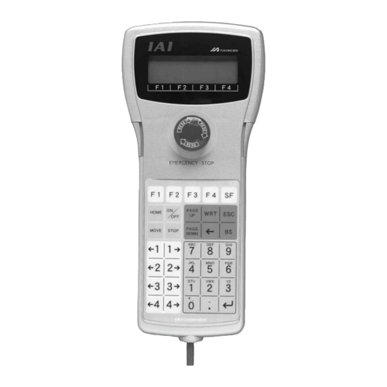
6. Teaching Pendant Function and Specifications Main Operation Keys and Functions 1. LCD Display 4 lines with 20 characters per line capacity display. Shows programs and motion status. 2. Emergency Stop Button Executes emergency stop. 3. Deadman Switch (Option) Before operating keys for Servo OFF → Servo ON, keep pressing both sides (ON) and operating keys. - Page 12 4. F1 F2 F3 F4 (Function keys) Correspond to each item in the LCD display (function key section). 5. SF key (Shift key) If there are more than 5 selectable functions (“→“ will be displayed at right side of the function key area), it will change the display items in the function key area.) 6.
- Page 13 11. ↵ key (Return key) Confirms the input data and moves the cursor position forward . 12. PAGE UP · PAGE DOWN key Increment or decrement edit and display item No. (Position No., Program No., Step No., etc.) 13. ON/OFF key Switches servo ON or OFF of axes.
-
Page 14: Mode Transition Diagram
7. Mode Transition Diagram Power ON Communications established Select position No. and Function key Function key Function key Function key press return Position data Mode input selection (Position) Manual input) (Velocity input) * After writing data with [WRT], move to the next position * When escaping the mode with [ESC], check whether to write to Flash ROM. - Page 15 Select the Select the step No. program No. and press return Function key and press retur Step data input (Program) (Modify) * After writing data with [WRT], move to the next step * Move to the symbol edit mode with “Sym” (Copy/Move) (Clear) Select the symbol type with the function key...
- Page 16 Function key (Monitor) (Input port) (Output port) (Global flag) Function key (Global (Integer variable) variable) (Real variable) (String variable) Function key (Current (Axis status) position) (Servo status) (Sensor input status) (Encoder status) (Axis-related error)
- Page 17 Function key (System (System status) mode) (System error) (System status 1) (System status 2) (System status 3) (System status 4) (Error list) Function key (Version) (CTL main) (Driver) (Teaching pendant) (P/Q type only) (Mount SIO) (P/Q type only) (P/Q type only) (Control constant)
- Page 18 * Displayed only when manual operation classification parameter=edit/start up selection (with password). * You will need to input the password to change setting. (PIO start (Refer to the Supplement and section 8 “Manual Operation” in the X-SEL Controller Instruction prohibit select) Manual.) ▪ Flow at Error Occurrence...
-
Page 19: How To Save Data
8. How to Save Data Since the X-SEL Controller adopts flash memory, there is a storage area by battery backup and a storage area by flash memory according to the data to be stored. In addition, even if data is transferred from the PC software or Teaching Pendant, the data is only to be written in memory as shown in the chart below and the data is erased by power-off or controller reset. -
Page 20: Set-Up At Shipment Without System Memory Backup Battery
Since the program, parameter, and symbol will be read from flash memory at restart time, the data in memory becomes the original data before editing unless the data is written in flash memory. The controller always operates according to the data in memory (within the dotted box) excluding parameters. -
Page 21: Caution
8-3. Caution Cautions in data transfer and flash writing Never shut OFF the main power while the data is transmitting and writing into flash. Data may be lost and controller may be rendered inoperable. Cautions in storing parameters in a file Encoder parameters are stored in EEPROM of the actuator’s encoder itself (not in EEPROM within the controller, which is different from the other parameter types). -
Page 22: Simple Operation Procedure
9. Simple Operation Procedure Here, the program and position data to draw a simple “pentagon” passing through the following 6 points (① and ⑥ are same position) by the actuator of 2 axes (X, Y) are created. Home Position Data (① to ⑥) -
Page 23: Creation Of Position Data
9-1. Creation of Position Data Input 6 points position data which can draw pentagon as the following position data list. Connect the teaching pendant to the controller and turn on MODE switch to MANU side. Supply the power to the controller. Display the version of the teaching pendant and move to the mode selection screen. - Page 24 Mode Selection Screen This is the basic screen for all operations. Press the F1 key (Edit). * If you make a wrong selection or input, press the ESC key and return to the previous screen. Then, you can continue operation. You can return to the basic screen by pressing the ESC key several times from any screen.
- Page 25 Position (Position Data) Edit Screen Press the F1 key (Mdi). Position No. Input Mode Position No. Axis No. displayed The cursor is placed at position No. First axis data If there is no data, x.xxx will be displayed. Press Second axis data the return key and place the cursor at first axis position data.
- Page 26 ① Data input for the first point Axis No. on the cursor location Input 0 (number) and press the return key, 0.000 will be displayed and then the axis No. changes to 2 and the cursor position moves to the second axis position data.
- Page 27 The cursor moves to the second axis position data. Input 100 and press return key. Transmit the data with the WRT key and move to position No. 3. ③ Data input for the third point Input 100 for the first axis position data and press the return key.
- Page 28 ④ Data input for the fourth point Input 100 for the first axis position data and press the return key. Input 0 for the second position data and press the return key. Transmit the data with the WRT key and move to position No.
- Page 29 Transmit the data with the WRT key and move to position No. 6. ⑥ Data input for the sixth point Input 0 for the first axis position data and press the return key. Input 50 for the second axis position data and press the return key.
- Page 30 Return to the position edit screen by pressing the ESC key. The edit mode screen will be appear by pressing the ESC key once more. The Flash ROM writing screen will be appear by pressing the ESC key again. To write the data to Flash ROM, press the F1 (Yes) key.
- Page 31 Go back to the edit screen by pressing the ESC key. That’s all for inputting basic position data.
-
Page 32: Programming
Here, make a program by changing the data of the position data created in section 9-1. Application Program List This is the X-SEL program that was created in this chapter. For the details of each command, please refer to the operating manual that comes with the controller. - Page 33 Select the F1 key (Edit) at the mode selection screen. Select the F2 key (Prog) at the Edit Mode screen. Select the F1 key (Mdfy) on the program edit and new creation screen. Program No. Step No. Change to the program No. input screen. The cursor is located at the program No.
- Page 34 The Cursor moves to the appropriate step No. Press the return key. Input commands. Commands are displayed in the function key area. How to search the command ① When the cursor is located at commands input locations, commands displayed alphabetical order by pressing SF key. The command which starts from G ②...
- Page 35 The cursor moves to operation 1. Input 11 and press the return key. When you redo an input Move the cursor where you want to redo an input by pressing the ← key and return key. Write over or delete with BS (backspace) key. Or redo from step No.
- Page 36 Here, input the velocity* as 100, and press the return key. * Check the maximum velocity listed in the catalogs. When velocity is input into position data, priority is given there. Transmit the data to the controller by pressing the WRT key.
- Page 37 Input 1 on position No. and press the return key. Transmit the data to the controller by pressing the WRT key. The cursor moves to step No.4. * If you change the screen with the PAGE UP · PAGE DOWN or ESC keys before transmitting the data, the input data will be invalid.
- Page 38 Transmit the data to the controller by pressing the WRT key. * If you change the screen with the PAGE UP · PAGE DOWN or ESC keys before transmitting the data, the input data will be invalid. Finish editing the program and write the data to Flash ROM.
- Page 39 Press the ESC key. To write the data to Flash ROM, press the F1 (Yes) key. If not, press the F2 (No) key. During Flash ROM writing, “Please Wait..” blinks. * Never shut off the power to the controller during Flash ROM writing. Flash ROM writing is complete.
-
Page 40: Changing Application Program
9-3. Changing Application Program Change the program you made in the previous section (9-2). Insert and delete the program step to allow the same action to be repeated. Change Insert “TAG 1” into step No.3, delete the line which displays “MOVL 6,” and write over “GOTO 1” replacing it with “EXIT.”... - Page 41 Select the F1 key (Mdfy) on the program edit and new creation screen. Change to the program edit mode screen. Press the return key once and position the cursor at the step Insert a 1 line step between step No. 2 and 3. Input 3 by pressing “3”...
- Page 42 Select the F4 key (TAG) and press the return key. Input 1 into operation 1 and press the return key. Transmit the data to the controller by pressing the WRT key. * If you change the screen with the PAGE UP · PAGE DOWN or ESC keys before transmitting the data, the input data will be invalid.
- Page 43 Press the F2 key (Del). Press the F2 key (Del) one more time. (If you wish to cancel deleting, press the ESC key.) Press the return key. Display “GOTO” by using the 9 key or SF (shift) key. Select the F3 key (GOTO) and press the return key.
- Page 44 Input the same value you input at “TAG” operation 1 on operation 1. Here, input 1 and press the return key. Transmit the data to the controller by pressing the WRT key. * If you change the screen with the PAGE UP · PAGE DOWN or ESC keys before transmitting the data, the input data will be invalid.
-
Page 45: Program Execution
10. Program Execution Execute the program made at the previous chapter. 10-1. Operation Confirmation Press the F2 (Play) key from the mode selection screen and move to the play mode screen. Play Mode Screen There are 3 kinds of items at the play mode screen: F1 (Run): Move to the program No. - Page 46 Move to the operation mode selection screen. Select step by step execution or the continuance operation. Operation Mode Selection Start the operation by Start the continuance pressing the F2 (Step) operation by pressing key. the F1 (Strt) key. Continuance Operation Mode Step Operation Mode Display the current executing program After...
-
Page 47: Setting Of Brake Point
10-2. Setting of Brake Point rake point can be set with the continuance operation. Press the F4 (Brk) key in the operation mode selection screen or the operation mode screen. Select the step No. to set brake point by pressing the Program No. - Page 48 (2) Local Flag This is the local flag On/OFF display. It can be switched ON/OFF. Press the F2 (LFlg) key on the operation mode screen. Mode Transition: The local flag where the cursor is located can be switched ON/OFF each time by pressing the F1 (0/1) key.
- Page 49 ③ Local String Mode Transition: The cursor is located in the data area (column). Input the ASCII code by pressing one of 10 keys and press return key to substitute letters. (Convert hexadecimal alphabet with (Alph/Num) key and then input substitution.) Move the cursor location with the return key and ←...
-
Page 50: Position Edit
11. Position Edit 11-1. Mdi (Manual Direct Input) The input value of the position data can be entered with the 10 numeric keys. For inputting input data for a coordinate by using the 10 numeric keys, please refer to “9. Simple Operation Procedures.”... -
Page 51: Teach (Teaching)
11-2. Teach (Teaching) Teaching is one way to input position data moving the actuator to an arbitrary position and getting that actuator’s current position as data. Methods for moving the actuators to a designated position are the jog, inching, and manual operation with a servo OFF status. - Page 52 (1) Teaching Screen There is the position No. selection screen and each-axis data input screen for the teaching screen. Execute teaching of all axes simultaneously (take in current position · clear) on the position No. selection screen. Execute teaching of each axis at each-axis data input screen.) ①...
- Page 53 ② Description of the function key Each-axis Data Input Screen F1(Disp): Switch the input data screen to the current position display. F2(Scan): Take the current position of the axis at which the cursor is located into the input screen. F3(Canc): Clear the input data. F4(Axis): Switch the 1st to 4th axes display screen to the 5th and 6th axes...
- Page 54 For incremental specification, it is required to execute homing after supplying power before you start teaching. Turn the servo On by pressing the ON/OFF key in the teaching screen condition. To confirm servo ON/OFF status, press the F1 (Disp) key. All axes start homing by pressing the HOME key.
- Page 55 (2) Movement of an actuator ① Jog Operation Turn the servo ON status by pressing the ON/OFF key in the teaching screen condition. To confirm the servo ON/OFF status, press the F1 (Disp) key to display the current position. Press the 1→, 2→, 3→, 4→, ←1, ←2, ←3, and ←4 keys to move the actuator to a designated position.
- Page 56 ② Inching Operation Set the inching distance. (the moving distance each Inching distance 0.1mm time pressing jog key.) Input the value on Dis (inching distance) at the jog velocity change screen and press the return key. Value input range is 0.001~1.000 (unit: mm). Return to the teaching screen with the ESC key and execute the inching operation.
- Page 57 (4) Transmit to the Controller Transmit the taken-in data to the controller. Press the WRT key in the teaching screen condition. Save the taken-in data to the controller memory. Position No. will be increased 1 by pressing the WRT key. You can only transmit 1 screen of data to the controller.
- Page 58 ② Moving Move the actuator to the location of the position data transmitted to the controller. Position No. to move Select position No. to move in the teaching screen condition. Press the ON/OFF key to turn the servo ON. To confirm the servo ON/OFF status, press the F1 (Disp) key.
- Page 59 ③ Continuous movement Move the actuator continuously to the location of the position data transmitted to the controller. Position No. you’d like to move first Select the position No. to move first in the teaching screen condition and press return key. Press the ON/OFF key to turn the servo ON.
- Page 60 (6) User-specified output port operation The output ports set for the parameter can be easily turned ON/OFF. Select UsrO among the function keys in a teaching screen condition. (A) User-specified output port status The conditions of user-specified output ports are displayed as “1” (=ON) and “0” (=OFF). (The conditions are displayed from the first specified port for the number of specified ports.) (B) Current position and servo ON/OFF...
- Page 61 ① Setting of user-specified output port parameters For the operation method for parameter setting, refer to “14. Parameter Edit.” The first port No. and the number of ports are set with the following parameters: ▪ Number of ports I/O parameter No. 74 “Qnt Prt Usr Out” (Number of output ports used by TP user [hand, etc.]) ▪...
-
Page 62: Example Of Teaching Input
11-3. Example of Teaching Input Entering the data into position No.10 using the jog and into position No.11 by manual operation with Servo OFF status. Select the F1 (Edit) key on the mode selection screen. Select the F1 (Posi) key. Select the F2 (Teac) key. - Page 63 Move the actuator to the designated position by pressing the jog keys, ←1, 1→, ←2, and 2→. Take in the current position data of the axis No. where the cursor is located by pressing the F2 (Scan ) key. Switch the display to the data input screen with the F1 (Disp) key.
- Page 64 Turn the servo OFF by pressing the ON/OFF key. F: Servo OFF Press the F1 (Disp) key to confirm the servo OFF N: Servo ON status. Move each axes to the designate position via manual mode. Note: Be sure to confirm the status is servo OFF and then execute operation.
- Page 65 Finish the position data input by teaching. Press the ESC key. Press the ESC key. Press the ESC key. Press the ESC key. To write the data to Flash ROM, press the F1 (Yes) key. If not, press the F2 (No) key.
- Page 66 During Flash ROM writing, “Please Wait..” blinks. * Never shut off the power to the controller during Flash ROM writing. Return to the edit screen with the ESC key.
-
Page 67: Position Data: Copy Or Move
11-4. Position Data: Copy or Move The following operating instructions are to copy or move the position data to another position No. Select F1 (Edit) key on the mode selection screen. Select the F1 (Posi) key. Select the F3 (Copy) key. Positions from which data is copied or moved First No. -
Page 68: Position Data: Clear
11-5. Position Data: Clear The following operating instructions are to clear the position data. Select the F1 (Edit) key on the mode selection screen. Select the F1 (Posi) key. Select the F4 (Clr) key. Position data to clear First No. Last No. -
Page 69: Program Edit
12. Program Edit 12-1. How to Input Program How to input Expansion Condition (E), Input Condition (N·Cnd), and Output (Pst) The sequence of program inputs for the teaching pendant is different from the program edit screen of the PC software. The sequence is as ①... - Page 70 Select the F1 (Edit) key on the mode selection screen. Select the F2 (Prog) key on the edit mode screen. Select the F1 key (Mdfy) on the program edit and new creation screen. Input the program No. by using the 10 keys and press the return key.
- Page 71 Input section of Cmnd Press the return key. Input section of Operand 1 Press the return key. Input section of Operand 2 Press the return key. Input section of Pst Press the return key. Input section of E Press the return key.
- Page 72 Input section of N·Cnd Input “601” by using the 10 keys and press the return key. Transmit the data of step No.1 to the controller by pressing the WRT key. Step No. moves to 2. * If you change the screen with the PAGE UP · PAGE DOWN or ESC keys before transmitting the data, the input data will be invalid.
- Page 73 Input section of Operand 2 (Indirect variable designation) Select the F3 (*) key first. Then input 201 by using the 10 keys and press the return key. (When you input a string at Operand 2, use the same format as Operand1.) Input section of Pst Input 900 by using the 10 keys and press the return key.
-
Page 74: Symbol Input During Program Edit
12-2. Symbol Input during Program Edit Symbol can be input when the cursor is located at Operand 1 · 2 (operation 1· 2), Pst (output) and Cnd (input condition) in the “Sym” state displayed in the function key area. Example: Input symbol of the program step below. - Page 75 The 10 keys become alphabet inputs. Input “TAIKIITI.” For the input procedure, please refer to the section “13. Symbol Edit.” Transmit the symbol data to the controller by pressing the WRT key. Return to the edit screen. The letter, S indicates symbol is used.
-
Page 76: Single Line Comment Input
12-3. Single Line Comment Input Turns a step from a program into a comment (invalid step) and you can input numbers, alphabets and signs (* · _). Mode Transition: Program No. return Move the cursor to the step No. for comment input. Press the F3 (Cmnt) key. - Page 77 Input numerical value Display “Num” in the F1 key area. Input the numerical value by using the 10 keys. The diagram on the left is an example for inputting “1.” After finishing the comment input, press the return key again. Transmit the input data to the controller by pressing the WRT key.
-
Page 78: Program: Copy Or Move
12-4. Program: Copy or Move The following operating instructions are to copy or move a program to another program No. Select the F1 (Edit) key on the mode selection screen. Select the F2 (Prog) key. Select the F2 (Copy) key. Input the program No. -
Page 79: Program: Clear
12-5. Program: Clear The following operating instructions are to clear a program. Select the F1 (Edit) key on the mode selection screen. Select the F2 (Prog) key. Select the F3 (Clr) key. Program No. to clear Input the program No. to clear by using the 10 keys and press the return key. - Page 80 Return to the previous screen with the ESC key. Furthermore, press the ESC key several times and return to the Flash ROM screen.
-
Page 81: Flash Rom Writing
12-6. Flash ROM Writing The edit data will be cleared by restoring the power and executing software reset, only if the program edit data was transmitted to the controller. To save the data after restoring the power and executing software reset, write the data to Flash ROM. -
Page 82: Symbol Edit
13. Symbol Edit Symbol (Names) can be applied to variables, input ports, flags, points, etc., in X-SEL controller. Select the F1 (Edit) key. Select the F3 (Sym) key. 13-1. Symbol Edit Items Symbolized items will be displayed in the function key area. -
Page 83: Input Example: Symbolize Local Integer Variable
13-2. Input Example: Symbolize Local Integer Variable Symbolize Variable No. 5 of program No. 3 to “Cnt5.” Press the F2 (Var) key. Mode Transition: Select an integer or real number. Press the F1 (Itg) key. (Int: Integer, Real: Real number) The cursor is located at program No. - Page 84 Press 5 several times to display “n.” Press the return key. Press the 1 (10 keys) several times to display “t.” Then press the return key. The F1 key area display changes to Num by pressing the F1 (Alph) key. It becomes a numerical input.
- Page 85 After determining symbol name, the cursor moves to the top letter. If it’s before determination, you can fix the letters one by one with the BS key. After determination, the name is corrected by overwriting all the characters. Transmit the symbol data to the controller by pressing the WRT key.
- Page 86 Return to the edit screen with the ESC key.
-
Page 87: Symbol Edit Screen Of Each Items
13-3. Symbol Edit Screen of Each Items (1) Constant Number Select the F1 (Cnst) key on the constant number symbol edit screen. Mode Transition: Selection of Integer Type · Real Number Type Constant Number Select an integer or real number. F1 (ltg): Integer F2 (Real): Real Number... - Page 88 (3) Program Select F3 (Prog) key on the symbol edit item screen. Mode Transition: Program No. Symbol Edit Screen Input alphabet and number. Input program No. by the PAGE UP · PAGE DOWN keys or 10 keys. (4) Position Select F4 (Posi) key on the symbol edit item screen. Mode Transition: Position No.
- Page 89 (6) Output Port Select F2 (Out) key on the symbol edit item screen. Mode Transition: Output Port No. Symbol Edit Screen Input alphabet and number. Input output port No. by the PAGE UP · PAGE DOWN keys or 10 keys. (7) Flag Select F3 (Flag) key on the symbol edit item screen.
- Page 90 (9) Tag Select F1 (Tag) key on the symbol edit item screen. Mode Transition: Tag No. Symbol Edit Screen Input program No. since tag No. is in the local area. Input alphabet and number. Input tag No. by the PAGE UP · PAGE DOWN keys or 10 keys.
-
Page 91: Flash Rom Writing
13-4 Flash ROM Writing The edit data will be the by restoring power and executing software reset, only if the symbol edit data was transmitted to the controller. To save the data after restoring the power and executing software reset, write the data to Flash ROM. -
Page 92: Parameter Edit
14. Parameter Edit You can change the parameters corresponding to your system. When you change the parameters by yourself, please note the parameter contents. Parameters will be valid by restoring the power or executing software reset after Flash ROM writing. Select the F1 (Edit) key on the mode selection screen. -
Page 93: Input Example: Edit Each-Axis Parameter
14-2. Input Example: Edit Each-Axis Parameter Set the soft limit + for the first and second axis of each-axis parameter No.7, 300mm and 200mm. Select the F3 (Axis) key on the screen of previous page, A. Mode Transition: The cursor is located at the parameter No. Input 7 by using the10 keys and press the return key. - Page 94 Input data of axis No. 2 The display screen moves to parameter No. 8. Axis No. 2 of parameter No. 7 is not edited yet, so, return to the parameter No. 7 edit screen with the PAGE DOWN key. Change the axis No. to 2 by using the F4 (Dev+) key.
- Page 95 To write the data to Flash ROM, press the F1 (Yes) key. If not, press the F2 (No) key. During Flash ROM writing, “Please Wait..” blinks. * Never shut off the power to the controller during Flash ROM writing. After writing the data to Flash ROM, the screen changes to the software reset screen.
-
Page 96: Monitor
15. Monitor Monitor each status, global variable, port status, etc. Select the F3 (Moni) key from The mode selection screen. 15-1. Monitor Items Monitor items will be displayed in the function key area. Each time by pressing the SF key, items will be shifted and displayed. Monitor Items Screen Input port Out:... -
Page 97: Input Port
15-2. Input Port Display the ON/OFF status of input port. Select the F1 (In) key on the monitor items screen. Mode Transition: 1: ON, 0: OFF Each time the PAGE UP · PAGE DOWN keys are pressed, the 20 port numbers are scrolled. 15-3. -
Page 98: Global Variable
15-5. Global Variable Displays the contents of global variable and global string. Also, a numeric value can be substituted for a global variable and letter string can be substituted for a global string. Select the F4 (GVar) key on the monitor items screen. Mode Transition: 3 kinds of global variables are displayed: Itg: Integer Type (No. -
Page 99: Axis Status
15-6. Axis Status Displays the current position of each axis, servo status, sensor status, etc. Select the F1 (ASts) key from the monitor items screen. Mode Transition: Posi: Current Position Srvo: Servo Status Snsr: Sensor Input Status Ecdr: Encoder Status ErrA: Axis Related Error (1) Current position... - Page 100 Over Push Limit Error (System Reservation) (System Reservation) (3) Sensor Input Status Mode Transition: Axis No. Axis No. Axis No. can be switched with the PAGE UP · PAGE DOWN keys. Creep Sensor Overrun Sensor Home Sensor (System Reservation)
- Page 101 (4) Encoder Status Mode Transition: Axis No. can be switched with the PAGE UP · PAGE Axis No. DOWN keys. Over Speed Full Absolute Status Count Error Counter Over Flow System Reservation Multi-rotation Error Battery Error Battery Alarm...
- Page 102 (5) Axis Related Error Mode Transition: Axis No. can be switched with the PAGE UP · PAGE Error Code Axis No. DOWN keys. Program No. Step No. Axis No. Position No. Information 1 Information 2 Information 3 Information 4...
-
Page 103: System Status
15-7. System Status Display system status. Select the F2 (SSts) key on the monitor items screen. Mode Transition: Mode: System Mode Err: System Error Sts1: System Status 1 Sts2: System Status 2 Sts3: System Status 3 Sts4: System Status 4 (1) System Mode Mode Transition: System Mode... - Page 104 (3) System Status 1 (4) System Status 2 Mode Transition: Mode Transition: Application Data Flash Operation Mode ROM Write Status SW Status Slave Parameter TP Enable Write Status SW Status Safety Gate Status Servo Interlock Status Emergency Stop I/O Interlock Status SW Status Power Abnormality Wait for Reset Status...
- Page 105 (5) System Status 3 (6) System Status 4 Mode Transition: Mode Transition: System status 4 is all reserved. (System Reservation) Power Down Status System Drive Status System Ready Status Function select flag request status (System Reservation) (System Reservation) (System Reservation) (System Reservation)
-
Page 106: Error Detail Information
15-8. Error Detail Information Displays the error detail information. Select the F3 (ErrL) key on the monitor items screen. Mode Transition: List No. Error Code Error Message Program No. Step No. Axis No. Position No. Information 1 Information 2 Information 3 Information 4... -
Page 107: Version Information
15-9. Version Information Displays version information. Select the F4 (Ver) key on the monitor items screen. Mode Transition: Main: Main Drv: Driver Teaching Pendant (1) Main Mode Transition: Controller Main Application Version Controller Main Core Version (2) Driver Mode Transition: Driver CPU Version (3) Teaching Pendant Mode Transition:... - Page 108 (4) Mount SIO (Controller P/Q type only) Mode Transition: Channel 1 Version Channel 2 Version * “Nonuse” is displayed for the channel with the I/O parameters No. 201 and No. 213 set to “Nonuse.” (5) FPGA Mode Transition: FPGA Version (HEX) Board ID (HEX) (6) Control Constant Table Management Information Mode Transition:...
-
Page 109: Controller
16. Controller How to execute operation related to the controller such as a software reset and an error reset. Select the F4 (Ctl) key on the mode selection screen. Controller operation items are displayed in the function key area. 16-1. Controller Items Each time by pressing the SF key, operation items will be shifted and displayed. -
Page 110: Flash Rom Writing
16-2. Flash ROM Writing After clearing the data from Flash ROM, write data which is saved in controller memory to Flash ROM. Select the F1(Flsh) key on the controller item screen. Mode Transition: To write the data to Flash ROM, press the F1 (Yes) key. -
Page 111: Software Reset
16-3. Software Reset Executes software reset of the controller. The data which is not written to Flash ROM will be cleared. Select the F2 (SRst) key on the controller item screen. Mode Transition: To execute a software reset, press the F1 (Yes) key. If not, press the F2 (No) key. -
Page 112: Memory Clear
16-5. Memory Clear Zero clears the global variable. Select the F4(MClr) key on the controller item screen. Mode Transition: Press the F1 (Gvar) key. To clear memory, press the F1 (Yes) key. If not, press the F2 (No) key. The screen returns to the previous screen. -
Page 113: Baud Rate Change
16-7. Baud Rate Change Changes the communication baud rate between the controller and the teaching pendant. Select the F2 (Baud) key on the controller item screen. Mode Transition: Input values corresponding to the baud rate by using the 10 keys and press the return key. 0: 9.6 1: 19.2 2: 38.4 [bps] To change the baud rate, press the F1 (OK) key. -
Page 114: Driver Power Recovery Request
16-9. Driver Power Recovery Request Requests to recover driver power to the controller. Select the F3 (RPwrl) key on the controller item screen. Mode Transition: To execute driver power recovery request, press the F1 (Yes) key. Return to the previous screen. If not, press the F2 (No) key. -
Page 115: Driver Power Recovery Request (Rpwr) And Action Pause Release Request (Ract)
16-11. Driver Power Recovery Request (RPwr) and Action Pause Release Request (Ract) (1) Driver Power Recovery Request ① How to execute Driver Power Recovery Request Execute Driver Power Recovery Request by any of the following: ▪ Set 1 in I/O parameter No.44 (Input Select Function 014 = Driver Power Cut-off Release Input) and ON edge input on Input port No.14. -
Page 116: Absolute Reset
16-12. Absolute Reset Executes absolute data reset. Select the F1 (RAbs) key on the controller item screen. Mode Transition: To execute absolute reset, press the F1 (Yes) key. If not, press the F2 (No) key. Return to the previous screen. Axis No. - Page 117 ③ Servo ON F1 (OK) key. ④ Homing F1 (OK) key. ⑤ Servo OFF You can execute absolute reset with the teaching pendant application version 1.02 or later and driver CPU ver 0.23 or later with servo ON status. Do not press the F1 (OK) key but press the PAGE UP key.
- Page 118 Return to the axis No. input screen. To execute absolute reset on other axes, input axis No. here and press the F1 (OK) key. Repeat ①~⑥. To finish absolute reset, press the ESC key. Move to the software reset screen. Press F1 (Yes) key to execute software reset.
-
Page 119: Procedures For Resetting Absolute-Battery Voltage-Down Warning Error
16-13. Procedures for Resetting Absolute-Battery Voltage-Down Warning Error When the absolute-encoder-battery voltage-down warning error (error code A03) occurs or a battery with no error occurring is replaced, the encoder error and software are reset. Homing in the absolute reset procedures does not have to be attempted again. Keep the controller’s main power ON until the following procedures have been completed: ①... - Page 120 ⑥ To continue the encoder error reset, press the F1 (OK) key. To cancel the encoder error reset, press the F2 (Canc) key. ⑦ Press the PAGE UP/PAGE DOWN key several times to display “7. Encoder Err Reset” screen. ⑧ To reset the encoder error, press the F1 (OK) key. (To cancel the encoder error reset, press the F2 (Canc) key.) ⑨...
-
Page 121: Supplement
Supplement Supplement: Synchro Specification Absolute Reset The following are descriptions about the absolute reset methods for synchro specification axes. The products ordered as the synchro specification are shipped after setting parameters to the synchro specification. However, change the parameters when executing an absolute reset. 1. - Page 122 Supplement 2. Location Adjustment of Synchro Axes Sliders Align the synchro axes sliders. (Physical parallel adjustment) (1) Adjust the relative locations between the sliders of the master and slave axes and connect them while the axes are not connected to the controller via cables (controller main power OFF).
- Page 123 Supplement Input 0 with the 10 keys and press the return key. Press the ESC key several times to move to the Flash ROM writing screen. Write the data to Flash ROM. Press the F1 (Yes) key. Execute restart (software reset). Press the F1 (Yes) key.
- Page 124 Supplement Exit from the absolute reset mode temporarily with the ESC key, without pressing the F1 (OK) key.
- Page 125 Supplement Press the F1 (RAbs) key to return to the absolute reset mode. ② Execute an absolute reset for the master axis according to the screen steps. Input the axis No. of the mater axis and press the return key. Press the F1 (OK) key.
- Page 126 Supplement Press the PAGE UP key to advance the screen, without pressing the F1 (OK) key. Press the F1 (OK) key. ③ Execute the “encoder multi-rotation data reset 1” for the slave axis again. Input the axis No. of the slave axis again and press the return key.
- Page 127 Supplement Return the slave-axis value for the “each-axis parameter No. 83 synchro slave axis coordinate initialization cancel” to the original value. Mode Transition: Slave axis Press the WRT key to transfer the data. Advance to the next parameter screen. Move to the Flash ROM writing screen with the ESC key.
- Page 128 Supplement (5) Set the preset home value to uniform the coordinate values of the master and slave axes. ① If the controller 7 segment display is “rdy” while the servo is OFF, read the displayed current positions of the master and slave axes. (If the error No.
-
Page 129: About Error Level Management
Supplement Write the data to Flash ROM. Press the F1 (Yes) key. Restart the controller. Press the F1 (Yes) key. (7) Display the current positions on the teaching screen. After turning the servo ON, execute action check by jogging. (Master axis operation) Mode Transition: To switch the current position screen to the input data screen, press the F3 (Disp) key. -
Page 130: X-Sel Teaching Pendant Error List (Application Part)
Supplement... - Page 131 Supplement...
- Page 132 Supplement...
-
Page 133: X-Sel Teaching Pendant Error List (Core Part)
Supplement... - Page 134 Supplement...
- Page 135 Ober der Röth 4, D-65824 Schwalbach am Taunus, Germany TEL 06196-88950 FAX 06196-889524 The information contained in this document is subject to change without notice for the purpose of product improvement. Copyright 2005. Mar. IAI Corporation. All rights reserved.
Need help?
Do you have a question about the x-sel and is the answer not in the manual?
Questions and answers