Table of Contents
Advertisement
XP3 SERIES PLC/HMI COMBINED UNIT MANUAL
XP3-16R/T/RT
XP3-18RT
XP3-18R
8 Points Input, 8 Points Transistor/Relay/Mixed Output,
Integrated OP330 and XC3 Series PLC
2 Expansion Boards
Integrated PLC & HMI
10 Points/Optical Couple Isolated
192x64 Pixels, 3.7 inch Screen
Integrated PLC & HMI
10 Points/Optical Couple Isolated
192x64 Pixels, 3.7 inch Screen
Doc Ref: LMAN007_R2V2
Advertisement
Table of Contents

Subscribe to Our Youtube Channel
Related Manuals for Xinje XP3-16R


Summary of Contents for Xinje XP3-16R
- Page 1 XP3 SERIES PLC/HMI COMBINED UNIT MANUAL XP3-16R/T/RT 8 Points Input, 8 Points Transistor/Relay/Mixed Output, Integrated OP330 and XC3 Series PLC 2 Expansion Boards XP3-18RT Integrated PLC & HMI 10 Points/Optical Couple Isolated 192x64 Pixels, 3.7 inch Screen XP3-18R Integrated PLC & HMI 10 Points/Optical Couple Isolated 192x64 Pixels, 3.7 inch Screen...
-
Page 2: Table Of Contents
XP3 PLC/HMI User Manual Index Page Chapter 1 Summary 1-1 Function 1-2 Specs 1-3 Component parts 1-4 Button functions 1-5 MP series COM ports 1-6 Dimensions and installation Chapter 2 Editing tool XP20 2-1 Summary 2-1-1 Edit tool installation/un-installation 2-1-2 Project 2-1-3 Screen content... -
Page 3: Function
1 Summary 1-1.Function 1-2.Specs 1-3.Component parts 1-4.Button functions 1-5.MP series COM ports 1-6.Dimensions and installation 1-1 Function The XP3 is an operator panel with touch function. Via text and indicator lamps, monitor or modify the value and status of PLC’s internal register and relay. -
Page 4: Specs
1-2 Specs 1. Specification 12V to 24V DC Input Voltage Below 4W (TYP2.0W) Power Below 20ms Momentary power allowance AC1000V -10mA for 1 minute Voltage Endurance DC500V - about 10MΩ Insulation impedance 2.Ambient Condition 0 to 50°C Operating temperature –10 to 60°C Storage temperature 20 to 85% (No dew) -
Page 5: Component Parts
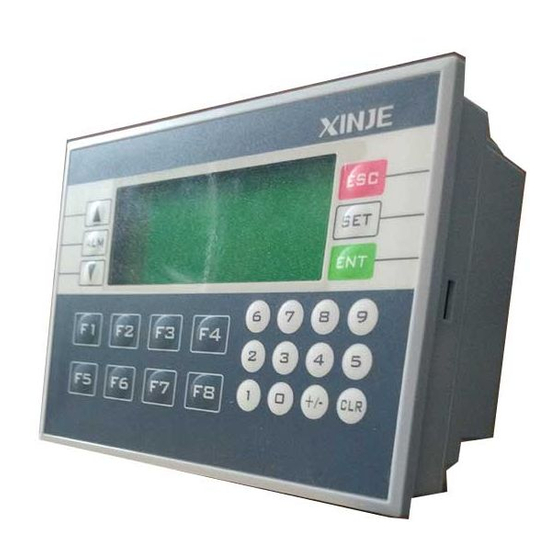
1-3 Component parts The direction keys select any screen and checks the screen status. Numb display Keypad Function keys COM port Label XP3 PLC/HMI Hardware Manual Page 5 of 42 LMAN007_R2V2 ... -
Page 6: Button Functions
1-4 Button functions Button Basic function Return to initial screen. The initial screen is appointed by the user when designing the screen (the default screen is number 1). (It can also be used as a function key) Page up Page down Select item to be modified Write the modified data to the register. -
Page 7: Mp Series Com Ports
1-5 MP series COM ports PORT1 download port [XP330] PIN ID Definition [XP330-S] PIN ID Definition Vacant Vacant DP-SYS-CAB connection DP210 Way PC9 Way XP3 PLC/HMI Hardware Manual Page 7 of 42 LMAN007_R2V2 ... -
Page 8: Dimensions And Installation
1-6 Dimensions and installation The cut-out size when installing: Note: 1. The fixing screws shouldn’t be too tight to avoid damaging the panel. 2. The four fixing screws should be under equal pressure. XP3 PLC/HMI Hardware Manual Page 8 of 42 LMAN007_R2V2 ... -
Page 9: Summary
2 Editing tool XP20 2-1.Summary 2-2.Edit environments 2-3.Component descriptions 2-4.Component properties 2-5.System window application 2-1 Summary 2-1-1 Edit tool installation/un-installation XP20 is the editing tool for XP series operator’s panels. It can run under Windows98/NT. 2-1-2 Project All the screens are compiled are saved in one project. -
Page 10: Flow Of Xp20
2-1-4 Flow of XP20 Basic programming flow of XP20: 2-2 Edit environments 2-2-1 Main screen After running XP20 edit tool, there will be a screen shown below in the centre of the computer. XP3 PLC/HMI Hardware Manual Page 10 of 42 LMAN007_R2V2 ... - Page 11 2-3 Add and delete PLC types In the following, we describe some keys and their functions Keys Functions Create a new project Open a saved project Save the editing project Cut the text in the display area Copy the text in the display area Paste the text in the display area Create a new screen, it’s function is the same with [New] Show the current screen’s attribution content...
- Page 12 The following are the 13 edit components. Component Function Text can input Chinese, English and some special signals. Register, place data monitor window or data setting window (The object is PLC data register) Indicate lamp, show PLC’s internal middle relay’s ON/OFF status. Function key, the 26 keys on XP330 can be all defined to be function keys.
-
Page 13: Component Properties
2-4 Component properties 2-4-1 Text Press the key, there will be a rectangle moving with the mouse. Confirm were to place it via the left-click on the mouse, right-click on the mouse to cancel. After you confirm, there will be a text “Message”... -
Page 14: True Type Text
2-4-2 True type text Press key, there will be a rectangle frame moving with your mouse. Confirm with your mouse’s lef-click, cancel with your mouse’s right-click. After your confirmation, there will be a message in the display area. Meanwhile, in the attribution area, display this text’s property. This component is similar with “Text”. -
Page 15: Dynamic Text
2-4-3 Dynamic text Click key, there will be a dashed frame moving with the mouse. Left-click the mouse to confirm (right-click to cancel). After your confirmation, there will be a “Dynamic Message” in the display area; meanwhile, its property will be shown in the property area. This icon is similar with “Text”, the difference is: Dynamic text’s content is connected with a register. -
Page 16: Dynamic True Type Text
2-4-4 Dynamic true type text Press key, add a dynamic true type text. There will be a defaulted “Dynamic Text” in the display area. Meanwhile, in the property area its property will be shown. Dynamic True Type Text is similar with Dynamic Text, the difference is: Dynamic True Type Text can change the font and display area while Dynamic Text cannot. -
Page 17: Lamp
2-4-5 Lamp Press key and place it in the display area. In the property area, you will see “Coil” and “Display”. The lamp is used frequently in the project; it can be used as status indication, alarm indication, or message indication etc. ... -
Page 18: Bar
2-4-6 Bar Click key and place it in the display area. The bar diagram is used to display directly analogue parameters, such as level pressure liquid level, etc. Its height, width and direction can be assigned freely. Range: The values determines the bar diagram’s width and height. - Page 19 2-4-7 Text Click key and place it in the display area. In a control system, the data operation is necessary. So this “Register” places a key role in the control system. Register: Register number: Set this register’s number. Take D0 as the example, the panel can directly monitor the changing of value in D0.
- Page 20 Note: When activating the register’s “Set”, it means this component has not only a monitor function but also a set function. 2-4-8 Text Click key and place it in the display area. Set its property in the property area. In industrial control, some parameters change slowly.
-
Page 21: Trend
Display: Full Value: The register’s corresponding value with the trend diagram 100% scale display. Zero value: The register’s corresponding value with the trend diagrams 0% scale display. Sample data (point number): From left to right, all the sample points that the whole trend diagram has. - Page 22 Hand: Display the hand diagram or not, the defaulted format is display. Disappear: Display this key or not. When choosing this key, the key’s function is the same, just not displayed in the screen. Encrypt: Need to input password or not. If choosing this item, you should input the password before you execute the set functions.
-
Page 23: Picture
Set Data function: Function: If you choose “Set Data” item, the property will area also change. Register: PLC station: The address of device connected with the panel. Register number: The sequence register number of data, which needs to be set. -
Page 24: Touch
Note: Use tools to edit the picture ensuring the proper size and contrast, and then add to the project screen. Normally, to OP series operate panel, the size is not larger than 180×60 pixels. Regarding LOGO pictures, the size is not larger than 35×35 pixels. ... -
Page 25: System Windows Application
2-5 System window application For XP series operators panel’s description, please refer to the manual XP series operator panel user manual. Here we mainly describe XP330. Select model: When creating a new project, you should choose a model, here we choose XP330 (XMP) as our model. - Page 26 Create a new screen To open: choose Menu Tool New or directly choose “New” or click in the tool bar. Method: each screen corresponds with a screen number, it can only be changed when the screen is created.
- Page 27 Create a new screen Alarm list: The alarm list plays a great role in the project. XP20 software integrates to XP series abnormal alarm system. To Open: Choose Menu Tool Alarm List; or directly choose in the tool bar.
- Page 28 Select “Interactive Control” or “Peripheral Control”, these two items will display brightly, it means they can be modified! Via modify register No., modify the corresponding register (If you choose PLC type as XINJE XC series, the defaulted register number is D0. ...
- Page 29 Use Data/Time Module: Corresponding D18 register. I.e., the panel’s real-time clock information is written into 6 continual register areas from D18 register. Set General Function Key To open: Choose “Menu-Tool”—“Set General Function Key”; or click icon directly. Method: In the defaulted condition, all the function keys could be defined separately.
-
Page 30: Application Flow
3 Application of P20 edit tool 3-1.Application flow 3-1 Application flow 3-1-1 Create a new project XP3 PLC/HMI Hardware Manual Page 30 of 42 LMAN007_R2V2 ... -
Page 31: Add Screens
PLC type compatible Listed below are some devices, which are supported by XP330. The XP330 can support most PLC’s, some single-chip devices, self-defined models and special function modules etc. XINJE XC Delta DVP Mitsubishi FX Facon MU/MA Koyo SG... -
Page 32: Edit Screens
3-1-3 Edit the screens “Edit screen” is very important in a project design: 3-1-4 Sett system parameters 1. Set the master screen number as ‘1’, i.e. set screen1 as the start screen. 2. If password is not necessary in the project, then set password as 0. 3. -
Page 33: System Passwords
3-1-5 System passwords 1. System password set the different operating limitation for different operator. Only after you open the password could you use some protected operations. 2. After setting function keys and touch keys in the screen, in the function key’s property frame, choose “Screen Jump”... - Page 34 Note: When downloading please don’t cut the power to the panel. Or a system malfunction will occur. If this condition occurs, please connect and download again 4 Using XP200 Edit tool XP3 PLC/HMI Hardware Manual Page 34 of 42 LMAN007_R2V2 ...
-
Page 35: Application Of Automatic Control
4-1.Application of automatic control 4-1 Application of automatic control 4-1-1 Add and set screen properties To modify screen 1 property: Double click the screen 1 in screen manager’s area. In the pop up dialog box, add screen description “Master Control”. Click key, add another four screens, and add screen description one by one: “Monitor”, “Parameter”, “Manual”... -
Page 36: Edit Monitor Screen
Set each touch key’s function and parameter: Manual Function: Screen jump; jump to screen 5 Automatic Function: Screen jump; jump to screen 4 Monitor Function: Screen jump; jump to screen 2 Parameter Function: Screen jump; jump to screen 3 3. - Page 37 Set the left elements: Add seven in the screen. Set the font and content, the content is “Status Indication”. Set the left six texts’ property: The content is: “Power”, “Run”, “Light”, “Auto Wind”, “Up”, “Down”. Modify the font and choose “Underline”. Place in the proper position. ...
- Page 38 3. Finish editing [Monitor] screen. XP3 PLC/HMI Hardware Manual Page 38 of 42 LMAN007_R2V2 ...
-
Page 39: Edit Parameter Screen
4-1-3 Edit parameter screen Screen Elements: Title Four text description Four unit description Four data setting units and one screen jump key 1. First, design the title Add one in the screen, modify the content as “Parameter”, choose “Inverse”, and set the font. -
Page 40: Edit Automatic Screen
4-1-4 Edit automatic screen Screen Element one title two function keys two-screen jump keys 1. First, set the title Add an icon in the screen, modify the content as “Automatic”, and choose “Inverse”; set the font. Drag this title to the proper position; please refer to the following diagram: 2. -
Page 41: Edit Manual Screen
4-1-5 Edit manual screen Screen Elements, one title, two function keys, and two screen jump keys 1. First, design the title Add one icon in the screen, modify the content as “Manual”, choose “Inverse”, and set the font. ... - Page 42 XINJE IS A REGISTERED TRADEMARK OF XINJE ELECTRICAL CO.LTD. REPLICATION OF THE INFORMATION CONTAINED WITHIN THIS DOCUMENT WITHOUT PRIOR NOTIFICATION AND AGREEMENT IS PROHIBITED. For help and support regarding your XINJE products visit the online Support Centre or contact us on: support@listo-ltd.com. www.listo-ltd.com www.xinje-support-centre-listo.com...
- Page 43 Contact us Listo Ltd. 25B Antrim Business Park Enkalon Industrial Estate Antrim Co.Antrim Northern Ireland BT41 4LD +44 (0)28 944 64968 info@listo-ltd.com www.xinje-support-centre-listo.com UK & Ireland Distributors for...
Need help?
Do you have a question about the XP3-16R and is the answer not in the manual?
Questions and answers