Grundfos DME 2 Product Manual
Dme series;
dms series.
digital dosing
Hide thumbs
Also See for DME 2:
- Installation and operating instructions manual (298 pages) ,
- Installation and operating instructions manual (92 pages)

Related Manuals for Grundfos DME 2


Summary of Contents for Grundfos DME 2
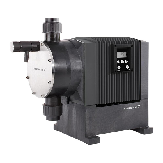
- Page 1 GRUNDFOS PRODUCT GUIDE CALL TOLL FREE 877-742-2878 FOR SALES AND SUPPORT. CLICK HERE TO RETURN TO WEBSITE. DME and DMS Digital Dosing...
-
Page 2: Table Of Contents
Control panel Menu Operating modes Dosing monitoring Control panel lock Wiring diagram, DME 2 to 48 and DMS-A (AR) Wiring diagram, DME (60 to 940) Construction Sectional drawing, DME (2 to 48) Material specification Sectional drawing, DME (60 to 940) -
Page 3: General Data
General data Performance range, DME [psi] [bar] DME 2-18 DME 8-10 DME 60-10 DME 375-10 12-6 19-6 DME 150-4 DME 940-4 DME 48-3 18.5 48 60 Q [l/h] 5 6 7 8 10 10 30 40 50 60 80 100... -
Page 4: Digital Dosing
Digital Dosing represents state-of-the-art technology. is working precisely, irrespective of the power supply This patented Grundfos solution sets new standards, (100-240 V; 50-60 Hz). including new principles and methods. The DMS version with synchronous motor and a turn-... -
Page 5: Type Key
Codes Example A - PP / E / C - 2 - 1 Example DME 2 - 18 - A - PP / E / C - F - 2 1 RR B Control variant Type range AG A + Genibus... -
Page 6: Functions
Functions DME and DMS Overview of functions 2 to 48 60 to 940 AR 60 to 940 B variant A variant B variant D Capacity control, see page 8 Internal stroke frequency control Internal stroke speed control Control panel, see page 10 Capacity setting in liters, milliliters or US gallons Display with background light... -
Page 7: Capacity Range
Functions DME and DMS Capacity range [psi] [bar] DMS, DME DME 2-18 DME 8-10 DME 60-10 DME 375-10 DMS 2-11 12-6 19-6 DME 150-4 DME 940-4 12-3 DME 48-3 12 12 18.5 48 60 Q [l/h] 5 6 7 8 10 10... -
Page 8: Capacity Control, Dme
• Easier dosing of highly viscous and gas-containing liquids. • A capacity range of 1:1000 (DME 2 to 48) for each pump size. The optimum dosing control shown below takes place in any operating mode. -
Page 9: Capacity Control, Dms
Functions Capacity control, DMS The electronically controlled synchronous motor of the • A capacity range of 1:100 for each pump size. DMS offers similar advantages of the DME pumps. As • Reduction of pressure surges, preventing mechani- shown in the figure below, the suction and discharge cal stress on diaphragm, tubes, connections and stroke speeds are constant while the stroke frequency other dosing parts exposed to leakage and wear. -
Page 10: Control Panel
Functions DME and DMS Control panel Indicator lights and alarm output (DME 2 to 48, DMS) The green and red indicator lights on the pump indicate operation or fault. Navigation/ LCD Display settings settings In control variant AR, the pump can activate an external ml/h alarm signal by means of a built-in alarm relay. - Page 11 Pump running Requires activation of the dosing monitoring function and connection indication to a dosing monitor. NC NO C Please contact a Grundfos service centre. Normal Set to stop Flashing Alarms can be reset after fault conditions are back to normal.
-
Page 12: Menu
Functions DME and DMS Menu The DME and DMS dosing pumps feature a user- friendly menu which is activated by pressing the button. During start-up, all texts will appear in the English language, but other languages can be selected (see page 16). The example shown below applies only to DME 60 to 940 pumps. -
Page 13: Operating Modes
Functions DME and DMS Operating modes Setting range, DME: DME 2-18: 0.000023 ml/pulse - 5.0 ml/pulse Manual control DME 8-10: 0.000069 ml/pulse - 15.0 ml/pulse DME 12-6: 0.000111 ml/pulse - 24.0 ml/pulse The pump is dosing constantly according to the quantity DME 19-6: 0.000204 ml/pulse -... - Page 14 Setting range (applies to DME only) Applies to DME Timer-based and pulse-based batch control 0.23 ml/batch 5 l/batch DME 2: The pump is dosing the set quantity in batches at 0.00006 G/batch 1.32 G/batch maximum capacity or the set capacity limitation.
- Page 15 Functions DME and DMS Anti-cavitation (60 to 940) The pump features an anti-cavitation function. When this function is selected, the pump extends and smoothes its suction stroke, resulting in softer priming. The anti-cavitation function is used: • when pumping liquids of high viscosity, •...
- Page 16 These modules enable remote monitoring and setting via the fieldbus system. All DME features are available via bus communication. The PROFIBUS GDS-file can be downloaded from www.grundfos.com/dosing. Diaphragm leakage sensor (DME 60 to 940) The pump can be fitted with a leak sensor that connects Vent valve to the drain hole of the pump head.
-
Page 17: Dosing Monitoring
Functions DME and DMS Dosing monitoring Applies to all DME 2 to 48 and DMS AR Dosing stoke measured Dosing stoke measured Dosing stoke measured Monitor mounted on suction side Monitor mounted on discharge side Monitor mounted in dosing tube. -
Page 18: Control Panel Lock
Functions DME and DMS • In pulse mode, set the quantity to be dosed in ml/ It is possible to add a self-acting solution for liquids that cause gas accumulation by using an automatic vent pulse. The actual capacity is indicated in liters per valve. -
Page 19: Wiring Diagram, Dme 2 To 48 And Dms-A (Ar)
Functions DME and DMS Wiring diagram, DME 2 to 48 and DMS-A (AR) See pages 30 and 32 for input/output data. "NO" black "NC" blue "COM" brown Control cable Level cable Product no.: Product no.: 2 m cable: 96440447 2 m cable: 96440450... -
Page 20: Wiring Diagram, Dme (60 To 940)
Functions DME and DMS Wiring diagram, DME (60 to 940) Relay cable Stop dosing cable Level cable Analog/Pulse/Leakage cable Product no.: Product no.: Product no.: Product no.: 2 m cable: 96534214 2 m cable: 96527109 2 m cable: 96440450 2 m cable: 96440447 5 m cable: 96534215 5 m cable: 96527111 5 m cable: 96440451... - Page 21 Functions DME and DMS Cable 3: Stop dosing input and dosing monitor or dosing output Number/color 1/brown 2/white 3/blue 4/black 5/grey Function Stop input Stop input potential-free potential-free Dosing monitor potential-free potential-free Dosing monitor Dosing output Open collector (pump running) (NPN) Open collector (NPN) can be used for a relay or a lamp.
-
Page 22: Construction
Construction Sectional drawing, DME (2 to 48) 1 16 10 11 12 20 19 Construction Material specification The DME pump is a motor-driven diaphragm dosing Pos. Description Material options pump consisting of the following main parts: Backplate 20% glass-filled PP Diaphragm Textile-reinforced EPDM, PTFE-coated Dosing head: Designed with a minimum of clearance... -
Page 23: Sectional Drawing, Dme (60 To 940)
Construction Sectional drawing, DME (60 to 940) Material specification Valve seat PP/PVDF/SS Ceramic/Glass/SS/ Valve ball Hastelloy C Pos. Description Material options Valve casing PP/PVDF/SS Backplate 20% glass-filled PP Spring DIN 17223 TYPE C Spring Hastelloy C Cabinet 20% glass-filled PP O-ring EPDM/FKM Origo sensor... -
Page 24: Sectional Drawing, Dms
Construction Sectional drawing, DMS 1 16 10 11 12 20 19 22 Construction Material specification The DMS pump is a motor-driven diaphragm dosing Pos. Description Material options pump consisting of the following main parts: Backplate 20% glass-filled PP Diaphragm Textile-reinforced EPDM, PTFE-coated Dosing head: Designed with a minimum of clearance Valve assembly Contains items 4 to 8... -
Page 25: Performance Curves
Performance curves DME 2-18 DME 19-6 [psi] [bar] [psi] [bar] Q [l/h] 20 Q [l/h] Q [US GPH] Q [US GPH] DME 8-10 DME 48-3 [psi] [bar] [psi] [bar] Q [l/h] 50 Q [l/h] Q [US GPH] 12 Q [US GPH]... - Page 26 Performance curves DME 60-10 DME 375-10 [psi] [bar] [psi] [bar] 150 200 250 300 350 Q [l/h] Q [l/h] Q [US GPH] Q [US GPH] DME 150-4 DME 940-4 [psi] [bar] [psi] [bar] 100 120 140 Q [l/h] 0 100 200 300 400 500 600 700 800 900 Q [l/h] Q [US GPH] Q [US GPH]...
- Page 27 Performance curves DMS 2-11 DMS 8-5 [psi] [bar] [psi] [bar] 2.5 Q [l/h] Q [l/h] 0.6Q [US GPH] Q [US GPH] DMS 4-7 DMS 12-3 [psi] [bar] [psi] [bar] Q [l/h] 4.0 Q [l/h] Q [US GPH] Q [US GPH]...
-
Page 28: Dimensions
Dimensions DME and DMS Front-fitted control panel DME 2 to 48, DMS 4 3/8 ml/h 100% 1.97 3 7/8 Side-fitted control panel DME 2 to 48, DMS 5.12 4 3/8 ml/h 100% 3 7/8 1.97 Dimensions are in inches (mm) -
Page 29: Dme (60 To 940)
Dimensions DME and DMS DME (60 to 940) Dimensions are in inches (mm) DME 60 DME 150 DME 375 DME 940 6.93 (176) 6.93 (176) 9.37 (238) 9.37 (238) (198) (198) 8.58 (218) 8.58 (218) 13.03 (331) 13.58 (345) 18.54 (471) 19.53 (496... -
Page 30: Technical Data
Technical data DME (2 to 48) Pump DME 2 DME 8 DME 12 DME 19 DME 48 [l/h] 18.5 Maximum capacity without anti-cavitation [GPH] 0.66 1.98 3.17 4.88 12.68 [l/h] 14.5 Maximum capacity with anti-cavitation [GPH] 0.49 1.48 2.78 3.66 9.51... -
Page 31: Dme (60 To 940)
Technical data DME (60 to 940) Pump DME 60 DME 150 DME 375 DME 940 Maximum capacity 15.9, (60) 39.6, (150) 99.1, (375) 248.3, (940) [GPH (l/h)] [GPH 0.0198 0.0495 0.1238 0.3104 Minimum capacity (ml/h)] (75) (187,5) (468.75) (1175) Maximum capacity with anti-cavitation 75% [l/h] 11.9, (45) 29.6, (112) 74.2, (281) 186.2, (705) [GPH (l/h)]... -
Page 32: Dms
Technical data Pump DMS 2 DMS 4 DMS 8 DMS 12 [l/h] DMS-A and AR, B [gph] 0.66 1.05 1.98 3.17 [l/h] 3.3 ± 20% 5.7 ±18% 8.7 ± 8% 13.7 ± 6% DMS-D Maximum capacity (50 Hz) [GPH] 0.87 ± 20% 1.5 ±18% 2.3 ±... -
Page 33: Pump Selection
Product Ship Weight Pump Head Material Model Variant Material Discharge [in] Material Position Number [lbs] DME 2-18 0.66 GPH (2.5 l/h) up to 261 psi (18 bar) Front DME2-18 A-PP/E/C-F-21RRB 96470128 EPDM Side DME2-18 A-PP/E/C-S-21RRB 96470129 Front DME2-18 A-PP/V/C-F-21RRB 96470130... -
Page 34: Dme 19 To 48 - Standard Range
Pump selection DME and DMS DME 19 to 48 - standard range DME, 50/60 Hz, 100-240V with US 120V Plug Connections, Ship Pump Head Control Valve Ball Gasket Control Product Suction/ Discharge Model Weight Material Variant Material Material Position Number [in] [lbs] DME 19-6 4.88 GPH (18.5 l/h) up to 87 psi (6 bar) -
Page 35: Dme 60 To 150 - Standard Range
Pump selection DME and DMS DME 60 to 150 - standard range DME, 50/60 Hz, 100-240V with US 120V Plug Connections, Ship Pump Head Control Valve Ball Gasket Control Product Suction/ Model Weight Material Variant Material Material Position Number Discharge [lbs] DME 60-10 15.85 GPH (60 l/h) up to 145 psi (10 bar) Front... -
Page 36: Dme 375 To 940 - Standard Range
Pump selection DME and DMS DME 375 to 940 - standard range DME, 50/60 Hz, 100-240V with US 120V Plug Connections, Ship Pump Head Control Valve Ball Gasket Control Product Suction/ Model Weight Material Variant Material Material Position Number Discharge [lbs] DME 375-10 99.06 GPH (375 l/h) up to 145 psi (10 bar) Front... -
Page 37: Dms 2 To 4 - Standard Range
Pump selection DME and DMS DMS 2 to 4 - standard range DMS, 60 Hz, 120V with US 120V Plug Connections, Ship Pump Head Control Valve Ball Gasket Control Product Suction/Discharge Model Weight Material Variant Material Material Position Number [in] [lbs] DMS 2-11 0.66 GPH (2.5 l/h) up to 160 psi (11 bar) Front... -
Page 38: Dms 8 To 12 - Standard Range
Pump selection DME and DMS DMS 8 to 12 - standard range DMS, 60 Hz, 120V with US 120V Plug Connections, Ship Pump Head Control Valve Ball Gasket Control Material Suction/ Discharge Model Weight Material Variant Material Material Position Number [in] [lbs] DMS 8-5 1.98 GPH (7.5 l/h) up to 78.3 psi (5.4 bar) -
Page 39: Non-Standard Options
Profibus GENibus DME 2 to 48 PTFE check valves with Ceramic or PTFE DME 2 to 48, DMS balls PTFE balls in PP or PVDF check valves DME 2 to 48, DMS SS balls in PP or PVDF check valves DME, DMS 1/2"... -
Page 40: Pumped Liquids
Pumped liquids DME and DMS List of pumped liquids The data shown are based upon information from various sources available, but many factors (purity, The resistance table below is intended as a general temperature, abrasive particles, etc.) may affect the guide for material resistance (at room temperature), chemical resistance of a given material. - Page 41 Accessories Overview Accessories Grundfos offers a comprehensive range of accessories covering every need when dosing with Grundfos dosing pumps. Overview Back-pressure or relief Injection valve See page 57 See page 47 Automatic vent valve Pulsation dampener See page 60 See page 61...
- Page 42 Ball Gasket Suction Vent 1/4" 1/4" 96480670 EPDM 3/8" 1/4" 96479881 1/2" 1/4" 96479947 Ceramic 1/4" 1/4" 96480674 DME 2 to 48 3/8" 1/4" 96479898 1/2" 1/4" 96479948 1/4" 1/4" 96480675 PVDF Ceramic 3/8" 1/4" 96479899 1/2" 1/4" 96479949 Inner/Outer tubing diameter sizes Tube size 1/4"...
- Page 43 Control cable with plug 96527111 Relay cable with plug 96534214 Alarm Relay Cable* Relay cable with plug 96534215 Only DME 60 to 940 Note - DME 2 to 48 and DMS AR versions have alarm relay cable hard-wired to pump.
- Page 44 Accessories Diaphragm leakage sensor Diaphragm leakage sensor (DME 60 to 940) Optoelectronic leakage sensor to be inserted in the drain hole behind the diaphragm for sensing diaphragm breakage or leakage. The sensor unit consists of: • Transmitter receiver • Holder for fitting sensor in the backplate •...
- Page 45 Accessories Tubing Tubing Tubing in various materials, sizes and lengths. Inner/outer diameter Maximum pressure Length Product Material (in) (psi) (ft) Number 0.17 x 1/4 91127749 91127750 91127825 1/4 x 3/8 91127751 ETFE 91127753 91127826 3/8 x 1/2 91127752...
- Page 46 Accessories Foot valve Foot valve Foot valve complete with non-return valve, strainer and tube or pipe connection. Dimensions DN 4, DN 8 DN 6, DN 10, DN 15, DN 20, DN 25 Tubing/non-return valve Hose clamp Pipe cementing Non-return valve Max flow rate Materials Connection...
- Page 47 Accessories Injection valve Injection valve Injection valve complete with spring-loaded non-return valve, injection pipe and tube or pipe connection. Spring material: Hastelloy Opening pressure: DN 4, DN 8: 10 psi (0.7 bar) DN 6, DN 10, DN 15, DN 25: 16 psi (1.1 bar).
- Page 48 Accessories Hot injection valve Hot injection valve The hot injection valve kit is a complete assembly with shut-off valve, pipe, and tubing connection fitting for chemical injection into steam and hot water applica- tions. It allows for direct dosing into systems with a maximum liquid temperature of 302 F (150 °C) at the point of injection.
- Page 49 96497411 EPDM PTFE M30 x 3.5 M30 x 3.5 96440584 PTFE M30 x 3.5 M30 x 3.5 96440585 DME 2 to 48 PVDF PTFE M30 x 3.5 M30 x 3.5 96440586 EPDM PTFE M30 x 3.5 M30 x 3.5 96496470 PTFE M30 x 3.5...
- Page 50 Accessories Dosing monitor Dosing monitor The dosing monitor is used in connection with the dosing monitoring function of DME 2 to 48, and DMS-A, AR pumps. The monitor sends a pulse signal (closed contact) for every measured dosing stroke. As the DME pump will often operate without pulsation on the discharge side, the monitor must always be installed on the suction side.
- Page 51 PVC grey, PVC transparent, PVDF, FKM, ceramic AI Maximum pressure: 145 psi (10 bar) Maximum pulsed flow: 11.9 GPH (45 l/h). Dimensions Dimensions Pump type Product number C [mm] D [mm] DME 2 to 48 M30 x 3.5 M30 x 3.5 96446763...
- Page 52 Pump type Material Product Number Union nut Male NPT 96560564 PP or PVDF M30 x 3.5 1/2" DME 2 to 48, DMS PVDF 96560570 Female threaded connection (with union nut) Size Pump type Material Product Number 96537892 DME 60, DME 150 3/4"...
- Page 53 Accessories Level control unit Level control unit Dimensions For dosing pumps with level control input (variant A), complete with level sensors (NO-contacts), ceramic weight, cable and plug for pump connection. Material: Level cable length: 8.2 ft Level plug type: M12, 4-pole Maximum load of level contacts: 50 V, 0.5 A...
- Page 54 Accessories Rigid suction line Rigid suction line The pre-assembled rigid suction line features an adjust- able length for use with a tank. It consists of foot valve with strainer, rigid suction pipe, tank connection thread, and suction tube. For control variant A pumps, the suction line is available with level sensors (NO-contacts) for warning and empty-tank signals, supplied complete with cable and plug for pump connection.
- Page 55 Accessories Rigid suction line Dimensions [mm] With level sensors Without level sensors Suction Tubing (in) Product Number Maximum Length (in) Grundfos tank size (l, US Gal) with level sensors without level sensors 0.17 96480729 96480710 60 (16) 96479974 96480716 96480737 96480723 0.17...
- Page 56 Accessories Back-pressure or relief valve Back-pressure or relief valve Adjustable valve for installation in the discharge tube. • Installed in-line, the valve functions as a counter- pressure valve optimising dosing accuracy into sys- tems with fluctuating pressure or as anti-siphoning valve when dosing into pressureless systems.
- Page 57 Accessories Back-pressure or relief valve Back-pressure or relief valve DN 6, DN 10, DN 15 DN 25, DN 32, DN 40 Maximum Flow Dimensions Connections Housing Product Size material Number GPH (l/h) C (mm) H (mm) Type Size (ID/OD) 0.17"/ 1/4" 96487951 Tubing 1/4"...
- Page 58 Accessories Valve assembly Valve assembly Complete assembly of: • counter-pressure and relief valve Valve diaphragm material: PTFE Pressure range of counter-pressure and relief valve: 0 to 145 psi (0 to 10 bar). Back-pressure and relief valve Valve functions Maximum Flow Dimensions Connections Size...
- Page 59 Accessories Vent valve Vent valve Manual vent valve for direct fiting into the DME 2 to 48 and DMS pumps. Valve materials Pump type Vent connection Product number Housing Gasket Ball EPDM 96534792 DME 2 to 48 Ceramic 1/4” 96534794...
- Page 60 This version is ideal for operation in connection with a dosing monitor. Automatic vent valve with timer (mm) Product number Dimensions Pump type Voltage Plug A + B With timer Without timer DME 2 to 48 M30 x 3.5 1 x 120 V, 50-60 Hz 96441084 96471086...
- Page 61 Accessories Pulsation dampener Pulsation dampener The pulsation dampener can be installed both in the suction or discharge line for reducing pressure surges, thereby ensuring a steady flow. The dampener is particularly suitable for long discharge lines and/or lines with a small diameter. Installed in the discharge line, the dampener can be used to optimize dosing accuracy and to protect the pump and discharge line against pressure surges.
- Page 62 Accessories Priming aid Priming aid Size 95 The priming aid is a transparent, air-tight collector with a screw cap on top. It is mounted between the tank and the pump. The inlet from the tank and the outlet to the pump are both at the bottom of the collector.
- Page 63 Minimum: -4 F (-20 °C) Maximum: 113 F (45 °C). Pump mounting plate: The DME 2 to 48 and DMS pumps can be mounted direct on the tank top by means of adapter plates. Material: PP. DME 2 to DME 12 and DMS: 96446765 DME 19 and DME 48: 96446766.
- Page 64 Accessories Tank Dimensions Floor mounting bracket Tank size Dimensions [mm] Weight Product number Litres Gallons 96417362 96417363 13.0 96417364 15.0 96441296 1080 17.0 96417365 1000 1080 1358 39.0 96417366 Without pump mounting holes.
- Page 65 Mounting combination chemical into the tank. Single or parallel mounting of DME 2 to 48 and DMS. The height difference also allows for direct mounting of The tank includes a raised 3/4" RG boss for a drain.
- Page 66 Hand mixer Hand mixer Tank size Maximum length, L Hand mixer with adjustable length for mixing of chemi- Product number [mm] cals in a tank. The mixer is designed for Grundfos 96417377 chemical tanks. 96417378 Material: PVC. 96417379 96446784 96417380...
- Page 67 Accessories Wall bracket Wall bracket Wall bracket for easy installation of the dosing pump on a wall. Dimensions 123.5 ø5 Pump type Material Product number DME 2 to 48 96441202...
- Page 68 Thinking ahead makes it possible Innovation is the essence Subject to alterations. GRUNDFOS Pumps Corporation GRUNDFOS Canada Inc. Bombas GRUNDFOS de Mexico S.A. de C.V. 17100 West 118th Terrace 2941 Brighton Road Boulevard TLC No. 15 Olathe, Kansas 66061 Oakville, Ontario L6H 6C9 Canada...
Need help?
Do you have a question about the DME 2 and is the answer not in the manual?
Questions and answers