
Related Manuals for Yamaha M-Slaz TFX150


Summary of Contents for Yamaha M-Slaz TFX150
- Page 1 Read this manual carefully before operating this vehicle. OWNER’S MANUAL TFX150 B48-F8199-E1...
- Page 2 EAU46091 Read this manual carefully before operating this vehicle. This manual should stay with this vehicle if it is sold.
- Page 3 Welcome to the Yamaha world of motorcycling! As the owner of the TFX150, you are benefiting from Yamaha’s vast experience and newest technology regarding the de- sign and manufacture of high-quality products, which have earned Yamaha a reputation for dependability.
-
Page 4: Important Manual Information
Important manual information EAU10134 Particularly important information is distinguished in this manual by the following notations: This is the safety alert symbol. It is used to alert you to potential personal injury hazards. Obey all safety messages that follow this symbol to avoid possible injury or death. - Page 5 Important manual information EAU37432 TFX150 OWNER’S MANUAL ©2017 by Thai Yamaha Motor Co., Ltd. 1st edition, July 2017 All rights reserved. Any reprinting or unauthorized use without the written permission of Thai Yamaha Motor Co., Ltd. is expressly prohibited. Printed in Thailand.
-
Page 6: Table Of Contents
Table of contents Location of important labels... 1-1 For your safety – pre-operation Cast wheels ........7-19 checks ..........5-1 Adjusting the clutch lever Safety information......2-1 free play........7-19 Further safe-riding points ....2-5 Operation and important riding Checking the front and rear Helmets .......... - Page 7 Table of contents Replacing a turn signal light bulb ........7-32 Supporting the motorcycle....7-32 Front wheel........7-33 Rear wheel........7-34 Troubleshooting ......7-36 Troubleshooting charts ....7-37 Motorcycle care and storage ..8-1 Matte color caution ......8-1 Care ..........8-1 Storage ..........8-3 Specifications........9-1 Consumer information ....10-1 Identification numbers....10-1 Index ..........11-1...
-
Page 8: Location Of Important Labels
Read and understand all of the labels on your vehicle. They contain important information for safe and proper operation of your vehicle. Never remove any labels from your vehicle. If a label becomes difficult to read or comes off, a replacement label is available from your Yamaha dealer. - Page 9 Location of important labels 100kPa=1bar kPa, psi kPa, psi...
-
Page 10: Safety Information
Safety information Never operate a motorcycle with- EAU1028B pears to be very effective in reduc- out proper training or instruction. ing the chance of this type of Take a training course. Beginners accident. Be a Responsible Owner should receive training from a cer- Therefore: As the vehicle’s owner, you are re- tified instructor. - Page 11 Safety information Many accidents involve inexperi- • Always signal before turning or Protective Apparel enced operators. In fact, many op- changing lanes. Make sure that The majority of fatalities from motorcy- erators who have been involved in other motorists can see you. cle accidents are the result of head in- ...
- Page 12 Safety information Do not run engine outdoors where Avoid Carbon Monoxide Poisoning When loading within this weight limit, All engine exhaust contains carbon engine exhaust can be drawn into keep the following in mind: Cargo and accessory weight monoxide, a deadly gas.
- Page 13 Yamaha accessories, which are avail- performed to your vehicle that change lightweight as possible and able only from a Yamaha dealer, have any of the vehicle’s design or operation should be kept to a minimum. been designed, tested, and approved characteristics can put you and others •...
-
Page 14: Further Safe-Riding Points
Safety information Check that the fuel cock (if operator and may limit control EAU57610 Further safe-riding points ability, therefore, such accesso- equipped) is in the “OFF” position Be sure to signal clearly when ries are not recommended. and that there are no fuel leaks. making turns. -
Page 15: Helmets
Safety information Always wear a helmet, gloves, EAUU0033 Correct usage Helmets trousers (tapered around the cuff Operating this vehicle without an ap- and ankle so they do not flap), and proved motorcycle helmet increases a brightly colored jacket. your chances of a severe head injury or ... - Page 16 Safety information ZAUU0004 ZAUU0006 Full-type: use only for riding at low to mid-range speeds ZAUU0005 Full-face-type: use for riding at mid-range to high speeds...
-
Page 17: Description
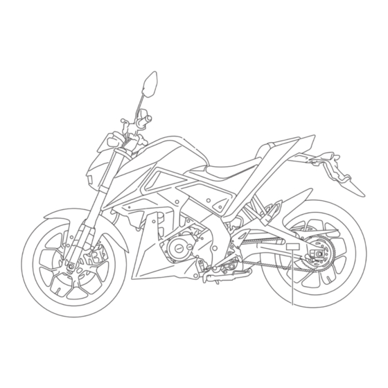
Description EAU10411 Left view 1. Headlight (page 7-31) 9. Sidestand (page 4-14) 2. Auxiliary light (page 7-31) 3. Fuel tank cap (page 4-9) 4. Air filter (page 7-15) 5. Battery (page 7-29) 6. Fuse (page 7-30) 7. Owner’s tool kit (page 7-1) 8. -
Page 18: Right View
Description EAU10421 Right view 1. Rear turn signal light (page 7-32) 2. Tail/brake light (page 7-32) 3. Front brake fluid reservoir (page 7-21) 4. Front turn signal light (page 7-32) 5. Engine oil filter element (page 7-11) 6. Dipstick (page 7-11) 7. -
Page 19: Controls And Instruments
Description EAU10431 Controls and instruments 1. Clutch lever (page 4-8) 2. Left handlebar switches (page 4-7) 3. Multi-function meter unit (page 4-4) 4. Main switch/steering lock (page 4-1) 5. Right handlebar switches (page 4-7) 6. Throttle grip (page 7-16) 7. Brake lever (page 4-9) -
Page 20: Instrument And Control Functions
Instrument and control functions EAUN0264 To lock the steering Main switch/steering lock The left headlight, meter, auxiliary and tail lighting comes on auto- matically when the key is turned to “ON”. The fuel pump can be heard when the key is turned to “ON”. -
Page 21: Keyhole Shutter
Instrument and control functions To unlock the steering EAU61101 To close the keyhole shutter Keyhole shutter Insert the key and turn it to “OFF”. Insert the keyhole shutter key into the 1. Main switch/steering lock key keyhole shutter receptacle as shown, 2. -
Page 22: Indicator Lights And Warning Lights
2. Neutral indicator light “ ” to “ON”. The warning light should 3. High beam indicator light “ ” curs, have a Yamaha dealer check the 4. Engine trouble warning light “ ” come on for a few seconds, and then self-diagnosis system. -
Page 23: Self-Diagnosis Device
“SELECT” switch. If a problem is detected in any of those circuits, the engine trouble warning light will come on or flash. If this oc- Speedometer curs, have a Yamaha dealer check the vehicle. ECA11171 NOTICE 1. Multi-function meter unit To prevent engine damage, be sure 2. - Page 24 Instrument and control functions Tachometer Odometer and tripmeters The odometer will lock at 999999 and cannot be reset. The tripmeters will reset and con- tinue counting after 9999.9 is reached. Backlight setting mode 1. Tachometer 1. Odometer/tripmeter 2. Tachometer red zone The odometer shows the total distance The tachometer allows the rider to traveled.
- Page 25 If this occurs, have 5. Push the “SELECT” switch for two and then return to current amount in or- a Yamaha dealer charge or replace the seconds to start the clock. der to test the electrical circuit.
-
Page 26: Handlebar Switches
Instrument and control functions EAU1234H EAU12361 Handlebar switches Pass switch “PASS” Press this switch to flash the headlight. Left EAU12401 Dimmer switch “ ” Set this switch to “ ” for the high beam and to “ ” for the low beam. EAU12461 Turn signal switch “... -
Page 27: Clutch Lever
Instrument and control functions EAU68270 EAU31642 EAU12872 Start/Engine stop switch “ / ” Clutch lever Shift pedal To crank the engine with the starter, set this switch to “ ”, and then slide the switch toward “ ”. See page 6-1 for starting instructions prior to starting the engine. -
Page 28: Brake Lever
Instrument and control functions EAU12892 EAU12944 EAUE1481 Brake lever Brake pedal Fuel tank cap 1. Brake lever 1. Brake pedal 1. Fuel tank cap lock cover 2. Unlock. The brake lever is located on the right The brake pedal is located on the right side of the handlebar. -
Page 29: Fuel
Instrument and control functions EAU13213 Fuel The fuel tank cap cannot be installed Make sure there is sufficient gasoline in unless the key is in the lock. In addi- the tank. tion, the key cannot be removed if the EWA10882 WARNING cap is not properly installed and locked. -
Page 30: Catalytic Converter
Instrument and control functions ately. If gasoline spills on your skin, EAU13434 ECA10702 Catalytic converter NOTICE wash with soap and water. If gaso- This model is equipped with a catalytic line spills on your clothing, change Use only unleaded gasoline. The use converter in the exhaust system. -
Page 31: Seats
Instrument and control functions EAUE2483 To install the passenger seat Seats 1. Insert the projection on the rear of the passenger seat into the seat Passenger seat holder as shown, and then push the front of the seat down to lock To remove the passenger seat it in place. -
Page 32: Helmet Holder
Instrument and control functions 2. Install the two rider seat bolts, and EAUE1311 Helmet holder then tighten the bolts to the spec- ified torque. Tightening torque: Bolt: 7 Nm (0.7 m·kgf, 5.1 ft·lbf) 3. Install the passenger seat. 1. Helmet Make sure that the seats are properly 2. -
Page 33: Sidestand
Instrument and control functions EAU37491 EAU15393 Sidestand Starting circuit cut-off system The sidestand is located on the left The starting circuit cut-off system side of the frame. Raise the sidestand (comprising the clutch switch and the or lower it with your foot while holding neutral switch) prevents starting when the vehicle upright. - Page 34 With the engine turned off: 1. Make sure that the engine stop switch is set to “ ”. If a malfunction is noted, have a Yamaha 2. Turn the key on. dealer check the system before riding. 3. Shift the transmission into the neutral position.
-
Page 35: For Your Safety - Pre-Operation Checks
• If necessary, add recommended coolant to specified level. 7-13 Coolant • Check cooling system for leakage. • Check operation. • If soft or spongy, have Yamaha dealer bleed hydraulic system. • Check brake pads for wear. Front brake • Replace if necessary. 7-20, 7-21 •... - Page 36 • Make sure that operation is smooth. • Check throttle grip free play. Throttle grip 7-16, 7-25 • If necessary, have Yamaha dealer adjust throttle grip free play and lubricate ca- ble end and grip housing. • Make sure that operation is smooth. Control cables 7-25 •...
- Page 37 For your safety – pre-operation checks ITEM CHECKS PAGE • Make sure that all nuts, bolts and screws are properly tightened. Chassis fasteners — • Tighten if necessary. Instruments, lights, signals • Check operation. — and switches • Correct if necessary.
-
Page 38: Operation And Important Riding Points
Yamaha dealer check its electrical circuit. [ECAT1121] 2. Shift the transmission into the neutral position. The neutral indi- cator light should come on. If not, ask a Yamaha dealer to check the electrical circuit. 3. Start the engine by pushing the start switch. -
Page 39: Shifting
Operation and important riding points If the engine fails to start, release EAU16673 ECA10261 Shifting NOTICE the start switch, wait a few sec- Even with the transmission in onds, and then try again. Each starting attempt should be as the neutral position, do not short as possible to preserve the coast for long periods of time... -
Page 40: Tips For Reducing Fuel Consumption
Yamaha dealer check the vehi- to the correct operating clearances. gine. cle. Turn the engine off instead of let-... -
Page 41: Parking
Operation and important riding points EAU17214 Parking When parking, stop the engine, and then remove the key from the main switch. EWA10312 WARNING Since the engine and exhaust system can become very hot, park in a place where pedestri- ans or children are not likely to touch them and be burned. -
Page 42: Periodic Maintenance And Adjustment
If If you do not have the tools or experi- you are not familiar with vehicle ser- ence required for a particular job, have vice, have a Yamaha dealer perform a Yamaha dealer perform it for you. service. -
Page 43: Periodic Maintenance Chart For The Emission Control System
The annual checks must be performed every year, except if a kilometer-based maintenance is performed in- stead. From 20000 km, repeat the maintenance intervals starting from 4000 km. Items marked with an asterisk should be performed by a Yamaha dealer as they require special tools, data and tech- nical skills. EAUU1293... -
Page 44: General Maintenance And Lubrication Chart
Periodic maintenance and adjustment EAUU1286 General maintenance and lubrication chart ODOMETER READING (whichever comes first) ANNUAL 1000 km 4000 km 8000 km 12000 km 16000 km ITEM CHECK OR MAINTENANCE JOB CHECK 2 months 6 months 10 months 14 months 18 months √... - Page 45 Periodic maintenance and adjustment ODOMETER READING (whichever comes first) ANNUAL 1000 km 4000 km 8000 km 12000 km 16000 km ITEM CHECK OR MAINTENANCE JOB CHECK 2 months 6 months 10 months 14 months 18 months • Check bearings for looseness or √...
- Page 46 Periodic maintenance and adjustment ODOMETER READING (whichever comes first) ANNUAL 1000 km 4000 km 8000 km 12000 km 16000 km ITEM CHECK OR MAINTENANCE JOB CHECK 2 months 6 months 10 months 14 months 18 months • Check operation. √ √...
- Page 47 Periodic maintenance and adjustment EAU18662 The air filter needs more frequent service if you are riding in unusually wet or dusty areas. Hydraulic brake service • Regularly check and, if necessary, correct the brake fluid level. • Every two years replace the internal components of the brake master cylinder and caliper, and change the brake fluid.
-
Page 48: Removing And Installing Panels
Periodic maintenance and adjustment EAU18773 Removing and installing pan- The panels shown need to be removed to perform some of the maintenance jobs described in this chapter. Refer to this section each time a panel needs to be removed and installed. 1. - Page 49 Periodic maintenance and adjustment Panel B To remove a panel 1. Remove panel A. (See page 7-7.) 2. Remove the bolts, and then take the panel off. 1. Panel C 2. Install panel A. 2. Screw Panel C To install the panel 1.
-
Page 50: Checking The Spark Plug
Periodic maintenance and adjustment Panel D EAUU1970 Checking the spark plug The spark plug is an important engine To remove a panel component, which is easy to check. 1. Remove panel C. (See page 7-7.) Since heat and deposits will cause any 2. -
Page 51: To Check/Install Spark Plug
1. Spark plug gap 4. Install the panel. ating improperly. Do not attempt to Spark plug gap: diagnose such problems yourself. In- 0.7–0.8 mm (0.031–0.031 in) stead, have a Yamaha dealer check the vehicle. 7-10... -
Page 52: Engine Oil And Oil Filter Element
Periodic maintenance and adjustment EAUE0453 4. If the engine oil is below the mini- Engine oil and oil filter ele- mum level mark, add sufficient oil ment of the recommended type to raise The engine oil level should be checked it to the correct level. - Page 53 Periodic maintenance and adjustment 7. Install the oil filter element cover by installing the bolts, then tight- ening them to the specified torque. Tightening torques: Oil filter element cover bolt: 10 Nm (1.0 m·kgf, 7.2 ft·lbf) ZAUE0672 ZAUE1217 1. Engine oil drain bolt 1.
-
Page 54: Coolant
Periodic maintenance and adjustment 9. Refill with the specified amount of 10. Start the engine, and then let it idle EAU20071 Coolant the recommended engine oil, and for several minutes while checking The coolant level should be checked then install and tighten the oil filler it for oil leakage. - Page 55 Have a be protected against frost and Yamaha dealer change the coolant. corrosion. If water has been WARNING! Never attempt to remove added to the coolant, have a...
-
Page 56: Cleaning The Air Filter Element
Periodic maintenance and adjustment EAUE0482 5. Lightly tap the air filter element to Cleaning the air filter element remove the most of the dust and If dust or water collects in the air filter The air filter element should be cleaned dirt, and then blow the remaining check hose, remove the clamp, and at the intervals specified in the periodic... -
Page 57: Adjusting The Engine Idling Speed
If the specified idling speed cannot be follows at the intervals specified in the obtained as described above, have a periodic maintenance and lubrication Yamaha dealer make the adjustment. chart. The engine should be warm before making this adjustment. Check the engine idling speed and, if necessary, adjust it to specification by turning the idle adjusting screw. -
Page 58: Valve Clearance
Therefore, it must be adjusted by a Yamaha dealer is essential to maintain the tires in good at the intervals specified in the periodic condition at all times and replace them maintenance and lubrication chart. - Page 59 EWA10512 has a nail or glass fragments in it, or if characteristics. WARNING the sidewall is cracked, have a Yamaha Never overload your vehicle. Opera- dealer replace the tire immediately. Tire information tion of an overloaded vehicle could...
-
Page 60: Cast Wheels
If any damage is found, have could lead to an accident. a Yamaha dealer replace the After extensive tests, only the tires list- wheel. Do not attempt even the ed below have been approved for this smallest repair to the wheel. -
Page 61: Checking The Front And Rear Brake Pads
Periodic maintenance and adjustment 3. To increase the clutch lever free 6. To increase the clutch lever free EAU22393 Checking the front and rear play, turn the clutch lever free play play, turn the clutch lever free play brake pads adjusting bolt in direction (a). -
Page 62: Checking The Brake Fluid Level
EAU22582 Rear brake Checking the brake fluid level peared, have a Yamaha dealer replace Before riding, check that the brake fluid the brake pads as a set. is above the minimum level mark. Check the brake fluid level with the top... -
Page 63: Changing The Brake Fluid
EAUM1362 Changing the brake fluid id; otherwise, the rubber seals Yamaha dealer check the cause before Have a Yamaha dealer change the may deteriorate, causing leak- further riding. brake fluid at the intervals specified in age. -
Page 64: Drive Chain Slack
2. Shift the transmission into the To adjust the drive chain slack chain, turn the adjusting bolt on neutral position. Consult a Yamaha dealer before ad- each side of the swingarm in di- 3. Measure the drive chain slack as justing the drive chain slack. -
Page 65: Cleaning And Lubricating The Drive Chain
Periodic maintenance and adjustment 4. Make sure that the drive chain EAUE0141 Cleaning and lubricating the pullers are in the same position, Using the alignment marks on each drive chain the drive chain slack is correct, side of the swingarm, make sure that The drive chain must be cleaned and drive chain... -
Page 66: Checking And Lubricating The Cables
Yamaha dealer at the inter- sary. If a cable is damaged or does not vals specified... -
Page 67: Checking And Lubricating The Brake And Shift Pedals
Periodic maintenance and adjustment EAU44276 EAU23144 Recommended lubricant: Checking and lubricating the Checking and lubricating the Lithium-soap-based grease brake and shift pedals brake and clutch levers The operation of the brake and shift The operation of the brake and clutch pedals should be checked before each levers should be checked before each ride, and the pedal pivots should be lu-... -
Page 68: Checking And Lubricating The Sidestand
EWA10732 WARNING If the sidestand does not move up and down smoothly, have a Yamaha dealer check or repair it. Otherwise, the sidestand could contact the ground and distract the operator, re- sulting in a possible loss of control. -
Page 69: Checking The Front Fork
[EWA10752] tion. WARNING! To avoid injury, 2. Hold the lower ends of the front have a Yamaha dealer check or re- fork legs and try to move them for- securely support the vehicle so pair it. -
Page 70: Checking The Wheel Bearings
To charge the battery working near batteries. In case Have a Yamaha dealer charge the bat- of contact, administer the fol- lowing FIRST AID. tery as soon as possible if it seems to have discharged. -
Page 71: Replacing The Fuse
Periodic maintenance and adjustment ECA16522 4. After installation, make sure that EAUE1423 Replacing the fuse NOTICE the battery leads are properly con- The fuse box is located under the rider nected to the battery terminals. To charge a VRLA (Valve Regulated seat. -
Page 72: Headlight
4. Turn the key to “ON” and turn on If a headlight does not come on, have If an auxiliary light does not come on, the electrical circuits to check if a Yamaha dealer check its electrical have a Yamaha dealer check it. the devices operate. circuit. -
Page 73: Tail/Brake Light
If the tail/brake light does not come on, when removing the front and rear by removing the screw. have a Yamaha dealer check it. wheel or performing other mainte- nance requiring the motorcycle to stand upright. Check that the motorcy- cle is in a stable and level position be- fore starting any maintenance. -
Page 74: Front Wheel
Periodic maintenance and adjustment a jack either under each side of the EAU24361 3. Remove the brake hose holder by Front wheel frame in front of the rear wheel or under removing the bolt. each side of the swingarm. 4. Remove the brake caliper by re- EAUN0582 moving the bolts. -
Page 75: Rear Wheel
Periodic maintenance and adjustment To install the front wheel EAU25081 3. Remove the drive chain case by Rear wheel 1. Lift the wheel up between the fork removing the bolts along with the legs. collar. EAUN0590 2. Insert the wheel axle and install the wheel axle nut. - Page 76 Periodic maintenance and adjustment 5. Lift the rear wheel off the ground To install the rear wheel according to the procedure on 1. Install the wheel and the brake cal- If the drive chain is difficult to re- page 7-32. iper bracket by inserting the wheel move, remove the wheel axle first, 6.
-
Page 77: Troubleshooting
Tightening torques: self. However, should your motorcycle Axle nut: 90 Nm (9.0 m·kgf, 65 ft·lbf) require any repair, take it to a Yamaha Locknut: dealer, whose skilled technicians have 16 Nm (1.6 m·kgf, 12 ft·lbf) the necessary tools, experience, and know-how to service the motorcycle properly. -
Page 78: Troubleshooting Charts
Remove the spark plug and check the electrodes. The engine does not start. Have a Yamaha dealer check the vehicle. Check the compression. 4. Compression The engine does not start. There is compression. - Page 79 Start the engine. If the engine overheats again, have a The coolant level Yamaha dealer check and repair the cooling system. is OK. If coolant is not available, tap water can be temporarily used instead, provided that it is changed to the recommended cool- ant as soon as possible.
-
Page 80: Motorcycle Care And Storage
Rust and corrosion can develop matte colored finished parts. Be Cleaning even if high-quality components are sure to consult a Yamaha dealer for ECA10773 NOTICE used. A rusty exhaust pipe may go un- advice on what products to use be- noticed on a car, however, it detracts fore cleaning the vehicle. - Page 81 Motorcycle care and storage off any detergent residue using shield. Test the product on a plenty of water, as it is harmful small hidden part of the wind- Salt sprayed on roads in the winter to plastic parts. shield to make sure that it does may remain well into spring.
-
Page 82: Storage
EWA11132 poorly ventilated room or cover- WARNING ing it with a tarp, while it is still Consult a Yamaha dealer for ad- Contaminants on the brakes or tires wet, will allow water and humid- can cause loss of control. - Page 83 Motorcycle care and storage 2. Fill up the fuel tank and add fuel e. Remove the spark plug cap stabilizer (if available) to prevent from the spark plug, and then Make any necessary repairs before the fuel tank from rusting and the install the spark plug and the storing the motorcycle.
-
Page 84: Specifications
Specifications Dimensions: Engine oil: Transmission: Overall length: Recommended brand: Primary reduction ratio: 1955 mm (77.0 in) YAMALUBE 3.042 (73/24) Overall width: Type: Final drive: 795 mm (31.3 in) SAE 10W-40 Chain Overall height: Engine oil quantity: Secondary reduction ratio: 1065 mm (41.9 in) Without oil filter element replacement: 3.133 (47/15) Seat height:... - Page 85 Specifications Size: Rim size: Charging system: 110/70-17M/C 54S 17M/C x MT3.50 AC magneto Manufacturer/model: Front brake: Battery: IRC/NR88 Type: Model: Rear tire: Single disc brake GTZ4V Type: Operation: Voltage, capacity: Tubeless Right hand operation 12 V, 3.0 Ah Bulb voltage, wattage × quantity: Size: Specified brake fluid: 130/70-17M/C 62S...
-
Page 86: Consumer Information
Record the vehicle identification num- ber and the engine serial number in the spaces provided below for assistance when ordering spare parts from a Yamaha dealer or for reference in case the vehicle is stolen. VEHICLE IDENTIFICATION NUMBER: ZAUE0617 1. Vehicle identification number 1. -
Page 87: Index
Index Fuel ............4-10 Fuel consumption, tips for reducing ..6-3 Air filter element, cleaning ....7-15 Safe-riding points ........2-5 Fuel tank cap.......... 4-9 Auxiliary lights........7-31 Safety information........2-1 Fuse, replacing........7-30 Seats............. 4-12 Self-diagnosis device ......4-4 Battery .......... - Page 88 Index Wheel bearings, checking.....7-29 Wheel (front)..........7-33 Wheel (rear)...........7-34 Wheels ..........7-19 11-2...
- Page 90 PRINTED IN THAILAND 2017.07 (E)
Need help?
Do you have a question about the M-Slaz TFX150 and is the answer not in the manual?
Questions and answers
Color code of TFX 150 ECU
@Lhander simsim