Advertisement
*23697279*
23697279
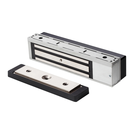
Electromagnetic Locks
Cover Screws (4)
Cover
Magnet Screws (2)
* Two armature bolts may be included in the package, but only one is used. There may be one left over after proper installation.
** Screws for both reinforced metal and sheet metal are included. Some screws will be left over after proper installation. See individual steps for screw identification.
M490DE
Armature Bolt*
Conical Washer
Star Locking Washer
Installation Instructions
Flat Washer
Mounting Bracket
Outside Mounting
Bracket Screws** (4)
Inside Mounting
Bracket Screws** (2)
Magnet Assembly
Armature Plate
Armature Holder
Screws (2)
Armature Holder
Sex Nut
Advertisement
Table of Contents

Related Manuals for Schlage M490DE


Summary of Contents for Schlage M490DE
- Page 1 *23697279* M490DE 23697279 Electromagnetic Locks Installation Instructions Mounting Bracket Cover Screws (4) Outside Mounting Bracket Screws** (4) Inside Mounting Bracket Screws** (2) Cover Magnet Assembly Armature Plate Armature Holder Screws (2) Magnet Screws (2) Armature Holder Armature Bolt* Sex Nut...
-
Page 2: Pre-Installation Considerations
Cautions may also warn against unsafe practices. LED Status and Audible Alarm Models Pre-Installation Considerations M490DE (Single Lock Basic) M490DE-2 (Double Lock Basic) • Use ONLY the hardware provided for mounting this product Delayed Egress, Automatic Double lock with same features... -
Page 3: Lock Installation
Lock Installation Prepare for installation. 1a Determine proper magnet orientation. Single Door Magnet should be placed opposite of door hinges. Wiring Cover Wiring Cover Magnet Magnet LHR Door - Shown from Exterior RHR Door - Shown from Exterior Double Door Locks should be installed with wiring covers in the middle, so the magnet in one of the locks must be reoriented. - Page 4 1b Reorient magnet and board (if necessary). End Block (with screw holes) Board Spacer a. Remove screws, wiring cover and end blocks. Wiring Cover Front Side of Lock Magnet b. Remove board. End Block c. Rotate magnet, end End Block blocks and wiring cover as shown, then reassemble.
- Page 5 Attach armature to door. 2a Install armature holder. CAUTION Armature holder screws must be flush to inside of armature holder. OUTSIDE 2b Install armature plate as shown for door type (M420/M450 shown). WARNING Correct Incorrect Armature bolt must be tightened to at least 120 in.-lbs. for all doors except composite wood doors. For composite wood doors, tighten only to tight and flush.
- Page 6 Install mounting bracket into frame. 3a Attach mounting bracket temporarily. 3d Verify that DE plunger aligns with screw head on armature. Install two middle screws into slots and partially tighten. Verify DE plunger switch is activated when door is closed. Re-adjust position Oustide of mounting bracket to achieve proper switch activation if necessary.
-
Page 7: Install Lock
Install lock 4a Install magnet and secure with screws. Actual Size Connect wiring to board (basic model). 5a Connect plug and wires to board. Power Input Fire Alarm Input Reset Input Release Input Auxiliary Input Alarm Output (Optional) 12/24V DC Apply a Dry contact Dry contact... - Page 8 5c Install cover using spanner wrench and security screws. Spanner Wrench Actual Size Connect wiring to board (plus model). 6a Connect plugs to board. DPS2 DPS1 COILS MBS2 MBS1 6b Connect wires to board. Power Input Fire Alarm Input Reset Input Release Input Auxiliary Input DPS Output...
- Page 9 6d Set SW2 dip switches. NOTE: Dip switch panel may be upside-down, depending on installation. Look for the “OFF” label and compare to the images below for correct dip switch positions. Feature Switch Setting Description Nuisance Delay 0 seconds 1 second 2 seconds 3 seconds Nuisance delay is the amount of time the door must be pushed or...
- Page 10 6g Install cover. Spanner Wrench Actual Size If double door, install second lock (M490DE-2 or M490DEP-2). 7a Install second lock. 7b Install communication cable. a. Reorient as needed as shown in step 1b. a. Route cable (supplied) through frame. b. Install lock as shown in steps 2-4.
- Page 11 7c Connect wiring to second lock. *DPS2 *DPS1 COILS *MBS2 *MBS1 *DPS Wiring in Parallel DPS Output (Plus Models Only) 12V@200mA Second 24V@100mA auxiliary input resistive Both doors closed. (NO) If either or both doors (NC) open, contacts will change Master Lock (Basic or Plus) 7d Install covers.
-
Page 12: Troubleshooting
Indicator Table Condition LED Indicator Audible Alarm Relay State Standard Features Lock Secure Open Authorized Release Input Steady Green Open During Nuisance Delay Steady Red Off (Default) Open Set by SW2-3 During Fire Alarm Steady Green Closed During Delayed Egress Flashing Red Beeping Closed...
Need help?
Do you have a question about the M490DE and is the answer not in the manual?
Questions and answers