Advertisement
Quick Links
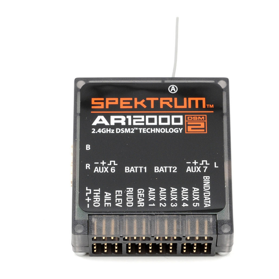
AR12000 User Guide
Battery Requirements
Using One Battery
The AR12000 full range 12-channel receiver features DSM2
™
technology and is compatible with all
The AR12000 allows the option of using one or two battery packs. When using one battery, simply
Spektrum
™
and JR
®
aircraft radios that support DSM2 technology including Spektrum DX7, Spektrum
plug the battery into either one of the two battery connectors (BATT 1 or BATT2). When using dual
DX6i, Spektrum DX5e, Spektrum Module Systems, JR12X, JRX9303.
batteries, it's recommended that both batteries be of the same capacity, voltage and ideally of the
Note: The AR12000 receiver is not compatible with the Spektrum DX6 parkflyer transmitter.
same age/previous profile. When using two batteries the total available capacity equals the sum
total of both batteries (e.g. BATT1- 2000mAh + BATT2- 2000mAh= a total capacity of 4000mAh).
Features:
Battery Capacity
• 12-Channel Full Range Receiver with Dual Battery Ports
• Patented MultiLink
™
receiver technology with up to four receivers
It's important to select a battery(s) that has more than adequate capacity to provide the necessary
• Includes one internal and three remote receivers
flight time. Our staff has been recording in-flight data to determine typical current consumption
• Two type of failsafe SmartSafe
™
and Preset Failsafe
of aircraft in flight. Following are two graphs that illustrate the in-flight current draw of the radio
system.
• QuickConnect
™
with Brownout Detection
• Flight Log Compatible (optional)
Note: Current draws may vary depending on your servos, installation, and flying style.
Applications
The following setup is shown as a worst case scenario indicative of some aerobatic pilots' setups. It
Full Range Up to 12-channel aircraft including:
is not recommended to use this setup without proper voltage regulation for your servos.
Giant-scale aircraft
Airplane - 40% YAK
Jets
Scale aircraft
Large scale helicopters
Giant-scale racing airplanes
Aircraft with multiple functions
Specifications:
Type: DSM2 Full Range Receiver
Channels: 12
Modulation: DSM2
Dimension (WxLxH): 46.5 x 52 x 15.3mm
Weight: 40 g
Input Voltage Range: 4.8–10V
Resolution: 2048
0
Items Included:
• Receiver main unit - SPMAR12000
• Three remote receivers - SPM9545
Servos - 9-JR8711's 1-8317 (throttle)
• One 24" remote receiver extension - SPM9013
• One 12" remote receiver extension - SPM9012
Batteries - Two 4000mAh 2-cell 7.4-volt LiPo's
Regulator - none
• One 9" remote receiver extension - SPM9011
• User Guide
Note: JR8711's and 8317's are rated at a maximum of 6-volt 5-cell use. Using higher voltages will
• Male/Female bind plug - SPM6803
void the warranty.
Optional Items
Engine - DA150
• Flight Log data recorder - SPM9540
Weight - 40 lb
Flight envelope - Aggressive 3D
• Replacement remote receiver - SPM9545
• 6" Remote receiver extension - SPM9010
Average current - 2.62 amps
Peak current - 17.8 amps
• 9" Remote receiver extension - SPM9011
• 12" Remote receiver extension - SPM9012
Milliamps used per 10 minute flight - 435mAh
• 24" Remote receiver extension - SPM9013
In the example above, the average current was 2.62 amps, which calculates to 435mAh per 10
• 36" Remote receiver extension - SPM9014
minutes (typical flight length). It's recommended that only 60% of the available capacity be used to
• 6" Quick Disconnect Remote receiver extension - SPMAJST3
ensure plenty of reserve battery capacity. In this example, using two 4000mAh batteries (8000mAh
• 12" Quick Disconnect Remote receiver extension - SPMAJST6
total capacity) x 60%= 4800mAh (available usable capacity) divided by the capacity used per 10
minute flight, 435mAh would allow up to 11 flights of 10 minutes each.
Airplane - 33% Sukhoi
0
50
100
150
Servos - 7-JR8611's 1-8317 (throttle)
Batteries - 1- 4000mAh 2-cell 7.4-volt LiPo's
File: JasonNoll.FDR Session:All Sessions
Regulator - 6 volts
18
Engine - DA100
17
16
Weight - 26 lb
15
Flight envelope - Moderate 3D
14
13
Average current - .82 amps
12
Peak current - 6.92 amps
11
10
Milliamps used per 10 minute flight - 137mAh
9
8
Recommended Guidelines for Battery Capacity
7
6
40-45% Aerobatic aircraft w/ 9–12 high current servos: 4000-8000mAh
5
4
33-35% Aerobatic aircraft w/ 7–10 high current servos: 3000-6000mAh
3
2
25% Quarter Scale Aerobatic aircraft w/ 5–7 high current servos: 2000-4000mAh
1
Jets - BVM Super BANDIT, F86, Euro Sport, etc.: 3000-6000mAh
0
50
100
150
200
250
300
350
400
450
Giant-Scale Jets - BVM Ultra Bandit: 4000-8000mAh
Seconds
PackAmps_A: Min 0.00 Max 17.80 Avg 2.62
Scale aircraft: The variety of scale aircraft and the accessories they use vary tremendously
making it difficult to give capacity recommendations for these types of aircraft. Using the above
aerobatic guidelines relative to the size and number of servos used will provide a conservative
capacity for your scale aircraft. As always, check battery charge condition before each flight.
IMPORTANT: DO not use a 4-cell 4.8-volt battery to power the receiver.
Four-cell 4.8-volt batteries do not provide enough voltage head room (additional margin needed)
necessary to power the system when heavily loaded. Under load, the system voltage can drop below
the voltage system's minimum operating voltage threshold (3.5 volts) and cause loss of control.
The AR12000 is capable of handling voltages from 6.0 to 10.0 volts. The voltage limitations are
generally the servos. Most servos are compatible with 5-cell 6-volt packs, however, and 5-cell
6-volt NiMH packs have become the standard for many giant-scale applications.
Be aware that NiMH batteries have tendencies to false peak when being fast charged. Be especially
careful and sure when using NiMH batteries that they are fully charged and have not false peaked.
Many pilots are using 2-cell LiPo batteries to power their aircraft. LiPo's offer greater capacity for
their size and weight, plus it is easier to manage the charging.
Receiver
The AR12000 incorporates one internal receiver, and requires at least two external receivers (three
are included) offering the security of multi-path RF redundancy. One internal receiver is located on
the main PC board, while two external receivers must be attached to the main board with exten-
sions. Additionally a fourth receiver is included and can be added offering the ultimate in RF link
security and redundancy. By locating each receiver in slightly different locations in the aircraft, each
receiver is exposed to its own RF environment, greatly improving path diversity (the ability for the
receiver to see the signal in all conditions).
Antenna Polarization
For optimum RF link performance it's important that the antennas be mounted in an orientation that
File: sukhio Session:All Sessions
allows for the best possible signal reception when the aircraft is in all possible attitudes and posi-
7
tions. This is known as antenna polarization. The antennas should be oriented perpendicular to each
6.5
other; typically vertical and horizontal and at different angles (see Receiver Installation below). The
6
5.5
remote receiver antenna should be mounted in a position perpendicular at least 2 inches away from
5
the main receiver's antenna using double-sided foam tape.
4.5
4
Receiver Installation in Aircraft
3.5
3
In gas, turbine and glow aircraft install the main receiver using the same method you would use to
2.5
install a conventional receiver in your aircraft. Typically, wrap the main receiver in protective foam
2
1.5
and fasten it in place using rubber bands or hook and loop straps. Alternately, in electric airplanes
1
or helicopters, it's acceptable to use thick double-sided foam tape to fasten the main receiver in
0.5
place. The AR12000 requires at least two remote receivers to operate. Mounting these remote receiv-
0
200
250
300
350
400
450
ers in different locations, even just inches away from the primary receiver, gives tremendous improve-
Seconds
PackAmps_A: Min 0.00 Max 6.92 Avg 0.82
ments in path diversity. Essentially, each receiver sees a different RF environment and this is key to
maintaining a solid RF link, even in aircraft that have substantial conductive materials (e.g. larger gas
engines, carbon fiber, pipes, etc.), which can weaken the signal. Using servo tape, mount the remote
receivers keeping the remote antennas at least 2 inches away from the primary antennas. Ideally, the
antennas will be oriented perpendicularly to each other. In airplanes, we've found it best to mount the
primary receiver in the center of the fuselage on the servo tray and to mount the remote receivers to the
side of the fuselage or in the turtle deck. A fourth antenna can be added for additional RF link security.
Important: Y-Harnesses and Servo Extensions
When using a Y-harness or servo extensions in your installation, it' s important to use standard non-
amplified Y-harnesses and servo extensions as this can/will cause the servos to operate erratically
or not function at all. Amplified Y-harnesses were developed several years ago to boost the signal
for some older PCM systems and should not be used with Spektrum equipment. Note that when
converting an existing model to Spektrum be certain that all amplfied Y-harnesses and/or servo
extensions are replaced with conventional non-amplified versions.
Binding
Failsafe functions
The AR12000 receiver must be bound to the transmitter before it will operate. Binding is the process
The AR12000 features two types of failsafe: SmartSafe and Preset Failsafe.
of teaching the receiver the specific code of the transmitter so it will only connect to that specific
SmartSafe
transmitter.
This type of failsafe is recommended for most types of aircraft. Here' s how SmartSafe works.
1. To bind an AR12000 to a DSM2 transmitter, insert the bind plug in the BATT/BIND port on the receiver.
When the transmitter and receiver are turned on the receiver connects to the transmitter and normal
control of all channels occurs. If loss of signal occurs, SmartSafe drives the throttle servo only to its
preset failsafe position (low throttle) that was set during binding. All other channels hold their last
position. When the signal is regained, the system immediately regains control.
Preset Failsafe
Preset failsafe is ideal for sailplanes and is preferred by some modelers for their glow- and gas-
powered aircraft.
When the transmitter and receiver are turned on and the receiver connects to the transmitter normal
control of all channels occurs. If loss of signal occurs Preset failsafe drives all servos to their preset
failsafe positions. For sailplanes it' s recommended that the spoilers/flaps deploy to de-thermalize the
aircraft, preventing a flyaway. Some powered modelers prefer to use this failsafe system to program a
slight turn and low throttle to prevent their aircraft from flying away. When the signal is regained, the
2. Power the receiver. Note that the LED on all receivers should be flashing, indicating that the receiver
system immediately regains control.
is in bind mode and ready to be bound to the transmitter.
Programming SmartSafe
During the binding process the bind plug is left in throughout the process and is removed only after
the receiver connects to the transmitter. After the connection is made, confirmed by operating the
servos, the bind plug can be removed. The receiver is now programmed for SmartSafe.
Programming Preset Failsafe
During the binding process the bind plug is inserted in the bind port, then the receiver is powered
up. The LEDs in each receiver should blink, indicating that the receiver is in bind mode. Now before
binding the receiver to the transmitter and with the receiver in bind mode, remove the bind plug. The
LEDs will still be blinking. With the control sticks and switches in the desired failsafe positions, bind
the transmitter to the receiver. Follow the procedures of your specific transmitter to enter Bind Mode.
Shown using a separate receiver pack.
(Battery can be plugged into either BATT port.)
The system should connect in less than 15 seconds. The receiver is now programmed for preset
failsafe.
3. Move the sticks and switches on the transmitter to the desired failsafe positions (low throttle and
Note: Failsafe positions are stored via the stick and switch positions on the transmitter during binding.
neutral control positions).
Receiver Power Only
• With SmartSafe or Preset Failsafe, when the receiver only is turned on (no transmitter signal is
present), the throttle channel has no output, to avoid operating or arming the electronic speed control.
• All other channels are driven to their preset failsafe positions set during binding.
Note: Some analog servos may coast slightly even though no signal is present. This is normal.
Plugging in the Leads
Plug the servo leads into the appropriate servo ports in the receiver noting the polarity of the
servo connector.
Range Testing
Before each flying session and especially with a new model, it is important to perform a range check.
All Spektrum aircraft transmitters incorporate a range testing system which, when activated, reduces
the output power, allowing a range check.
4. Follow the procedures of your specific transmitter to enter Bind Mode, the system will connect
within a few seconds. Once connected, the LED on the receiver will go solid indicating the system
is connected.
5. Remove the bind plug from the BATT/BIND port on the receiver before you power off the transmitter
and store it in a convenient place.
6. After you've set up your model, it' s important to rebind the system so the true low throttle and
neutral control surface positions are set.
IMPORTANT: Remove the bind plug to prevent the system from entering bind mode the next time the
power is turned on.
1. With the model restrained on the ground, stand 30 paces (approx. 90 feet/28 meters) away from
the model.
30 paces (90 feet/28 meters)
Press and hold the bind button
Advertisement

Subscribe to Our Youtube Channel
Related Manuals for Spectrum AR12000


Summary of Contents for Spectrum AR12000
- Page 1 1. To bind an AR12000 to a DSM2 transmitter, insert the bind plug in the BATT/BIND port on the receiver. When the transmitter and receiver are turned on the receiver connects to the transmitter and normal remote receiver antenna should be mounted in a position perpendicular at least 2 inches away from Note: The AR12000 receiver is not compatible with the Spektrum DX6 parkflyer transmitter.
- Page 2 By submitting the item for repair you are agreeing to payment of the repair without notification. Repair No. HH2008123101 1. Plug a Flight Log (SPM9540) into the data port in the AR12000 and turn on the system (Tx and Rx). PURCHASER. This warranty covers only those Products purchased from an authorized Horizon dealer.
Need help?
Do you have a question about the AR12000 and is the answer not in the manual?
Questions and answers