Advertisement
Quick Links
AR6110/6110e User Guide
The AR6110/AR6110e features DSM2
™
technology and is compatible with all Spektrum
™
and JR
®
aircraft transmitters that support DSM2 technology, like the DX7, DX6i, DX5e, 12X, X9303 and
Module Systems.
Note: The AR6110/AR6110e receivers are not compatible with the DX6 park flyer radio system.
Features
• 6-Channel Park flyer receiver
• QuickConnect
™
with Brownout Detection
• Available with Vertical or End-Pin configuration for specific installations
• Red LED indicates number of holds
Applications
Parkflyer Aircraft Only
Including: Small electric and non-powered airplanes. Mini and micro electric helicopters
up to 450 size.
Note: Not for use in airplanes that have significant carbon or conductive structures.
Specifications:
Type: Parkflyer
Channels: 6
Modulation: DSM
Dimension (WxLxH): AR6110 - 18.85 x 25 x 11.6mm
AR6110e - 21 x 28.7 x 10mm
Weight: AR6110 - 3.5 g
AR6110e - 4.0 g
Input Voltage Range: 3.5–9.6V
Resolution: 1024
Compatibility: All DSM2 Aircraft Transmitters and Module Systems
Receiver Installation
AR6110e installed in airplane
In electric airplanes, it is recommended that double-sided foam tape be used to secure the
AR6110/AR6110e in a position recommended by the aircraft manufacturer.
AR6110 installed in Heli
In electric helicopters, it is recommended that double-sided foam tape be used to secure
the AR6110/AR6110e in a position that locates the receiver away from the motor and ESC
where possible.
Important: Y-Harnesses and Servo Extensions
When using a Y-harness or servo extensions in your installation, it' s important to use standard non-
amplified Y-harnesses and servo extensions as this can/will cause the servos to operate erratically
or not function at all. Amplified Y-harnesses were developed several years ago to boost the signal
for some older PCM systems and should not be used with Spektrum equipment. Note that when
converting an existing model to Spektrum be certain that all amplified Y-harnesses and/or servo
extensions are replaced with conventional non-amplified versions.
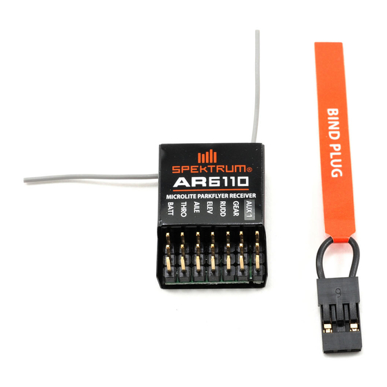
Binding
The AR6110/AR6110e receiver must be bound to the transmitter before it will operate. Binding is
the process of teaching the receiver the specific code of the transmitter so it will only connect to that
specific transmitter.
1. To bind an AR6110/AR6110e to a DSM2 transmitter, insert the bind plug in the BATT/BIND port on
the receiver.
Note: To bind an aircraft with an electronic speed controller that powers the receiver through the
throttle channel (ESC/BEC), insert the bind plug into the BATT/BIND port in the receiver and the
throttle lead into the throttle (THRO) port. Proceed to Step #2.
2. Power the receiver. Note that the LED on the receiver should be flashing, indicating that the receiver
is in bind mode and ready to be bound to the transmitter.
3. Move the sticks and switches on the transmitter to the desired failsafe positions (low throttle and
neutral control positions).
4. Follow the procedures of your specific transmitter to enter Bind Mode, the system will connect
within a few seconds. Once connected, the LED on the receiver will go solid indicating the system
is connected.
5. Remove the bind plug from the BATT/BIND port on the receiver before you power off the transmitter
and store it in a convenient place.
6. After you've set up your model, it' s important to rebind the system so the true low throttle and
neutral control surface positions are set.
IMPORTANT: Remove the bind plug to prevent the system from entering bind mode the next time the
power is turned on.
AR6110/AR6110e Failsafe
•Preventsunintentionalelectricmotorresponseonstart-up.
•Establisheslow-throttlefailsafeiftheRFsignalislost.
• The AR6110(e) removes servo output pulses to all channels except the throttle channel during failsafe.
• T heAR6110(e) throttle failsafe position is stored via the throttle stick position on the transmitter
during binding.
HOW AR6110/AR6110e FAILSAFE WORKS
Receiver Power Only
• I nelectricaircraft,whenthereceiveronlyisturnedon(notransmittersignalispresent),thethrottle
channel has no output, to avoid operating or arming the electronic speed control.
• I nglow-poweredmodels,thethrottleservoreceivesnoinputsoitremainsinitscurrentposition.
Note: Some analog servos may coast slightly even though no signal is present. This is normal.
After Connection
• W henthetransmitteristurnedon,andafterthereceiverconnectstothetransmitter,normalcontrol
of all channels occurs.
• A fterthesystemmakesaconnection,iflossofsignaloccurs,theAR6110(e) Failsafe drives the
throttle servo only to its preset failsafe position (low throttle) that was set during binding.
•Allotherchannelsreceivenooutputpulses/commands,andarenotactiveduringfailsafe.
Plugging in the Leads
Plug the servo leads into the appropriate servo ports in the receiver noting the polarity of the
servo connector.
Red LED Hold Indicator
The AR6110/AR6110e features a red LED that indicates the number of holds that have occurred since
the receiver was last powered on. The LED will flash the number of holds then pause (e.g., flash,
flash, flash, pause, flash, flash, flash, pause indicates three holds occurred since the receiver was last
turned on). Note that holds are reset to zero when the receiver is turned off. During the first flights of a
new airplane, it' s recommended to check the red LED hold indicator. If it' s flashing, it's important to
optimize the installation (move or reposition antennas) until no hold occurs. On later flights, the LED
Hold Indicator can be used to confirm RF link performance.
Range Testing
Before each flying session and especially with a new model, it is important to perform a range check.
All Spektrum aircraft transmitters incorporate a range testing system which, when activated, reduces
the output power, allowing a range check.
30 paces (90 feet/28 meters)
Pull and hold the Trainer Switch
1. With the model restrained on the ground, stand 30 paces (approx. 90 feet/28 meters) away from the
model.
2. Face the model with the transmitter in your normal flying position and place your transmitter into
range check mode.
3. You should have total control of the model with the button depressed at 30 paces (90 feet/28 meters).
4. If control issues exist, call the Spektrum Service Center in the U.S. at 1-877-504-0233 for further
assistance. In the United Kingdom or Germany use one of the following contacts.
European Union: +49 4121 46199 66 (Deutschland)
or email service@horizonhobby.de
+44 (0) 1279 641 097 (United Kingdom)
or email sales@horizonhobby.co.uk
Receiver Power System Requirements
Inadequate power systems that are unable to provide the necessary minimum voltage to the receiver
during flight have become the number one cause of in-flight failures. Some of the power system
components that affect the ability to properly deliver adequate power include:
•Receiverbatterypack(numberofcells,capacity,celltype,stateofcharge)
•TheESC' s capabilitytodelivercurrenttothereceiverinelectricaircraft
•Theswitchharness,batteryleads,servoleads,regulatorsetc.
The AR6110/AR6110e has a minimum operational voltage of 3.5 volts; it is highly recommended the
power system be tested per the guidelines below.
Recommended Power System Test Guidelines
If a questionable power system is being used (e.g. small or old battery, ESC that may not have a BEC
that will support high-current draw, etc.), it is recommended that a voltmeter be used to perform the
following tests.
Note: The Hangar 9
®
Digital Servo & Rx Current Meter (HAN172) or the Spektrum Flight Log
(SPM9540) are the perfect tools to perform the test below.
Plug the voltmeter into an open channel port in the receiver and with the system on, load the control
surfaces (apply pressure with your hand) while monitoring the voltage at the receiver. The voltage
should remain above 4.8 volts even when all servos are heavily loaded.
Note: The latest generations of Nickel-Metal Hydride (NiMH) batteries incorporate a new chemistry
mandated to be more environmentally friendly. These batteries when charged with peak detection
fast chargers have tendencies to false peak (not fully charge) repeatedly. These include all brands
of NiMH batteries. If using NiMH packs, be especially cautious when charging, making absolutely
sure that the battery is fully charged. It is recommended to use a charger that can display total charge
capacity. Note the number of mAh put into a discharged pack to verify it has been charged to full
capacity.
QuickConnect
™
With Brownout Detection
Your AR6110/AR6110e features QuickConnect with Brownout Detection.
• S houldaninterruptionofpoweroccur(brownout),thesystemwillreconnectimmediatelywhen
power is restored (QuickConnect).
•TheLEDonthereceiverwillflashslowlyindicatingapowerinterruption(brownout)hasoccurred.
• B rownoutscanbecausedbyaninadequatepowersupply(weakbatteryorregulator),aloose
connector, a bad switch, an inadequate BEC when using an electronic speed controller, etc.
• B rownoutsoccurwhenthereceivervoltagedropsbelow3.5voltsthusinterruptingcontrolasthe
servos and receiver require a minimum of 3.5 volts to operate.
How QuickConnect With Brownout Detection Works
•Whenthereceivervoltagedropsbelow3.5voltsthesystemdropsout(ceasestooperate).
• W henpowerisrestoredthereceiverimmediatelyattemptstoreconnecttothelasttwofrequencies
that it was connected to.
• I fthetwofrequenciesarepresent(thetransmitterwaslefton)thesystemreconnectstypicallywithin
a second.
QuickConnect with Brownout Detection is designed to allow you to fly safely through most short
duration power interruptions; however, the root cause of these interruptions must be corrected before
the next flight to prevent catastrophic safety issues.
Note: If a brownout occurs in-flight it is vital that the cause of the brownout be determined and
corrected.
Tips on Using Spektrum 2.4GHz
ModelMatch
™
Some Spektrum and JR transmitters offer a patent pending feature called ModelMatch. ModelMatch
prevents the possibility of operating a model using the wrong model memory, potentially preventing
a crash. With ModelMatch each model memory has its own unique code (GUID) and during the
binding process the code is programmed into the receiver. Later, when the system is turned on, the
receiver will only connect to the transmitter if the corresponding model memory is programmed on
screen.
Note: If at any time you turn on the system and it fails to connect, check to be sure the correct
model memory is selected in the transmitter. Please note that the DX5e and Aircraft Modules do
not have ModelMatch.
While your DSM equipped 2.4GHz system is intuitive to operate, functioning nearly identically to
72MHz systems, following are a few common questions from customers.
1. Q: Which do I turn on first, the transmitter or the receiver?
A: If the receiver is turned on first —all servos except for the throttle will be driven to their preset
failsafe positions set during binding. At this time the throttle channel doesn't output a pulse
position preventing the arming of electronic speed controllers, or in the case of an engine
powered aircraft, the throttle servo remains in its current position. When the transmitter is
then turned on the transmitter scans the 2.4GHz band and acquires two open channels. Then
the receiver that was previously bound to the transmitter scans the band and finds the GUID
(Globally Unique Identifier code) stored during binding. The system then connects and
operates normally.
If the transmitter is turned on first—the transmitter scans the 2.4GHz band and acquires two
open channels. (When the receiver is then turned on, for a short period (the time it takes to
connect) all servos except for the throttle are driven to their preset failsafe positions while the
throttle has no output pulse.) The receiver scans the 2.4GHz band looking for the previously
stored GUID and when it locates the specific GUID code and confirms uncorrupted repeatable
packet information, the system connects and normal operation takes place. Typically this takes
2 to 6 seconds.
Advertisement

Subscribe to Our Youtube Channel
Related Manuals for Spectrum AR6110e


Summary of Contents for Spectrum AR6110e
- Page 1 1. To bind an AR6110/AR6110e to a DSM2 transmitter, insert the bind plug in the BATT/BIND port on 4. If control issues exist, call the Spektrum Service Center in the U.S. at 1-877-504-0233 for further Including: Small electric and non-powered airplanes.
- Page 2 Warranty Period Warranty Inspection and Repairs FCC Information 2. Q: Sometimes the system takes longer to connect and sometimes it doesn’t connect at all? CE Compliance Information for the European Union Exclusive Warranty- Horizon Hobby, Inc., (Horizon) warranties that the Products purchased (the “Product”) will be To receive warranty service, you must include your original sales receipt verifying the proof-of-purchase date.
Need help?
Do you have a question about the AR6110e and is the answer not in the manual?
Questions and answers