Fluke 8808A Calibration Manual
Digital multimeter
Hide thumbs
Also See for 8808A:
- User manual (100 pages) ,
- Getting started manual (28 pages) ,
- Datasheet (8 pages)

Related Manuals for Fluke 8808A


Summary of Contents for Fluke 8808A
- Page 1 8808A Digital Multimeter Calibration Manual October 2008 © 2008 Fluke Corporation. All rights reserved. Specifications are subject to change without notice. All product names are trademarks of their respective companies.
-
Page 3: Table Of Contents
Table of Contents Chapter Title Page Introduction and Specifications............1-1 Introduction......................1-3 Safety Information ..................... 1-3 Symbols ......................1-4 General Safety Summary................1-4 Description of IEC 61010 Measurement Categories ......... 1-6 Manual Set ......................1-7 About This Manual .................... 1-7 Operating Instructions.................. - Page 4 Adjustment Process ..................3-11 Front Panel Adjustments ................3-11 RS-232 Calibration (Manual) ................ 3-16 RS-232 Calibration (Automatic) ..............3-17 Calibration Points..................3-17 List of Replaceable Parts..............4-1 Introduction......................4-3 How to Obtain Parts................... 4-3 How to Contact Fluke ..................4-3 Parts Lists......................4-4...
- Page 5 List of Tables Table Title Page 1-1. Safety and Electrical Symbols................1-4 1-2. Accessories......................1-8 2-1. Line Voltage to Fuse Rating................... 2-5 3-1. Required Test Equipment..................3-3 3-2. Direct Voltage Verification Steps ................3-4 3-3. Alternating Voltage Verification Steps ..............3-5 3-4.
- Page 6 8808A Calibration Manual...
-
Page 7: List Of Figures
List of Figures Figure Title Page 1-1. IEC 61010 Measurement Category (CAT) Levels..........1-6 2-1. Replacing the Line Power Fuse................2-5 2-2. Replacing the Current-Input Fuses................. 2-7 2-3. Display Elements ....................2-8 3-1. Direct and Alternating Voltage Verification Test Setup ........3-4 3-2. - Page 8 8808A Calibration Manual...
-
Page 9: Title
Chapter 1 Introduction and Specifications Title Page Introduction......................1-3 Safety Information ....................1-3 Symbols ......................1-4 General Safety Summary................. 1-4 Description of IEC 61010 Measurement Categories ........... 1-6 Manual Set ......................1-7 About This Manual ....................1-7 Operating Instructions..................1-8 Accessories ...................... - Page 10 8808A Calibration Manual...
-
Page 11: Introduction
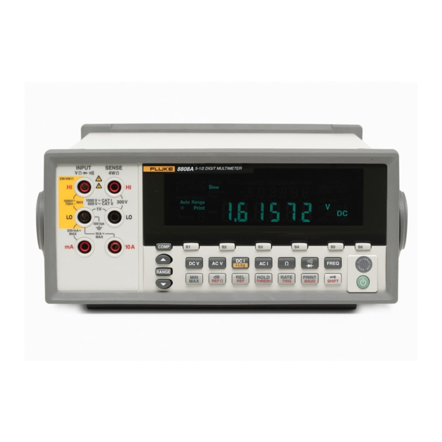
Introduction and Specifications Introduction Introduction The Fluke 8808A Digital Multimeter (hereafter referred to as the Meter) is a 5-1/2 digit dual-display multimeter designed for bench-top, field service, and system applications. The multiple measurement functions, plus the RS-232 remote interface, make the Meter an ideal candidate for precision manual measurements and use in automated systems. -
Page 12: Symbols
Recycle Do not dispose of this product as Static awareness. Static discharge unsorted municipal waste. Go to can damage parts. Fluke’s website for recycling information. Measurement Category II is for Measurement Category I is for measurements performed on CAT II... - Page 13 Introduction and Specifications Safety Information • Inspect the Meter before using it. Do not use the Meter if it appears damaged. • Inspect the test leads before use. Do not use them if insulation is damaged or metal is exposed. Check the test leads for continuity.
-
Page 14: Description Of Iec 61010 Measurement Categories
8808A Calibration Manual • Before measuring current, check the Meter's fuses and turn OFF power to the circuit before connecting the Meter to the circuit. • When servicing the Meter, use only specified replacement parts. Description of IEC 61010 Measurement Categories... -
Page 15: Manual Set
Chapter 1 – Introduction and Specifications This chapter introduces the Fluke 8808A Digital Multimeter, describing its features, and accessories. This chapter also discusses use of the Calibration Manual and the various conventions used in describing the meter’s circuitry and presents a complete set of specifications. -
Page 16: Operating Instructions
8808A Calibration Manual Operating Instructions Full operating instructions are provided in the Fluke 8808A Users Manual. Reference to these instructions may be necessary during some of the procedures presented in this Calibration Manual. Accessories Table 1-2 lists the available accessories for the 8808A. -
Page 17: General Specifications
Introduction and Specifications General Specifications General Specifications Voltage 100V Setting ............90 V to 110 V 120V Setting ............. 108 V to 132 V 220V Setting ............. 198 V to 242 V 240V Setting ............. 216 V to 264 V Frequency............ -
Page 18: Remote Interfaces
8808A Calibration Manual Remote Interfaces RS-232C Warranty One year Electrical Specifications Specifications are valid for 5-½ digit mode and after at least a half-hour warm-up. DC Voltage Specifications Maximum Input ..........1000 V on any range Common Mode Rejection......... 120 dB at 50 or 60 Hz ±0.1% (1 kΩ unbalance) Normal Mode Rejection ........ - Page 19 Introduction and Specifications Electrical Specifications Input Characteristics Resolution Full-Scale Range Input Impedance (5-1/2 Digits) Slow Medium Fast 1 μV 10 μV 10 μV 1 MΩ ±2 % shunted by 200 mV 199.999 mV <100 pf 10 μV 100 μV 100 μV 1.99999 V 100 μV 1000 μV...
-
Page 20: Resistance
8808A Calibration Manual Resistance Specifications are for 4-wire resistance function, or 2-wire resistance with REL. If REL is not used, add 0.2 Ω for 2-wire resistance plus lead resistance. Measurement Method ........Current source referenced to LO input Max Lead Resistance (4-wire ohms) ....10 % of range per lead for 200 Ω, 2 kΩ ranges. 1 kΩ per lead on all other ranges. -
Page 21: Ac Current
Introduction and Specifications Electrical Specifications Uncertainty Temperature Coefficient/°C Range Outside 18 – 28 °C 90 days 1 year 23 °C ± 5 °C 23 °C ± 5 °C 200 μA 0.02 + 0.005 0.03 + 0.005 0.003 + 0.001 2 mA 0.015 + 0.005 0.02 + 0.005 0.002 + 0.001... -
Page 22: Frequency
8808A Calibration Manual Frequency Gate Time ............131 ms Measurement Method ........AC-coupled input using the ac voltage measurement function. Settling Considerations ........When measuring frequency after a dc offset voltage change, errors may occur. For the most accurate measurement, wait up to 1 second to allow input blocking RC time constant to settle. -
Page 23: General Maintenance
Chapter 2 General Maintenance Title Page Introduction......................2-3 General Maintenance Information ............... 2-3 Required Equipment..................2-3 Static Safe Handling ..................2-3 Cleaning ....................... 2-4 Storing and Shipping the Meter ................2-4 Power Considerations ..................2-4 Selecting the Line Voltage ................2-4 Replacing the Fuses.................. - Page 24 8808A Calibration Manual...
-
Page 25: Introduction
General Maintenance Introduction Introduction This chapter provides handling, cleaning, fuse replacement, and display test instructions for the Meter. General Maintenance Information The following sections describe how to maintain the Meter. Required Equipment Equipment required for calibration, troubleshooting, and repair of the Meter is listed in Table 3-1. -
Page 26: Cleaning
8808A Calibration Manual Cleaning XW Warning To avoid electric shock or damage to the Meter, never get water inside the Meter. W Caution To avoid damaging the Meter’s housing, do not apply solvents to the Meter. If the Meter requires cleaning, wipe it down with a cloth lightly dampened with water or a mild detergent. -
Page 27: Replacing The Fuses
General Maintenance Power Considerations Replacing the Fuses The Meter uses one fuse to protect the line-power input and two fuses to protect the current-measurement inputs. Line-Power Fuse The Meter has a line-power fuse in series with the power supply. Table 2-1 indicates the proper fuse for each of the four line-voltage selections. -
Page 28: Current-Input Fuses
8808A Calibration Manual Current-Input Fuses The 200 mA and 10 A inputs are protected by user-replaceable fuses. • The 200 mA input is protected by a fuse (F2) rated at 440 mA, 1000 V (fast blow), 10,000 A minimum breaking capacity. -
Page 29: If The Meter Does Not Turn On
See the “Fuse Replacement” section earlier in this chapter for instructions on changing the voltage setting. 5. Verify that the power-line fuse is good. If these steps don’t solve the problem, then contact Fluke for more help. See the “Contacting Fluke” section in Chapter 4 for contact information. Display Tests The display test consists of turning on all the display elements and checking what appears in the display with Figure 2-3. - Page 30 8808A Calibration Manual ffw008.eps Figure 2-3. Display Elements 5. Push the front-panel power button twice to clear the display test.
-
Page 31: Performance Verification And Calibration
Chapter 3 Performance Verification and Calibration Title Page Introduction......................3-3 Required Equipment .................... 3-3 Direct Voltage Verification.................. 3-4 Alternating Voltage Verification ................. 3-5 4-Wire Ohms Verification ................... 3-6 2-Wire Ohms Verification ................... 3-7 Direct Current Verification .................. 3-8 Alternate Current Verification ................3-10 Frequency Verification .................. - Page 32 8808A Calibration Manual...
-
Page 33: Introduction
Table 3-1. Required Test Equipment Function Instrument Type Model Comments Volts dc Calibrator Fluke 5700A Figure 3-1 4-wire short Fluke low thermal 4-wire Fluke PN 2653346 short or equivalent Volts ac Calibrator Fluke 5700A Figure 3-1 Amplifier Fluke 5725A Resistance... -
Page 34: Direct Voltage Verification
8808A Calibration Manual Direct Voltage Verification To verify the Volts dc function of the Meter, connect it to the calibrator as shown in Figure 3-1 and apply the voltages listed in Table 3-2, Connect 57X0A and 5725A Callibrator to the UUT as follows:... -
Page 35: Alternating Voltage Verification
Performance Verification and Calibration Alternating Voltage Verification Alternating Voltage Verification To verify the Volts ac function of the Meter, connect it to the test equipment as shown in Figure 3-1 and apply the voltage listed in Table 3-3. Table 3-3. Alternating Voltage Verification Steps Nominal Input 90-Day Test Limit 1-Year Test Limit... -
Page 36: 4-Wire Ohms Verification
8808A Calibration Manual 4-Wire Ohms Verification To verify the 4-Wire Ohms function of the Meter, connect it to the test equipment as shown in Figure 3-2 and apply the resistances listed in Table 3-4. Connect 57X0A and 5725A Callibrator to the UUT as follows:... -
Page 37: 2-Wire Ohms Verification
To verify the 2-Wire Ohms function of the Meter, connect it to the test equipment as shown in Figure 3-3 and apply the resistances listed in Table 3-5. Connect 57X0A and 5725A Callibrator to the UUT as follows: 8808A 57X0A INPUT... -
Page 38: Direct Current Verification
8808A Calibration Manual Table 3-5. 2-Wire Ohms Verification Steps (cont.) 90-Day Test Limit 1-Year Test Limit Nominal Range Input High High 1.9 MΩ 2 MΩ STD+0.00063 MΩ STD-0.00063 MΩ STD+0.00084 MΩ STD-0.00084 MΩ 0 MΩ 20 MΩ 0.0006 MΩ -0.0006 MΩ... -
Page 39: Direct Current Verification Steps
Performance Verification and Calibration Direct Current Verification Connect 57X0A and 5725A Callibrator to the UUT as follows: 8808A 57X0A INPUT SENSE 2W/4W 1000 V CAT I 1000V 300V 600 V CAT II 750V 500 V pk OUTPUT SENSE 200 mA 10 A Ω... -
Page 40: Alternate Current Verification
8808A Calibration Manual Table 3-6. Direct Current Verification Steps (cont.) 90-Day Test Limit 1-Year Test Limit Nominal Range Input High High 0.00040 A -0.00040 A 0.00040 A -0.00040 A 1.9 A 1.90135 A 1.89865 A 1.90192 A 1.89808 A -1.9 A -1.89865 A... -
Page 41: Frequency Verification
The Meter adjustment process can either be managed through the front panel of the Meter or through the RS-232 port. In addition, a completely automated procedure is available as a Fluke Met/Cal program. Front Panel Adjustments To put the Meter in the calibration mode, remove the CAL seal and press the Cal Enable button located on the bottom-right side of the front panel with a thin needle. -
Page 42: Adjustment Steps
8808A Calibration Manual Table 3-9. Adjustment Steps Step Func./Command Point Input Signal Description Volts DC: zero points using the 4-wire short 0 mV/0V 0 mV Zero point of VDC, all ranges Volts DC: Gains – Adjust using 5700A/5725A -199.9 mV -199.9 mV... - Page 43 Performance Verification and Calibration Adjustment (Calibration) Table 3-9. Adjustment Steps (cont.) Step Func./Command Point Input Signal Description 1 V@1 kHz Gain of VAC, 20 V range 10 V 10 V@1 kHz 15 V 15 V@1 kHz 19.99 V 19.99 V@1 kHz 10 V 10 V@1 kHz Gain of VAC, 200 V range...
- Page 44 8808A Calibration Manual Table 3-9. Adjustment Steps (cont.) Step Func./Command Point Input Signal Description OHMS 10 Ω 10 Ω, 4Wire Gain of OHMS, 20 kΩ range 5k Ω, 4Wire OHMS 5 kΩ OHMS 10 kΩ 10 kΩ, 4Wire OHMS 15 kΩ...
- Page 45 Performance Verification and Calibration Adjustment (Calibration) Table 3-9. Adjustment Steps (cont.) Step Func./Command Point Input Signal Description 0.5 A 0.5 A@500 Hz Gain of AAC, 10 A range 2 A@500 Hz 5 A@500 Hz 10 A 10 A@500 Hz Current DC: zero points – Adjust with 5700A in standby or disconnected 0 μA/0 mA/0 A Open, no connection Zero point of ADC, all ranges...
-
Page 46: Calibration Points
8808A Calibration Manual in the primary display. Return to step 1 above and select the next function for calibration. Press Q to exit the calibration mode at any time. If a function has not been completely calibrated, a CAL ERROR will be displayed. -
Page 47: Rs-232 Calibration (Automatic)
Using an automated, computer-controlled procedure, the calibration and verification procedures can be performed on the Meter in less than 50 minutes. The 8808A MET/CAL procedure is available at no charge for MET/CAL Gold Support members from http://support.fluke.com/met-support-gold. - Page 48 8808A Calibration Manual {//vdc {0.0, -0.1999, -0.1, 0.1, 0.1999}, range 1 {0.0, -1.999, -1.0, 1.0, 1.999}, range 2 {0.0, -19.990, -10.0, 10.0, 19.990}, range 3 {0.0, -199.90, -100.0, 100.0, 199.9}, range 4 {0.0, -1000.0, -500.0, 500.0, 1000.0}, range 5 {//vac {0.0, 0.05, 0.10, 0.15, 0.1999},...
-
Page 49: List Of Replaceable Parts
Chapter 4 List of Replaceable Parts Title Page Introduction......................4-3 How to Obtain Parts..................... 4-3 How to Contact Fluke ..................4-3 Parts Lists......................4-4... - Page 50 8808A Calibration Manual...
-
Page 51: Introduction
Introduction Introduction This chapter contains an illustrated list of replaceable parts for the Fluke 8808A Digital Multimeter. Parts are listed by assembly and alphabetized by reference designator. Each assembly is accompanied by an illustration showing the location of each part and its reference designator. -
Page 52: Parts Lists
8845A-2009, REAR BOOT 2439161 MP10 FLUKE-8808A-8001, KEYPAD 2570286 MP11 FLUKE-8808A-2001, FRONT PANEL 2570247 MP12 8808A-2003, LENS 2570264 MP13 FLUKE-8808A-8002, FRONT PANEL DECAL 2570299 8845A-2001, TOP COVER 2439097 FLUKE-8808A-2005, WEDGE 2634240 8845A-2008, HANDLE 2439150 8845A-2010, FRONT BOOT 2439177 8808A, LABEL, CALIBRATION 3077525... - Page 53 List of Replaceable Parts Parts Lists MP3 H4 (4x) H2 (4x) H3 (5x) MP12 MP11 MP13 MP10 Front Panel Assembly ffw006.eps Figure 4-1. Front-Panel Assembly...
-
Page 54: Chassis Assembly
MP25 CT,9W,8808A,BULK 2716605 MP26 8808A-8003,REAR PANEL DECAL 2726188 TEST LEAD SET, 600V/1KV, PROBE-R/A PLUG, BLACK/RED (Not shown) 802980 GETTING STARTED, GUIDE, 8808A (Not shown) 2716412 CD-ROM, PROGRAMMER AND USERS MANUAL (Not shown) 2713002 2620A-4403, WIRE ASSY,GROUND 874099 8845A-4402, WIRE ASSY 2584378 CABLE ASSEMBLY, 6 COND, DB9(M), RECEPTACLE, 5.00 L... - Page 55 List of Replaceable Parts Parts Lists MP14, F3 MP16 MP15 H5 (2x) MP17 MP18 MP19 MP26 MP25 MP20 Chassis Assembly MP24 (2x) MP23 (4x) MP22 MP21 H8 (3x) ffw007.eps Figure 4-2. Chassis Assembly...
- Page 56 8808A Calibration Manual...
Need help?
Do you have a question about the 8808A and is the answer not in the manual?
Questions and answers