Siemens SIWAREX JB Instruction Manual
Aluminum housing
Hide thumbs
Also See for SIWAREX JB:
- Operating instructions manual (90 pages) ,
- Compact operating instructions (24 pages) ,
- Operating instructions manual (34 pages)
Table of Contents
Advertisement
Quick Links
Advertisement
Table of Contents

Related Manuals for Siemens SIWAREX JB


Summary of Contents for Siemens SIWAREX JB
- Page 1 SIWAREX JB Aluminum Housing Instruction Manual Edition 03/2006...
-
Page 2: Table Of Contents
4.1 Functional Data..................15 4.2 Device Version..................15 4.3 Explosion Protection ................15 4.4 Electromagnetic Compatibility..............16 4.5 Dimensions ....................16 Care and Maintenance................17 Ordering Data ..................18 SIWAREX JB junction box in aluminum housing – Instruction Manual A5E00400544B... -
Page 3: Warning And Safety Terms
We are grateful for any suggestions for improvement. Siemens AG Automation and Drives Process Instrumentation and Analytics © Siemens AG 2006 D-76181 Karlsruhe Subject to technical changes SIWAREX JB junction box in aluminum housing – Instruction Manual A5E00400544B... -
Page 4: General
The content of this product documentation is not part of an earlier or existing agreement, promise or legal relationship and neither shall it change any of these. All Siemens obligations ensue from the respective contract of sale which also contains the full and exclusively valid liability regulation. -
Page 5: Technical Description
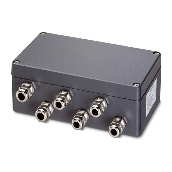
1 Technical Description 1.1 Area of Application The SIWAREX JB junction box made of die-cast aluminum serves for connecting load cells with the weigh module. Up to four load cells can be connected in parallel in one junction box (fig. 1-1). Another junction box must be connected in parallel by a cross connection in case of more than 4 load cells (fig. -
Page 6: System Configuration
Technical Description 1.3 System Configuration The SIWAREX JB junction box is used in technical weighing systems for parallel connection of up to four wire strain gage load cells. If more than four load cells are to be connected to a weigh module, several junction boxes can be connected to each other by cross connections. -
Page 7: Installation/Assembly
2 Installation/Assembly 2.1 Installation The SIWAREX JB junction box may only be installed and connected by qualified personnel. 2.2 Connection The connection of load cells with 4 or 6-wire technique to a weigh module must be made according to the wiring diagrams in fig. 2-1 or fig. 2-2, page 8. Analogously, several load cells are also connected in parallel. - Page 8 Revision 03.06 Installation/Assembly Fig. 2-1 Load cell connection by 4-wire technique Fig. 2-2 Load cell connection by 6-wire technique SIWAREX JB junction box in aluminum housing – Instruction Manual A5E00400544B...
- Page 9 Revision 03.06 Installation/Assembly Fig. 2-3 Terminal block Fig. 2-4 Shield in the screw cable gland SIWAREX JB junction box in aluminum housing – Instruction Manual A5E00400544B...
- Page 10 = Load cell Input = Output to weigh module, to the Ex barrier or other junction box EPB = Equipotential bonding connection Fig. 2-5 Pinout of the screw cable glands SIWAREX JB junction box in aluminum housing – Instruction Manual A5E00400544B...
-
Page 11: Installation
Installation/Assembly 2.3 Installation The SIWAREX JB junction box can be mounted in any position. It should preferably be mounted horizontally. It is fixed with four M6 cylinder head screws. The dimensions of the fastening holes are shown in fig. 2-6, page 12. - Page 12 Revision 03.06 Installation/Assembly Fig. 2-6 Dimensions of the fastening holes SIWAREX JB junction box in aluminum housing – Instruction Manual A5E00400544B...
-
Page 13: Spring Terminal Connection Technique
0.08 to 1 mm / AWG 28 to 18: Fine wire with gas-tight crimped on end sleeves. SIWAREX JB junction box in aluminum housing – Instruction Manual A5E00400544B... -
Page 14: Commissioning
3 Commissioning Since the junction box is a passive component the instruction manual of the weigh module should be observed primarily for commissioning. SIWAREX JB junction box in aluminum housing – Instruction Manual A5E00400544B... -
Page 15: Technical Data
DIN EN 60079-14 (VDE0165) or DIN EN1127-1. EC Type Examination Certificate All work on electrical circuits for systems where there is a risk of explosion must be performed by qualified personnel. SIWAREX JB junction box in aluminum housing – Instruction Manual A5E00400544B... -
Page 16: Electromagnetic Compatibility
Revision 03.06 Technical Data 4.4 Electromagnetic Compatibility The SIWAREX JB junction box meets the following EMC requirements: • EN 61326: 1999 • EN 45501: 1992 • NAMUR NE21: 2004 To maintain EMC, e.g. • an EMC-compatible laying of cables (also inside cabinets!) must be observed. -
Page 17: Care And Maintenance
The junction box is maintenance-free. The clamping force of the spring terminals always remains constant. CAUTION Do not apply the jet of a high-pressure cleaner directly to the junction box. SIWAREX JB junction box in aluminum housing – Instruction Manual A5E00400544B... -
Page 18: Ordering Data
6. Ordering Data Name: Order number: SIWAREX JB junction box – aluminum housing 7MH4 710-1BA SIWAREX JB junction box in aluminum housing – Instruction Manual A5E00400544B...
Need help?
Do you have a question about the SIWAREX JB and is the answer not in the manual?
Questions and answers