Lennox CLIMATIC 50 User Manual
Chiller & heat pump including neosys range
Hide thumbs
Also See for CLIMATIC 50:
- User manual (84 pages) ,
- Installation operating & maintenance manual (19 pages) ,
- Installation operating & maintenance manual (78 pages)

Related Manuals for Lennox CLIMATIC 50


Summary of Contents for Lennox CLIMATIC 50
- Page 1 User manual CLIMATIC™ 50 - CHILLERS Providing indoor climate comfort CL50-CHILLERS-IOM_Cust0808-E...
- Page 2 All the technical and technological information contained in this manual, including any drawing and technical descriptions provided by us, remain the property of Lennox and must not be used (except in operation of this product), reproduced, issued to or made available to third parts without the prior written agreement of Lennox.
-
Page 3: Table Of Contents
TABLE OF CONTENT Page Introduction......................3 Wiring connections ....................4 Configuration ......................8 Scheduling – Clock setting ..................9 Customized input/output..................11 Standard input/output .....................14 Configuration of the BM50 plan address..............15 Allocation of displays to the BM50 .................16 DC50 comfort display .....................17 DS50 menu tree .....................24 Error codes alarms ....................34 CLIMATIC™50 –... -
Page 4: Introduction
Warning Any parameter modification should be carried out by trained and licensed competent technician. Before start-up or restart of a unit controlled by Climatic 50, it is mandatory to check adequacy between Climatic 50 and the unit with its options. -
Page 5: Wiring Connections
WIRING CONNECTIONS IMPORTANT WARNING Any wiring modification on the CLIMATIC™50 must be done by Lennox technician or employees having valid electrical qualification and authorisation. For any modification of wiring on the 24V supply or on 4-20mA sensor, check the polarity prior to apply the power. - Page 6 Cable length up to 500m: LiYCY-P (0.34 mm ²), 2 pairs with general shield. The cable length should not exceed 500m. For a better electromagnetic protection, Lennox recommends the use of LiYCY-P cable. CONNECTION ON DT50 DERIVATOR...
- Page 7 WIRING CONNECTIONS Ferrites Protection of Display To avoid the appearance of disturbances HF, which can cause the destruction of components in the displays, you must equip the cable with a ferrite when installing it (provided by Lennox). FERRITE N°1 Remote...
- Page 8 Cable length up to 1000m: LiYCY-P (0.34 mm ²), 2 pairs with general shield. The cable length should not exceed 1000m. For a better electromagnetic protection, LENNOX recommends the use of LiYCY-P cable. CLIMATIC™50 – Chiller / Heat Pump – Customer version Page 7 CL50-CHILLER-IOM_CUST-0808-E...
-
Page 9: Configuration
(3851), (3852), (3853), (3854) Parametric analog input configuration of extension board BE50 1 to 4, (3861) Restore the standard Lennox settings or not (This parameter don’t modify the settings (38xx), CLIMATIC™50 – Chiller / Heat Pump – Customer version... -
Page 10: Scheduling - Clock Setting
SCHEDULING – CLOCK SETTING CLOCK SETTING Function Climatic™50 has a real time clock board, allowing dates and hours functionalities (weekly program, event recording,…). Description Menus (3121) to (3125) give the possibility of setting the internal clock. The day of the week is calculated by Climatic™50. For the countries of the Euro, the controller allows the automatic swing of the hour summer in hour winter and vice versa. - Page 11 SCHEDULING – CLOCK SETTING For each time zone, the set following set points following can be modified: DISPLAY DISPLAY LIST SET POINT BY ZONE Code CONFORT MAINTENANCE Change over control Cooling / Heating priority (3311) Water temperature Cooling Water T° Set point A (3321) Cooling Water T°...
-
Page 12: Customized Input/Output
6 digitals inputs set up by parameters (3851), (3852), (3853) and (3854), 4 analogical inputs (4-20mA or Lennox NTC temperature probe), set up with parameters (3861), (3862), (3863) and (3864). Description The wiring connection between the BM.50 and the BE.50 is described on the following figure:... - Page 13 CUSTOMIZED INPUT/OUTPUT DIGITAL INPUTS – DRY CONTACTS Electrical characteristics: 24Vac or 24Vdc, 50/60Hz. The corresponding between the connectors and the settings is: (3841) Setting for the digital output on the connector BM50-J8-ID13, (3842) Setting for the digital output on the connector BM50-J8-ID14, (3843) ...
- Page 14 The 4-20mA signal sent to the unit is linearly converted using a -5K to +5K range of temperature set point. Free temperature probe connection: Lennox NTC sensor: The measured value will be displayed on following addresses (2171), (2172), (2173) or (2174). CLIMATIC™50 – Chiller / Heat Pump – Customer version...
-
Page 15: Standard Input/Output
STANDARD INPUT/OUTPUT Function The Climactic™50 main board (BM.50) offers free dry contacts to control the unit. These free dry contacts are connected directly to terminals (orange colour) identified as follow: [824 - 825] : 24V relay customers power supply (Option), ... -
Page 16: Configuration Of The Bm50 Plan Address
CONFIGURATION OF THE BM50 pLAN ADDRESS Function It may be necessary to change the address of the BM50 card on the pLan network – mainly in the case of Master/Slave installation. To do this, use the following procedure: Description Set the address of the DS/DC50 display to 0: Sds.1 ... -
Page 17: Allocation Of Displays To The Bm50
ALLOCATION OF DISPLAYS TO THE BM50 Function Ensure there is a good connection between the BM50 and its displays Description For each Climatic™50 card the following setting must be made using the DS50. Disconnect the pLan bus at J10 and J11 and connect the DS50, directly to J10 of the BM50; ... -
Page 18: Dc50 Comfort Display
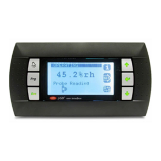
DC50 COMFORT DISPLAY Function This display is connected remotely; it is intended for users with no technical knowledge. This display gives access to general operating data of the unit. It does not give access to detailed operating data. It can be used to set or change the programming of the various time periods and the temperature set point for each period. It also has the ability to set a 3 hours override and force an unoccupied mode, or any other different time periods, for a maximum of 7 days. -
Page 19: Main Screen
DC50 COMFORT DISPLAY Sdc.2 The Sdc.2 screen appears. If after 5 seconds the display is not correct; Return configuration mode pressing buttons simultaneously for at least 5 seconds until the Sdc.1 screen appears. to position the cursor over the ‘Setting’ line Press button ... - Page 20 DC50 COMFORT DISPLAY In this example, the unit will remain in when confirmed until midnight on Thursday. the unoccupied period on Tuesday It will revert back to the main screen after 15 seconds without any activity. Clock Menu These screens are used to display and change the time and date on the BM50. Sdc.6 From the main screen, press the ‘clock’...
- Page 21 DC50 COMFORT DISPLAY CLIMATIC™50 – Chiller / Heat Pump – Customer version Page 20 CL50-CHILLER-IOM_CUST-0808-E...
- Page 22 DC50 COMFORT DISPLAY Sdc.9.b From the Sdc.9.a screen; press the ‘Prg’ button Screen Sdc.9.b displays the water set points. set the desired temperature for period A and confirm with With button button Press the button ‘Clk’ to change the time period. Repeat the procedure for each time period (Z:A, Z:B, Z:C, Uno).
- Page 23 DC50 COMFORT DISPLAY Start/stop From the main screen, press the button Sdc.13 The Sdc.13 screen appears. To stop the unit: Sdc.14 s et the value to ‘Yes’ and confirm with button With button The unit stops and the Sdc.14 screen appears WARNING: Switching off the unit disables all the safety devices Pressing the ‘Esc’...
- Page 24 DC50 COMFORT DISPLAY Navigation in the screens Main menu (0000) The four digits in brackets indicate the number of the current menu. The two digits beside the brackets indicate the pLan number of the selected card. The display on the right indicates the period of operation and the current time conditions.
-
Page 25: Ds50 Menu Tree
DS50 MENU TREE Menu Item Menu Item Menu Item Menu Item UNIT MAX FACTORY 1000 ALARM 2000 DATA 2100 GENERAL 2110 TEMPERATURE 2111 OUTSIDE °C 2112 INLET °C 2113 OFFSET °C 2114 OUTSIDE °C 2120 CIRCUIT 1 2121 T°SUPERHEAT °C 2122 T°COND °C... - Page 26 DS50 MENU TREE Menu Item Menu Item Menu Item Menu Item UNIT MAX FACTORY 2322 STATUS List 2323 SW STATE OFF/ON 2324 SW RELAY OFF/ON 2325 SW HP OFF/ON 2326 SW LP OFF/ON 2327 VALVE OFF/ON 2328 RUN TIME Hour 2330 CIRC.1.COMP.3 2331...
- Page 27 DS50 MENU TREE Menu Item Menu Item Menu Item Menu Item UNIT MAX FACTORY 2520 CIRCUIT 2 2521 CONFIG. List 2522 STATUS List 2523 SW STATE OFF/ON 2524 MODE List 2525 VALUE °C 2526 MAXIMUM 2527 CAPACITY 2600 OPTION 2610 COOL 2611 CONFIG.
- Page 28 BMS ADDRESS TABLES ModBus, Trend, BACnet & Carel LOGICAL DATA Description DS50 @ (hexa) @ (deci) R/W Unit [On/Off] General On/Off of the unit 3111 [Off] Unit OFF - [On] Unit ON [Reset] Discharges the safety measures of the unit 3113 [BMS] BMS On/Off of the unit 3112...
- Page 29 BMS ADDRESS TABLES [On/Off] Compressor 3, Circuit 1 2336 2317 [On/Off] Compressor, Heat pump, Circuit 1 [On/Off] Compressor 1, Circuit 2 2346 [On/Off] Compressor 2, Circuit 2 2356 2366 [On/Off] Compressor 3, Circuit 2 [On/Off] Compressor, Heat pump, Circuit 2 2347 not used not used...
- Page 30 BMS ADDRESS TABLES ANALOGIC DATA DS50 @ (hexa) @ (deci) Unit Description [ BMS ] Activation of the control by a computer or an automat. 3934 1 = 1 s Mode BMS is activated if this value is different from zero. This value is decreased every second.
- Page 31 BMS ADDRESS TABLES 10 = 1.0°c [Temperature] Outlet, Water 2113 2122 10 = 1.0b [Temperature] High, Circuit 1 10 = 1.0b 2123 [Temperature] Low, Circuit 1 10 = 1.0b [Temperature] High, Circuit 2 2132 2133 10 = 1.0b [Temperature] Low, Circuit 2 10 = 1.0b [EEV] Saturated evaporation temperature, Circuit 1 2124...
- Page 32 BMS ADDRESS TABLES [Alarm] bit.0 = Flow switch bit.1 = High Temperature, Outlet bit.2 = Low Temperature, Inlet bit.3 = Low Temperature, Outlet bit.4 = High Temperature, Inlet bit.5 = Pump, 1 bit.6 = Pump, 2 10 = 1.0 bit.7 = Real Time Clock bit.8 = BE50 bit.9 = not used bit.10 = Probes &...
- Page 33 BMS ADDRESS TABLES LonWorks LOGICAL DATA BM50 Type Name NV Type NV Direction Index DS50 Description Index I_Sp_On_Unit input 3111 [On / Off] Unit O_Sp_On_Unit output I_Sp_Reset input [Reset] Discharges the safety measures of the unit 3113 O_Sp_Reset output I_Sp_Unoc input [BMS] Activation of the Inoccupation mode [Off] 3925...
- Page 34 BMS ADDRESS TABLES INTEGER DATA Type Index Name NV Type NV Direction Index Description DS50 [ BMS ] Activation of the control by a computer or an I_Sp_BMS_Dog input 3934 automat - mode BMS is activated if this value is different O_Sp_BMS_Dog output from zero, This value is decreased every second...
-
Page 35: Error Codes Alarms
ERROR CODES ALARMS Flow Rate Water Evaporator Electrical Heater(s) High Outlet Water Temperature Low Inlet Water Temperature Low Outlet Water Temperature High Inlet Water Temperature Pump Flow Pump 1 Pump 2 Clock card BE50 Temperature Probe Water Inlet Temperature Probe Outside Temperature Probe Water Outlet Temperature Probe Water Heat Recovery Inlet Temperature Probe Water Heat Recovery Outlet... - Page 36 BELGIUM, LUXEMBOURG PORTUGAL Due to Lennox’s ongoing commitment to quality, www.lennoxbelgium.com www.lennoxportugal.com the Specifications, Ratings and Dimensions are subject to change without notice and without incurring liability. CZECH REPUBLIC RUSSIA Improper installation, adjustment, alteration, www.lennox.cz www.lennoxrussia.com service or maintenance can cause property damage or personal injury.
Need help?
Do you have a question about the CLIMATIC 50 and is the answer not in the manual?
Questions and answers