Table of Contents
Advertisement
Advertisement
Table of Contents

Related Manuals for Lennox CLIMATIC 60


Summary of Contents for Lennox CLIMATIC 60
- Page 1 User manual CLIMATIC™ 60 Aircooled chillers MUL41E-0610/06-2011...
-
Page 3: Table Of Contents
CLIMATIC™ 60 – AIRCOOLED CHILLERS TABLE OF CONTENTS INTRODUCTION ........................2 OVERVIEW ..........................2 SCHEDULING ZONE ......................... 3 SCHEDULING MODE ........................ 4 SCHEDULING ZONE ANTICIPATION ..................5 CHANGEOVER HEAT / COOL ....................6 FREE INPUT / OUTPUT ......................8 WATER EVAPORATOR ......................12 PUMP EVAPORATOR MANAGMENENT ................ -
Page 4: Introduction
1 - INTRODUCTION 1.1 - CONTROLLER CLIMATIC™60 The new generation of microprocessor based control, CLIMATIC™ 60 may be fitted to the Lennox Chiller or Heat pump range. It inherits 20 years of technology and field operating experience from its predecessors the CLIMATICTM1 and CLIMATICTM2 and CLIMATICTM50. -
Page 5: Scheduling Zone
CLIMATIC™ 60 – AIRCOOLED CHILLERS 3 - SCHEDULING ZONE 3.1 - Function The CLIMATIC™ 60 is provided by a real time clock which offers solutions to specify a weekly schedule. 3.2 - Description The CLIMATIC™ 60 schedule manages up to 7 distinct clock zones per day from 00h00 to 24h00 and from Monday to Sunday. -
Page 6: Scheduling Mode
CLIMATIC™ 60 – AIRCOOLED CHILLERS 4 - SCHEDULING MODE 4.1 - Function The CLIMATIC™ 60 is able to control different mode for each zone in order to optimise the operating of the unit. 4.2 - Description The CLIMATIC™ 60 can manage up to 4 different modes. 4.3 - Settings The different settings to adjust the scheduling mode are available in the menu: •... -
Page 7: Scheduling Zone Anticipation
CLIMATIC™ 60 – AIRCOOLED CHILLERS 5 - SCHEDULING ZONE ANTICIPATION 5.1 - Function The CLIMATIC™ 60 allows the start up of the unit before the pre-specifyd hour of the first zone (Zone 1) of the day. 5.2 - Description This function is able to start the unit in zone 1 earlier if the outdoor temperature is under a specify threshold. The typical application is to start the unit in heating mode if the weather is too cold compare to the actual season. -
Page 8: Changeover Heat / Cool
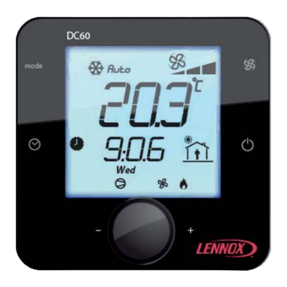
CLIMATIC™ 60 – AIRCOOLED CHILLERS 6 - CHANGEOVER HEAT / COOL 6.1 - Function The CLIMATIC™ 60 control the changeover mode (for reversible units only) to specify the appropriate demand on heat water or chilled water production. 6.2 - Description The changeover can also be pre-specify according to the scheduling and can take different mode for each schedule mode (A, B, C, D, and BMS). - Page 9 CLIMATIC™ 60 – AIRCOOLED CHILLERS Terminal DC60: The changeover mode (cool / heat) can be modified by the terminal DC60 by pressing the “mode” button. Heat Cool Auto Dead zone When the “Auto” mode is selected, the icon “Cool” or “Heat” is displayed to signal the actual operating mode. Due to the communication delay, after pressing the “mode”...
-
Page 10: Free Input / Output
CLIMATIC™ 60 – AIRCOOLED CHILLERS 7 - FREE INPUT / OUTPUT 7.1 - Function The CLIMATIC™ 60 have free input / output on the main board BM60 and the expansion board BE60 to offer some possibilities to customize input / output for remote control of the unit. 7.2 - Description The number of the free customized input / output is: •... - Page 11 CLIMATIC™ 60 – AIRCOOLED CHILLERS Analog input The 4 analog inputs can be used as NTC probe (-50T90 °C; R/T 10 KΩ at 25 °C) or 4/20mA (Impedance = 100Ω) current signal. They are configurable by pair B1-B2 and B3-B4. The configuration of the type of the input is automatically set by the CLIMATIC™...
- Page 12 CLIMATIC™ 60 – AIRCOOLED CHILLERS Digital output The 4 digital outputs are dry contacts and the maximum commutable power is 2000VA, 250Vac. The digital output can be configurable to be used as one of these items: Not set, General alarm (alarm minor), General fault (alarm major), General alarm on circuit 1, General alarm on circuit 2,...
- Page 13 CLIMATIC™ 60 – AIRCOOLED CHILLERS 7.3 - Settings The different settings to configure the custom I/O are available in the menu: • (3131): Setting for the digital output on the connector BM60-J14-NO7, • (3132): Setting for the digital output on the connector BE60-J5-NO1, •...
-
Page 14: Water Evaporator
CLIMATIC™ 60 – AIRCOOLED CHILLERS 8 - WATER EVAPORATOR 8.1 - Function The CLIMATIC™ 60 controls the chilled or heat temperature according to the specifyd set point. The desired set point can be set by different solutions: 8.2 - Description The CLIMATIC™... - Page 15 CLIMATIC™ 60 – AIRCOOLED CHILLERS 8.2.4 - External second set point In this case the actual set point is specifyd by one of the 2 set point (3238) and (3239). The final set point depends on the status of the digital dry contact allocated to this function. 8.2.5 - External current 4/20mA offset In this case the set point is set by one of the previous solution and can be adjust with an offset of +/- 1.0°C.
- Page 16 CLIMATIC™ 60 – AIRCOOLED CHILLERS 8.3 - Settings The different settings to adjust the water evaporator set points are available in the menu: 8.3.1 - COOLING MODE • (3236): Minimum of outside air temperature corresponding to the water evaporator set point (3238) (used only for dynamic set point), •...
- Page 17 CLIMATIC™ 60 – AIRCOOLED CHILLERS 8.4 6 Control The Climactic™60 adjusts and hold the fluid outlet temperature as close as possible to the set point, by controlling the number of compressor stages depending on the thermal load of the system. The controller calculates constantly the required capacity to reach the temperature set point.
-
Page 18: Pump Evaporator Managmenent
CLIMATIC™ 60 – AIRCOOLED CHILLERS 9 - PUMP EVAPORATOR MANAGEMENT 9.1 - Function The CLIMATIC™ 60 offers in option a solution to manage a single or double evaporator pump(s). 9.2 - Description In case of double pumps the CLIMATIC™ 60 can manage various possibilities of operating of the pumps. 9.2.1 - Priority to the pump 1 The CLIMATIC™... -
Page 19: Pump Evaporator Flow Control
CLIMATIC™ 60 – AIRCOOLED CHILLERS 10 - PUMP EVAPORATOR FLOW CONTROL 10.1 - Function The ClimaticTM60 offers the possibility to have a flow control in option. 10.2 - Description There is up to 4 modes to manage the evaporator water flow. 10.2.1 - Fix speed The CLIMATIC™... - Page 20 CLIMATIC™ 60 – AIRCOOLED CHILLERS 10.2.3 - Fix delta P The CLIMATIC™ 60 maintains a fix delta of pressure according to the transducers (in and out) on the pump. The delta of pressure desired is customized in the menu (3375). 10.2.4 - Fix Out P The CLIMATIC™...
-
Page 21: Pump Condenser Managmenent
CLIMATIC™ 60 – AIRCOOLED CHILLERS 11 - PUMP CONDENSER MANAGMENENT 11.1 - Function The CLIMATIC™ 60 offers in option a solution to manage a single or double condenser pump(s). 11.2 - Description In case of double pumps the CLIMATIC™ 60 can manage various possibilities of operating of the pumps. 11.2.1 - Priority to the pump 1 The CLIMATIC™... -
Page 22: Pump Condenser Flow Control
CLIMATIC™ 60 – AIRCOOLED CHILLERS 12 - PUMP CONDENSER FLOW CONTROL 12.1 - Function The CLIMATIC™ 60 offers the possibility to have a flow control in option. 12.2 - Description 12.2.1 - Fix flow The CLIMATIC™ 60 maintains a fix flow according to the maximum flow desired. The flow is set to the minimum flow desired only when none compressor is running. - Page 23 CLIMATIC™ 60 – AIRCOOLED CHILLERS 12.2.3 - Fix delta P The CLIMATIC™ 60 maintains a fix delta of pressure according to the transducers (in and out) on the pump. The delta of pressure desired is customized in the menu (3385). 12.2.4 - Fix Out P The CLIMATIC™...
- Page 24 CLIMATIC™ 60 – AIRCOOLED CHILLERS 12.3 - Settings The different settings to adjust the flow control are available in the menu: • (3382): Type of flow control, • (3384): Delta of temperature desired on the evaporator water (Outlet - Inlet), •...
-
Page 25: Compressor
CLIMATIC™ 60 – AIRCOOLED CHILLERS 13 - COMPRESSOR 13.1 - Function The CLIMATIC™ 60 manages the compressor(s) according to the outlet temperature demand and engages the number of compressor calculated to reach the water set point. 13.2 - Description The CLIMATIC™ 60 offers possibilities to disable some compressor(s) on the circuit. Note this opportunity can be also done by dry contact (Refer to the “Free input/output”... - Page 26 CLIMATIC™ 60 – AIRCOOLED CHILLERS The compressor is subject to various operating time in order to prevent from damage operating. • The minimum ON time of the compressor is fixed to 1 minute, • The minimum OFF time of the compressor is fixed to 1 minute, •...
-
Page 27: Condenser Fan
CLIMATIC™ 60 – AIRCOOLED CHILLERS 14 - CONDENSER FAN 14.1 - Function The CLIMATIC™ 60 is used to maintain the high pressure as stable as possible in order to increase the performance of the unit. 14.2 - Description The CLIMATIC™ 60 has 2 different fan managements according to the type of unit: 14.2.1 - Ecolean unit (without fan speed inverter) The CLIMATIC™... - Page 28 CLIMATIC™ 60 – AIRCOOLED CHILLERS 14.3 - Settings The different settings to adjust the condensing control are available in the menu: • (3546): Condensing set point temperature. Page 26 MUL41E-0610/06-2011...
-
Page 29: Fan Smart Accoustic Systemtm
CLIMATIC™ 60 – AIRCOOLED CHILLERS 15 - FAN SMART ACOUSTIC SYSTEM™ 15.1 - Function The CLIMATIC™ 60 controls the fan speed limit by the Smart Acoustic System™ which allows progressive adaptation of the unit to the building load while respecting the noise level constraints and the operating limits. 15.2 - Description The maximum sound level and the fan strategies can be adjusted according to the schedule mode in order to benefit from the different modes “High performance”, “Quiet”... - Page 30 CLIMATIC™ 60 – AIRCOOLED CHILLERS 15.2.2 - “Quiet++” This mode is similar to the “Quiet” mode except that the fan speed limit or the high speed is never unlocked. In case of condensing temperature too high, the CLIMATIC™ 60 will unload a compressor to prevent from HP security.
- Page 31 CLIMATIC™ 60 – AIRCOOLED CHILLERS 15.3 - Settings The different settings to adjust the acoustic mode are available in the menu: • (3544): Acoustic mode, • (3545): Maximum sound level noise (except for fan with low / high speed). MUL41E-0610/06-2011 Page 29...
-
Page 32: Coil Defrost
CLIMATIC™ 60 – AIRCOOLED CHILLERS 16 - COIL DEFROST 16.1 - Function The CLIMATIC™ 60 manages defrost procedure to avoid ice on the evaporator coil in heating pump mode (winter season). 16.2 - Description To avoid the icing of the external air exchanger during winter operating, it’s necessary to reverse the refrigerant cycle. -
Page 33: Water Condenser
CLIMATIC™ 60 – AIRCOOLED CHILLERS 17 - WATER CONDENSER /*******************/ UNDER CONSTRUCTION /*******************/ MUL41E-0610/06-2011 Page 31... -
Page 34: Freecooling
CLIMATIC™ 60 – AIRCOOLED CHILLERS 18 - FREECOOLING 18.1 - Function The freecooling option ensures to reduce the electrical consumption using the outside air temperature to produce cool water. 18.2 - Description The freecooling uses water coil with helicoids fans control by the CLIMATIC™ 60. The freecooling has a higher priority face to the compressors. -
Page 35: Electrical Heater
CLIMATIC™ 60 – AIRCOOLED CHILLERS 19 - ELECTRICAL HEATER 19.1 - Function The electrical heater option is an additional heating capacity to help the heat pump to reach the set point during hard winter period. 19.2 - Description The electrical heater option has both utilisations: 19.2.1 - Antifreeze heater In this case, the heater is used to prevent the evaporator water from antifreeze. -
Page 36: Power Factor Corrector
CLIMATIC™ 60 – AIRCOOLED CHILLERS 20 - POWER FACTOR CORRECTOR 20.1 - Function The power factor correction is an additional capacitor bank to compensate the apparent power energy. 20.2 - Description The CLIMATIC™ 60 controls the status of the circuit breaker to inform (generate an alarm) in case of short circuit in the capacitor bank. -
Page 37: Master / Slave
CLIMATIC™ 60 – AIRCOOLED CHILLERS 21 - MASTER / SLAVE 21.1 - Function The CLIMATIC™ 60 offers possibilities to connect up to 8 units to allow relationship between each unit in order to perform the system. The pLAN bus is connected to Climatic™60 on the J8 connector of board BM60. A star connection is not recommended. -
Page 38: Display Dc60
CLIMATIC™ 60 – AIRCOOLED CHILLERS 22 - DISPLAY DC60 22.1 - Function The DC60 display is customized for the user to show a global operating overview of the unit and allow access to some settings. In case of remote display, the cable length should not exceed 30m. 22.2 - Description The DC60 terminal displays various status of the unit and offers the possibility to override the initial operating of the unit. - Page 39 CLIMATIC™ 60 – AIRCOOLED CHILLERS 22.2.13 - Schedule zone specify the schedule operating zone. Mode A, Mode B, Mode C, Mode D, Mode GTC. The terminal DC60 also displays the status of the main component of the unit in the status area. The icons can take different appearance according to the status of the component.
-
Page 40: Display Ds60
CLIMATIC™ 60 – AIRCOOLED CHILLERS 23 - DISPLAY DS60 23.1 - Function The DS60 terminal is a plug and play display, designed for maintenance and service people who want to access to advanced functionalities. 23.2 - Description The terminal address must be assign to establish the communication with the CLIMATIC™ 60. The procedure to configure the DS60 is: 1) Press the buttons “↓”, “↑”, “←”... - Page 41 CLIMATIC™ 60 – AIRCOOLED CHILLERS 7) The following screen describe the type of connection used. Set the display as a Private “Pr” terminal. The other terminals (Trm2 and Trm3) are not used. So their addresses must be adjusted to “None”. Finally confirm the modifications and swapping the text “No”...
- Page 42 CLIMATIC™ 60 – AIRCOOLED CHILLERS To reset the current active alarm(s) press the “ALARM” key. The menu is organised in arborescence tree with submenus. The actual menu is identified by the number in parentheses in the top left corner of the screen. The “↓”...
- Page 43 CLIMATIC™ 60 – AIRCOOLED CHILLERS The submenus contain 2 types of data: The read only data (like a temperature probe for example) and the read/write setpoints (like the cooling water setpoint for example). The data are identified by a cursor symbol “>” whereas the setpoint are identify by a symbol “>>”.
-
Page 44: Bms
CLIMATIC™ 60 – AIRCOOLED CHILLERS 24 - BMS 24.1 - Function BMS (Building Management Systems) are systems for the integrated management of all the technological functions of a building, including access control, safety, fire detection, lighting, intelligent elevators, and Air-Conditioning. The resulting advantages of such solutions as simpler and more efficient management of the building from a single control station, reduction in running costs, possibility of statistical analysis of all data, immediate identification of and response to faults and alarms, amply justify the little extra cost of the Air-Conditioning unit BMS connectable. - Page 45 CLIMATIC™ 60 – AIRCOOLED CHILLERS LENNOX units implement Modbus slave protocol with the following settings: Serial Line RS485 (EIA/ TIA - 485 Standard) Transmission Mode RTU (Remote Terminal Unit) Baudrate 120019200 Bauds Data bits 8 bits Parity None Stop bits 1 bit 24.3 - Settings...
-
Page 46: Inputs / Outputs Climatic Boards
CLIMATIC™ 60 – AIRCOOLED CHILLERS 25 – INPUTS / OUTPUTS CLIMATIC BOARDS 25.1 – Digital inputs and digital outputs ELECTRICAL INPUTS/OUTPUTS MAPPING EAC/EAR UNITS CLIMATIC™ 60 Main Board Digital Input Digital Output J4.ID1 Compressor J12.NO1 Compressor 1 J4.ID2 J12.NO2 High pressure safety Compressor 2 J4.ID3 Condenser fan... - Page 47 CLIMATIC™ 60 – AIRCOOLED CHILLERS 25.3 – Serial port ELECTRICAL INPUTS/OUTPUTS MAPPING EAC/EAR UNITS CLIMATIC™ 60 Main Board SERIAL PORT Opt° Unit BMS Customer Bus Unit DS60 Terminal Display Unit CL60 external Bus Unit CL60 internal Bus MUL41E-0610/06-2011 Page 45...
-
Page 48: Setting List
CLIMATIC™ 60 – AIRCOOLED CHILLERS 26 - SETTINGS LIST Level 1 Item Level 2 Item Level 3 Item Level 4 Item R/W/Z Unit Description 1000 Alarm 1100 1110 1111 2000 User 2100 Unit 2110 General 2111 On/Off General On/Off User Unit General 2112... - Page 49 CLIMATIC™ 60 – AIRCOOLED CHILLERS Level 1 Item Level 2 Item Level 3 Item Level 4 Item R/W/Z Unit Description User Unit 2140 Schedule Time 2141 Time Z0 Start time zone 0 User Unit Schedule Time 2142 Time Z1 Start time zone 1 User Unit Schedule Time...
- Page 50 CLIMATIC™ 60 – AIRCOOLED CHILLERS Level 1 Item Level 2 Item Level 3 Item Level 4 Item R/W/Z Unit Description 21=Zone 6, 0=Not Set, 22=Mode A, 1=Alarm, 23=Mode B, 2=Fault, 24=Mode C, 3=Alarm C1, 25=Mode D, 4=Alarm C2, 26=Mode BMS, 5=Alarm Cond, 27=Elec.Heater 1, 6=Alarm Pump Evap,...
- Page 51 CLIMATIC™ 60 – AIRCOOLED CHILLERS Level 1 Item Level 2 Item Level 3 Item Level 4 Item R/W/Z Unit Description 18=Mode C, 0=Not Set, 19=Mode D, 1=On/Off, 20=Mode BMS, 2=Reset Alarm 21=Heater Elec., 3=Swap 2° SP, 22=Free BM.Id4, 4=Cooling, 23=Free BM.Id7, 5=Heating, 24=Free BE.Id1, 6=Dead Zone,...
- Page 52 CLIMATIC™ 60 – AIRCOOLED CHILLERS Level 1 Item Level 2 Item Level 3 Item Level 4 Item R/W/Z Unit Description User 2200 Water 2210 General 2211 Inlet °C -50,0 105,0 Evaporator inlet probe T° User Water General 2212 Inlet Ref °C -50,0 105,0...
- Page 53 CLIMATIC™ 60 – AIRCOOLED CHILLERS Level 1 Item Level 2 Item Level 3 Item Level 4 Item R/W/Z Unit Description User Water 2250 Custom 2251 Sp 4/20mA °C 20,0 External evaporator set point External offset evaporator set User Water Custom 2252 Sp +/-0.5°C °C...
- Page 54 CLIMATIC™ 60 – AIRCOOLED CHILLERS Level 1 Item Level 2 Item Level 3 Item Level 4 Item R/W/Z Unit Description User Pump 2360 Heating Flow 2361 T.In °C -50,0 105,0 Condenser T° inlet User Pump Heating Flow 2362 T.Out °C -50,0 105,0 Condenser T°...
- Page 55 CLIMATIC™ 60 – AIRCOOLED CHILLERS Level 1 Item Level 2 Item Level 3 Item Level 4 Item R/W/Z Unit Description Configuration compressor 2 User Compressor 2430 Cir.1 Comp.2 2431 Config circuit 1 User Compressor Cir.1 Comp.2 2432 Status Status compressor 2 circuit 1 User Compressor Cir.1 Comp.2...
- Page 56 CLIMATIC™ 60 – AIRCOOLED CHILLERS Level 1 Item Level 2 Item Level 3 Item Level 4 Item R/W/Z Unit Description Configuration compressor 1 User Compressor 2460 Cir.2 Comp.1 2461 Config circuit 2 User Compressor Cir.2 Comp.1 2462 Status Status compressor 1 circuit 2 User Compressor Cir.2 Comp.1...
- Page 57 CLIMATIC™ 60 – AIRCOOLED CHILLERS Level 1 Item Level 2 Item Level 3 Item Level 4 Item R/W/Z Unit Description User Compressor 2490 Other 2491 Sw HP C1 Safety pressure switch circuit 1 User Compressor Other 2492 Sw HP C2 Safety pressure switch circuit 2 User Compressor...
- Page 58 CLIMATIC™ 60 – AIRCOOLED CHILLERS Level 1 Item Level 2 Item Level 3 Item Level 4 Item R/W/Z Unit Description User Condenser 2550 Water 2551 Inlet C1 -50,0 105,0 Condenser inlet T° circuit 1 User Condenser Water 2552 Outlet C1 -50,0 105,0 Condenser outlet T°...
- Page 59 CLIMATIC™ 60 – AIRCOOLED CHILLERS Level 1 Item Level 2 Item Level 3 Item Level 4 Item R/W/Z Unit Description Configuration of the electrical User Other 2730 Heater Elec 2731 Config heater User Other Heater Elec 2732 Status Status of the electrical heater User Other Heater Elec...
- Page 60 CLIMATIC™ 60 – AIRCOOLED CHILLERS Level 1 Item Level 2 Item Level 3 Item Level 4 Item R/W/Z Unit Description 3000 Expert 3100 Unit 3110 General 3111 On/Off General On/Off Expert Unit General 3112 Sw On/Off Remote On/Off Expert Unit General 3113 R/W/Z...
- Page 61 CLIMATIC™ 60 – AIRCOOLED CHILLERS Level 1 Item Level 2 Item Level 3 Item Level 4 Item R/W/Z Unit Description Configuration of the free output Expert Unit Cust.Relay 3132 BE.NO1 BE.NO1 Configuration of the free output Expert Unit Cust.Relay 3133 BE.NO2 BE.NO2 Configuration of the free output...
- Page 62 CLIMATIC™ 60 – AIRCOOLED CHILLERS Level 1 Item Level 2 Item Level 3 Item Level 4 Item R/W/Z Unit Description 0=Not Set, 3=Double=, Evaporator pump(s) Expert Unit 3160 Option 3161 Pump Cool 1=Single=, 4=Double%. configuration 2=Single%, 0=Not Set, 3=Double=, Condenser pump(s) Expert Unit Option...
- Page 63 CLIMATIC™ 60 – AIRCOOLED CHILLERS Level 1 Item Level 2 Item Level 3 Item Level 4 Item R/W/Z Unit Description Expert Water 3230 Cooling 3231 Status Evaporator status Expert Water Cooling 3232 Inlet °C -50,0 105,0 Evaporator inlet reference T° Expert Water Cooling...
- Page 64 CLIMATIC™ 60 – AIRCOOLED CHILLERS Level 1 Item Level 2 Item Level 3 Item Level 4 Item R/W/Z Unit Description Expert 3300 Pump 3310 Cooling P1 3311 Status Evaporator pump 1 status Expert Pump Cooling P1 3312 Sw State Evaporator pump 1 input Expert Pump Cooling P1...
- Page 65 CLIMATIC™ 60 – AIRCOOLED CHILLERS Level 1 Item Level 2 Item Level 3 Item Level 4 Item R/W/Z Unit Description Expert Pump 3360 Heating Flow 3361 T.In °C -50,0 105,0 Condenser T° inlet Expert Pump Heating Flow 3362 T.Out °C -50,0 105,0 Condenser T°...
- Page 66 CLIMATIC™ 60 – AIRCOOLED CHILLERS Level 1 Item Level 2 Item Level 3 Item Level 4 Item R/W/Z Unit Description Expert 3400 Compressor 3410 Circuit 1 3411 Condensing -50,0 105,0 Condensing pressure circuit 1 Expert Compressor Circuit 1 3412 Condensing °C -50,0 105,0...
- Page 67 CLIMATIC™ 60 – AIRCOOLED CHILLERS Level 1 Item Level 2 Item Level 3 Item Level 4 Item R/W/Z Unit Description Configuration condenser circuit Expert 3500 Condenser 3510 Circuit 1 3511 Config Expert Condenser Circuit 1 3512 Status Status condenser circuit 1 Expert Condenser Circuit 1...
- Page 68 CLIMATIC™ 60 – AIRCOOLED CHILLERS Level 1 Item Level 2 Item Level 3 Item Level 4 Item R/W/Z Unit Description Expert Condenser 3550 Water 3551 Inlet C1 °C -50,0 105,0 Condenser inlet T° circuit 1 Expert Condenser Water 3552 Outlet C1 °C -50,0 105,0...
- Page 69 CLIMATIC™ 60 – AIRCOOLED CHILLERS Level 1 Item Level 2 Item Level 3 Item Level 4 Item R/W/Z Unit Description Expert 3630 Control 3631 Superheat Expert 3700 Other 3710 Freecooling 3711 Config Configuration of the freecooling Expert Other Freecooling 3712 Status Status of the freecooling Expert...
- Page 70 CLIMATIC™ 60 – AIRCOOLED CHILLERS Level 1 Item Level 2 Item Level 3 Item Level 4 Item R/W/Z Unit Description Expert Link 3820 3821 Status Status of the BMS Expert Link 3822 Outside °C -50,0 105,0 Outside air BMS T° Expert Link 3823...
-
Page 71: Alarms
CLIMATIC™ 60 – AIRCOOLED CHILLERS 27 - ALARMS CODE DESCRIPTION Water Evaporator,Flow Switch,Cut Off Water Condenser,Flow Switch,Cut Off Buffer Tank,Water Level,Low Buffer Tank,Water Level,High Unit,Power Supply,Electrical Failure Unit,Electrical Heater,Electrical Failure Water Evaporator,Water T°,Outlet Too High Water Evaporator,Water T°,Outlet Too Low Water Evaporator,Water T°,Inlet Too High Water Evaporator,Water T°,Inlet Too Low Water Condenser,Water T°,Outlet Too High... - Page 72 CLIMATIC™ 60 – AIRCOOLED CHILLERS CODE DESCRIPTION Condenser Fan,Inverter Circuit 1/2,Failure Link Freecooling Fan,Inverter,Failure Link DC Display,DC60 N°1,Failure Link DC Display,DC60 N°2,Failure Link Water Evaporator,Water Inlet T°,Faulty Probe Outside,Air T°,Faulty Probe Water Evaporator,Water Outlet T°,Faulty Probe Electrical Box T°,Air T°,Faulty Probe Water Freecooling,Inlet T°,Faulty Probe Circuit 1,Fan Condenser Motor,Electrical Failure Circuit 1,Fan Condenser Inverter,Electrical Failure...
- Page 73 CLIMATIC™ 60 – AIRCOOLED CHILLERS CODE DESCRIPTION Circuit 2,High Pressure Cut Off Circuit 2,Reversing Valve, Blocked Circuit 2,LOP Low Operating Pressure Circuit 2,Evaporator, Risk Of Frosting Circuit 2,Low Condensing T° Circuit 2,Evaporator Superheat Too High Circuit 2,Evaporator Superheat Too Low Circuit 2,Condenser Subcooling Too High Circuit 2,Condenser Subcooling Too Low Circuit 2,MOP, Maximum Operating Pressure...
- Page 74 CLIMATIC™ 60 – AIRCOOLED CHILLERS ALARM 001: WATER EVAPORATOR, FLOW SWITCH CUT OFF Description The flow switch has detected a low water flow rate in the evaporator heat exchanger for more than 5 seconds whereas the unit was enable. ...
- Page 75 CLIMATIC™ 60 – AIRCOOLED CHILLERS ALARM 002: WATER CONDENSER, FLOW SWITCH CUT OFF Description The flow switch has detected a low water flow rate in the condenser heat exchanger for more than 5 seconds whereas the unit was enable. ...
- Page 76 CLIMATIC™ 60 – AIRCOOLED CHILLERS ALARM 021, 022, 023, 024: WATER EVAPORATOR, OUT OF RANGE Description The water evaporator temperature (Inlet or Outlet) measured by the probe is outside of the permitted range. This operating range can vary according to the presence or not of glycol with the chilled water. •...
- Page 77 CLIMATIC™ 60 – AIRCOOLED CHILLERS ALARM 025, 026, 027, 028: WATER CONDENSER, OUT OF RANGE Description The water condenser temperature (Inlet or Outlet) measured by the probe is outside of the permitted range. • Alarm 025: **************************************************************************************************** • Alarm 026: **************************************************************************************************** •...
- Page 78 CLIMATIC™ 60 – AIRCOOLED CHILLERS ALARM 034: ELECTRICAL BOX, AIR TEMPERATURE TOO HIGH Description The air temperature measured by the probe placed in the electrical box is too high. This alarm is managed only on NAC or NAH units. ...
- Page 79 CLIMATIC™ 60 – AIRCOOLED CHILLERS ALARM 041, 042: PUMP EVAPORATOR, ELECTRICAL FAILURE Description The thermal magnetic circuit breaker protection of the evaporator pump 1 or 2 has tripped for 5s, whereas the pump was in demand for at least 5s. •...
- Page 80 CLIMATIC™ 60 – AIRCOOLED CHILLERS ALARM 043, 044: PUMP CONDENSER, ELECTRICAL FAILURE Description The thermal magnetic circuit breaker protection of the condenser pump 1 or 2 has tripped for 5s, whereas the pump was in demand for at least 5s. •...
- Page 81 CLIMATIC™ 60 – AIRCOOLED CHILLERS ALARM 045, 046: PUMP EVAPORATOR, FAULTY PRESSURE SENSOR Description The evaporator water pressure (In or Out) measured by the sensor is outside of the permitted range. This alarm is managed only if the “evaporator variable flow” option is selected. •...
- Page 82 CLIMATIC™ 60 – AIRCOOLED CHILLERS ALARM 047, 048: PUMP CONDENSER, FAULTY PRESSURE SENSOR Description The water pressure of the condenser pump (In or Out) measured by the sensor is outside of the permitted range. This alarm is managed only when the condenser variable flow option is selected. •...
- Page 83 CLIMATIC™ 60 – AIRCOOLED CHILLERS ALARM 061, 062, 063, 064, 065, 066, 067, 068: CLIMATIC BOARD LINK, FAILURE Description The link between the master / slave CLIMATIC™ 60 boards is faulty. • Alarm 61: Master CLIMATIC™ 60 N°1 board disconnected, •...
- Page 84 CLIMATIC™ 60 – AIRCOOLED CHILLERS ALARM 070: REAL TIME CLOCK BOARD, FAILURE Description The real time clock board of the CLIMATIC™ 60 doesn’t work. The battery if out of order or wrong placed. Action • The alarm is signalling. ...
- Page 85 CLIMATIC™ 60 – AIRCOOLED CHILLERS ALARM 071, 072: EXPANSION BOARD LINK, FAILURE Description The link between the expansion board(s) 1 or 2 and the CLIMATIC™ 60 is disconnected. • Alarm 71: The expansion board N°1 is disconnected from the CLIMATIC™ 60, •...
- Page 86 CLIMATIC™ 60 – AIRCOOLED CHILLERS ALARM 073, 074, 075, 076, 077, 078: INVERTER LINK, FAILURE Description The link between the inverter and the CLIMATIC™ 60 has been disconnected for 5s. • Alarm 073: The evaporator pump inverter is disconnected from the CLIMATIC™ 60, •...
- Page 87 CLIMATIC™ 60 – AIRCOOLED CHILLERS ALARM 081, 083, 085, 089, 090, 141, 142, 143, 144, 145, 146, 148, 149, 241, 242, 243, 244, 245, 246, 248, 249: PROBE & SENSOR, FAULTY Description The temperature probe or pressure sensor measured by the CLIMATIC™ 60 or other expansion boards is incorrect.
- Page 88 CLIMATIC™ 60 – AIRCOOLED CHILLERS • Alarm 241: Immediate shut down of the circuit 2. The alarm is signalling, • Alarm 242: Immediate shut down of the circuit 2. The alarm is signalling, • Alarm 243: Immediate shut down of the circuit 2. The alarm is signalling, •...
- Page 89 CLIMATIC™ 60 – AIRCOOLED CHILLERS ALARM 102, 104, 202: CONDENSER FAN, ELECTRICAL FAILURE Description The thermal motor protection of the condenser fan has detected an over temperature for 5s, while the fan motor was in demand for at least 5s. •...
- Page 90 CLIMATIC™ 60 – AIRCOOLED CHILLERS ALARM 049, 050, 054, 103, 105, 203: PUMP OR FAN INVERTER, FAILURE Description The CLIMATIC™ 60 has detected an alarm on the pump inverter or the fan inverter. • Alarm 049: Inverter failure of the evaporator pump, •...
- Page 91 CLIMATIC™ 60 – AIRCOOLED CHILLERS ALARM 108: POWER FACTOR CORRECTION, ELECTRICAL FAILURE Description The thermal magnetic circuit breaker protection of the capacitors (cos phi) has tripped for 5s. Action The alarm is signalling. Reset The alarm is manually reset. ...
- Page 92 CLIMATIC™ 60 – AIRCOOLED CHILLERS ALARM 110, 210: LEAK REFRIGERANT, DETECTION Description /*******************/ UNDER CONSTRUCTION /*******************/ Action The alarm is signalling. Reset The alarm is manually reset. Possible cause(s) • Problem of refrigerant capacity. Remedies •...
- Page 93 CLIMATIC™ 60 – AIRCOOLED CHILLERS ALARM 111, 112, 211, 212: DISCHARGE TEMPERATURE COMPRESSOR, OVERHEATING Description The CLIMATIC™ 60 has detected an overheating discharge temperature on the compressor. • Alarm 111: Overheating discharge temperature on the circuit 1 – compressor 1, •...
- Page 94 CLIMATIC™ 60 – AIRCOOLED CHILLERS ALARM 114, 214: COMPRESSOR, ELECTRICAL FAILURE Description The thermal magnetic circuit breaker protection or the thermal motor protection of the compressor has tripped. • Alarm 114: Thermal magnetic circuit breaker on the circuit 1, •...
- Page 95 CLIMATIC™ 60 – AIRCOOLED CHILLERS ALARM 115, 215: HIGH PRESSURE, CUT OFF Description The high pressure switch has trip for 5s while a compressor was running for 10s. • Alarm 115: High pressure cut off on the circuit 1, •...
- Page 96 CLIMATIC™ 60 – AIRCOOLED CHILLERS ALARM 116, 216: REVERSING VALVE, BLOCKED Description The CLIMATIC™ 60 hasn’t measure a difference of pressure of 2 bars for 5s, while a compressor was running for 30s. • Alarm 116: Reversing valve blocked on the circuit 1, •...
- Page 97 CLIMATIC™ 60 – AIRCOOLED CHILLERS ALARM 117, 217: LOW OPERARTING PRESSURE, FAULTY Description The suction temperature calculated by the LP pressure sensor is lower than the permitted threshold. The temperature has reach -27.0°C (1 minute delayed in heating mode) while a compressor was running for 30s. The alarm is disable during 1 minute if the defrost procedure is running.
- Page 98 CLIMATIC™ 60 – AIRCOOLED CHILLERS ALARM 118, 218: WATER EVAPORATOR, RISK OF FROSTING Description The suction pressure measured by the LP sensor is too low and may pose a risk for the water evaporator. These alarms are disabled if the unit has electronic expansion valve (EEV) or if the glycol rate is greater than 45%. The LP pressure has reach the limit specifyd in the setting (3441) for 2 minutes while a compressor was running for at least 2 minutes.
- Page 99 CLIMATIC™ 60 – AIRCOOLED CHILLERS ALARM 121, 221: EVAPORATOR, TEMPERATURE SUPERHEAT TOO HIGH Description /*******************/ UNDER CONSTRUCTION /*******************/ • Alarm 121: Superheat temperature too high on the circuit 1, • Alarm 221: Superheat temperature too high on the circuit 2. ...
- Page 100 CLIMATIC™ 60 – AIRCOOLED CHILLERS ALARM 122, 222: EVAPORATOR, TEMPERATURE SUPERHEAT TOO LOW Description /*******************/ UNDER CONSTRUCTION /*******************/ • Alarm 122: Superheat temperature too low on the circuit 1, • Alarm 222: Superheat temperature too low on the circuit 2. ...
- Page 101 CLIMATIC™ 60 – AIRCOOLED CHILLERS ALARM 123, 223: CONDENSER, TEMPERATURE SUBCOOLING TOO HIGH Description /*******************/ UNDER CONSTRUCTION /*******************/ • Alarm 123: Air / water evaporator subcooling too high on the circuit 1, • Alarm 223: Air / water evaporator subcooling too high on the circuit 2. ...
- Page 102 CLIMATIC™ 60 – AIRCOOLED CHILLERS ALARM 124, 224: CONDENSER, TEMPERATURE SUBCOOLING TOO LOW Description /*******************/ UNDER CONSTRUCTION /*******************/ • Alarm 124: Air / water evaporator subcooling too low on the circuit 1, • Alarm 224: Air / water evaporator subcooling too low on the circuit 2. ...
- Page 103 CLIMATIC™ 60 – AIRCOOLED CHILLERS ALARM 127, 227: MOST OPERARTING PRESSURE, FAULTY Description The suction pressure measured by the CLIMATIC™ 60 is outside a permitted range. • Alarm 127: Most operating pressure on the circuit 1, • Alarm 227: Most operating pressure on the circuit 2. ...
- Page 104 CLIMATIC™ 60 – AIRCOOLED CHILLERS ALARM 129, 229: CONDENSING TEMPERATURE, TOO HIGH Description The condensing temperature measured by the CLIMATIC™ 60 is too high. • Alarm 129: High condensing temperature on the circuit 1, • Alarm 229: High condensing temperature on the circuit 2. ...
- Page 106 +351 229 066 050 +33 4 72 23 20 00 Due to Lennox’s ongoing commitment to quality, the Specifications, Ratings and Dimensions are subject to change without notice and without incurring liability. Improper installation, adjustment, alteration, service or maintenance can cause property damage or personal injury.
Need help?
Do you have a question about the CLIMATIC 60 and is the answer not in the manual?
Questions and answers