
Related Manuals for Sachtler Video 18 S2


Summary of Contents for Sachtler Video 18 S2
- Page 1 User Guide Video 18 S2 Video 20 S1 Fluid Heads Part Nos. Video 18 S2 1811 Video 20 S1 2010 EN DE www.sachtler.com...
- Page 2 Copyright © 2015 All rights reserved. Original Instructions: English All rights reserved throughout the world. No part of this publication may be stored in a retrieval system, transmitted, copied or reproduced in any way, including, but not limited to, photocopy, photograph, magnetic or other record without the prior agreement and permission in writing of the Vitec Group Plc.
-
Page 3: Table Of Contents
Contents / Inhaltsverzeichnis Safety . . . . . . . . . . . . . . . . . . . . . . . . . . . . . . . . . . . . . 2 Sicherheit . -
Page 4: Safety
Safety Important information on the safe installation and operation of WARNING! Risk of finger entrapment. Do not place this product . Read this information before operating the product . fingers between the platform and the body of the fluid For your personal safety, read these instructions . Do not operate head. -
Page 5: Safety And About This Guide
Maintenance Intended Use WARNING! The fitting of non-approved parts and or The Sachtler Video 18 S2 and Video 20 S1 fluid heads were accessories or servicing by non-approved personnel developed to enable smooth pan and tilt movement giving the could effect the safety of the product. It may also operator total image control through a wide range of angles. -
Page 6: Box Contents
Box Contents Item Description Part No 1811 or Video 18 S2 or Video 20 S1 Fluid head 2010 Tie down SKO13B0366 User guide S2022-4980 Camera plate 1064 Pan bar plus right 3270... -
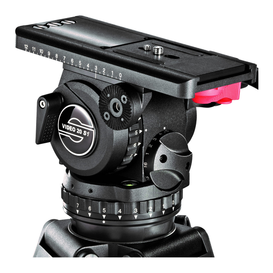
Page 7: Operating Elements
Operating Elements Left View Vertical brake Touch & Go system lock lever Touch & Go system safety lock Counterbalance adjustment knob Vertical drag control Illuminated touch bubble Rosette for left pan bar... - Page 8 Operating Elements Right View Camera plate Spare camera screws Payload range shifter (boost button) Horizontal brake Horizontal drag control Tie down Battery compartment for touch bubble Balance plate clamp lever Rosette for right pan bar...
-
Page 9: Installation
Installation Touch Bubble Mounting the Head The fluid head is fitted with an illuminating touch bubble which The fluid head is designed to be installed onto standard tripods allows easy levelling in poor lighting conditions. The illumination is using the tie down with the 100 mm ball base. The fluid head can be activated by tapping the bubble and will automatically switch off after mounted to a slider or pedestal using a FB converter (# 3913). -
Page 10: Mounting And Dismounting The Camera
Installation Mounting and Dismounting the Camera Loosen the tie down and move the head so that the level bubble is central. Tighten the tie down and check the level bubble remains central when the head is rotated through a full 360º. Apply the horizontal and vertical brakes. - Page 11 Installation With the safety button held down, move the locking lever as far as Attach the camera plate to the camera around its centre of gravity. possible to the left. Additional screws are stored in the platform assembly. The plate or camera will be released.
-
Page 12: Fitting The Pan Bar
Installation Fitting the Pan Bar Mount the camera and plate onto the platform. It will lock automatically and the lock lever will click audibly back into its initial position. Fit and adjust the pan bar to the desired position, tighten the clamping screw ensuring the teeth mesh fully. - Page 13 Installation Adjusting the Pan Bar Configuring the Pan Bar To adjust the position of the pan bar, loosen the clamping screw As standard, the pan bar is configured to mount on the right hand sufficiently to allow the rosettes to rotate without fowling. side of the fluid head.
-
Page 14: Balancing The Payload
Installation Balancing the Payload Adjusting the Centre of Gravity (C of G) Before operating the fluid head, the payload (camera, lens and any Before adjusting the counterbalance, the centre of gravity (C of G) of other fitted accessories) must be correctly balanced to ensure safe the payload must be centred precisely over the axis of the fluid head. - Page 15 Installation Note. The payload range shifter (boost button) is configured to the high setting as standard. Video 18 S2 Estimate the overall weight of the payload. Using the reference 7.7 kg 19.3 kg charts, set the payload range shifter (boost button) to LO or HI 16 lb 42.5 lb...
- Page 16 Installation Hold the pan bar firmly, disengage the vertical brake. Observe how If the payload tilts backwards (points up), slide it towards the the payload moves and where it stops. front of the fluid head (fore). Re-lock the sliding balance plate. If the platform stops in a horizontal position (camera pointing directly forward) or...
-
Page 17: Adjusting The Counterbalance
Installation Additional C of G Adjustments Adjusting the Counterbalance If it is not possible to correctly set the C of G of the payload using the The fluid head is equipped with a 16 step counterbalance adjuster standard method: to accurately balance the payload. Note, moving the counterbalance from one setting to another requires the head to pass the horizontal Move the camera plate to offset the payload further in the required position to take affect. - Page 18 Installation If the payload continues to move upwards when released, the Tilt the payload through positive and negative angles of travel, balance is set too high. Lower the balance adjuster setting by one checking that the payload remains at any angle of tilt unsupported. increment and retest.
-
Page 19: Adjusting The Drags
Installation Adjusting the Drags Turn the horizontal and vertical drag controls to the required index position (1 lowest, 7 highest drag resistance) by aligning the arrow The fluid head is equipped with horizontal and vertical seven step with the dot marker. Turn the brakes off and engage the drag by drag controls. -
Page 20: Transportation
Installation Transportation Transporting with the Pan Bar To ensure smooth and reliable operation over the long life of the fluid To transport the fluid head with the pan bar attached, stow in the head, the following settings should be applied to the controls during vertical position with the tripod legs to prevent damage. -
Page 21: Maintenance
Maintenance Cleaning and Inspection Routine Maintenance Clean the fluid head regularly using a soft cloth. For heavier dirt use a Periodically operate the horizontal and vertical drags through their soft brush and a mild detergent. full range of indexing to ensure the engaging pins in fluid head stay lubricated. -
Page 22: Technical Specification
1.5 kg to 19.3 kg (3.5 lb to 42.5 lb) 1.5 kg to 25 kg (3.5 lb to 55 lb) Boost button, LO range (Video 18 S2) (Video 20 S1) 1.5 kg to 13.1 kg (3.5 lb to 29 lb) 1.5 kg to 15 kg (3.5 lb to 33 lb) -
Page 23: General Notices
General Notices Declaration of Conformity Visit our website for information on how to dispose of this product and its packaging. In countries outside the EU: Dispose of this product at a collection point for the recycling of electrical and electronic equipment according to your local government regulations. -
Page 24: Sicherheit
Sicherheit Wichtige Informationen bezüglich sicherer Montage und sicheren Betriebs dieses Produktes . Bitte lesen Sie diese Informationen WARNUNG! Quetschgefahr für Finger . Langen Sie vor Gebrauch des Produktes . Bitte lesen Sie diese Anleitung mit den Fingern nicht zwischen die Plattform und das zu Ihrer eigenen Sicherheit . -
Page 25: Sicherheit Und Über Diese Bedienungsanleitung
Wartung Bestimmungsgemäße Verwendung WARNUNG! Die Montage nicht zugelassener Teile Die Sachtler Video 18 S2 und Video 20 S1 Fluidköpfe wurden zur und/oder Zubehörteile oder die Durchführung der Wartung durch nicht autorisiertes Personal könnte die Gewährleistung weicher ruckfreier Schwenk- und Neigebewegungen entwickelt. -
Page 26: Lieferumfang
Lieferumfang Beschreibung Artikel-Nr Position Video 18 S2 oder Video 20 S1 1811 oder Fluidkopf 2010 Klemmschale SKO13B0366 Bedienungsanleitung S2022-4980 Kameraplatte 1064 Teleskopierbarer Schwenkarm, rechts 3270... -
Page 27: Bedienelemente
Bedienelemente Ansicht von links Vertikalbremse Verriegelungshebel der Touch & Go Klemmung Sperrknopf der Touch & Go Klemmung Drehknopf zum Einstellen der Kamerabalance Steuerring der Vertikaldämpfung Selbstleuchtende Libelle (Touch Bubble) Rosette für linken Schwenkarm... - Page 28 Bedienelemente Ansicht von rechts Kameraplatte Ersatz-Kameraschrauben Traglastbereich-Stufenregler (Boost-Button) Horizontalbremse Steuerring der Horizontaldämpfung Klemmschale Batteriefach für selbstleuchtende Libelle (Touch Bubble) Verriegelungshebel für Kameraverschiebeplatte Rosette für rechten Schwenkarm...
-
Page 29: Montage
Selbstleuchtende Libelle (Touch Bubble) Montage des Fluidkopfes Dank einer selbstleuchtenden Libelle (Touch Bubble) kann der Der Fluidkopf wurde zur Montage auf Sachtler Stativen mit einer Fluidkopf auch bei schlechten Lichtverhältnissen nivelliert werden. Die Stativschraube mit 100-mm-Kugelschale konzipiert. Der Fluidkopf Beleuchtung wird durch Tippen auf die Libelle aktiviert und schaltet kann mit einem FB-Converter (# 3913) auf einen Slider oder ein sich nach ca. -
Page 30: Einsatz Und Entnahme Der Kamera
Montage Einsatz und Entnahme der Kamera Lösen Sie die Klemmschale und bewegen Sie den Fluidkopf so lange, bis die Luftblase der Libelle mittig ausgerichtet ist. Ziehen Sie die Klemmschale wieder fest und überprüfen Sie, ob die Libelle Schliessen Sie die Horizontal- und zentriert bleibt, wenn der Kopf um vollständige 360º... - Page 31 Montage Schieben Sie mit nach unten gedrücktem Sperrknopf den Befestigen Sie die Kameraplatte ungefähr im Schwerpunkt der Verriegelungshebel bis zum linken Anschlag. Kamera. In der Kamerplattform sind zusätzliche Schrauben vorhanden. Sie können jetzt die Kameraplatte oder Kamera entnehmen.
-
Page 32: Schwenkarmmontage
Montage Schwenkarmmontage Setzen Sie die Kameraplatte auf der Plattform ein. Sie rastet automatisch ein und der Verriegelungshebel schnellt hörbar in seine Ausgangsposition zurück. Bringen Sie den Schwenkarm in die gewünschte Position, ziehen Sie die Klemmschraube fest und stellen Sie dabei sicher, dass die Verzahnungen bündig ineinander greifen. - Page 33 Montage Schwenkarmverstellung Schwenkarmkonfiguration Lösen Sie zum Verstellen des Schwenkarms die Klemmschraube weit Standardmäßig ist der Schwenkarm für die Montage auf der rechten genug, so dass sich die Rosetten ohne Rattern drehen können. Seite des Fluidkopfes konfiguriert. Der Schwenkarm kann wie folgt auch auf der linken Seite montiert werden:...
-
Page 34: Einstellen Der Kamerabalance
Montage Einstellen der Kamerabalance Einstellen des Schwerpunktes (Centre of Gravity, C of G) Vor dem Betrieb des Fluidkopfes muss die Kamerabalance (Kamera, Objektiv und alles weitere Montagezubehör) zur Gewährleistung Vor dem Einstellen des Gewichtsausgleichs muss der Schwerpunkt eines sicheren und zuverlässigen Betriebs korrekt eingestellt werden. (C of G) der Traglast genau über dem Drehpunkt des Fluidkopfes zentriert werden. - Page 35 Montage Hinweis: Der Traglastbereich-Stufenregler (Boost-Button) ist standardmäßig auf eine „hohe“ Einstellung eingestellt. Video 18 S2 Schätzen Sie das Gesamtgewicht der Traglast. Stellen Sie mithilfe 7.7 kg 19.3 kg der Referenzdiagramme den Traglastbereich-Stufenregler (Boost- 16 lb 42.5 lb Button) wie jeweils anwendbar auf LO oder HI . Hinweis: Das Bewegen des Stufenreglers von HI auf LO wird sofort aktiv.
- Page 36 Montage Halten Sie den Schwenkarm fest und lösen Sie die Vertikalbremse. Kippt die Traglast nach hinten (Kamera zeigt nach oben), Beobachten Sie, wie sich die Traglast bewegt und wo sie anhält. schieben Sie die Kamera in Richtung der Vorderseite des Fluidkopfes (nach vorn).
-
Page 37: Einstellen Des Gewichtsausgleichs
Montage Zusätzliche Einstellung des Schwerpunk- Einstellen des Gewichtsausgleichs tes (C of G) Für eine korrekte Kamerabalance verfügt der Fluidkopf über einen 16-stufigen Gewichtsausgleich. Beachten Sie, dass beim Ändern Wenn eine korrekte Einstellung des Schwerpunktes mithilfe der der Stufe des Gewichtsausgleichs der Kopf die horizontale Position Standardverfahren nicht möglich ist: passieren muss, damit dies wirksam wird. - Page 38 Montage Bewegt sich die Traglast nach Freigabe weiter nach oben, ist das Neigen Sie die Traglast durch positive und negative Schwenkwinkel Gleichgewicht zu hoch eingestellt. Verstellen Sie den Drehknopf und überprüfen Sie, dass die Traglast ohne Unterstützung in jedem zum Einstellen des Gewichtsausgleichs um eine weitere Stufe nach unten und prüfen Sie das Verhalten erneut.
-
Page 39: Einstellen Der Dämpfung
Montage Einstellen der Dämpfung Drehen Sie die Steuerringe der Horizontal- und Vertikaldämpfung auf die gewünschte Indexposition (1 ist die niedrigste und Der Fluidkopf verfügt horizontal und vertikal über je sieben Dämp- 7 die höchste Dämpfungsstufe), indem Sie den Pfeil auf die fungsstufen. -
Page 40: Transport
Montage Transport Transport mit montiertem Schwenkarm Um einen reibungslosen und zuverlässigen Betrieb über die lange Für den Transport des Fluidkopfes mit montiertem Schwenkarm Lebensdauer des Fluidkopfes zu gewährleisten, sollten beim kann der Schwenkarm in vertikale Position zu den Stativbeinen hin Transport oder während der Lagerung folgende Einstellungen geschwenkt werden. -
Page 41: Wartung
Wartung Reinigung und Inspektion Routinemäßige Wartung Reinigen Sie den Fluidkopf regelmäßig mit einem weichen Tuch. Bei Betätigen Sie die Steuerringe der Horizontal- und Vertikaldämpfung stärkerer Verschmutzung können Schmutzablagerungen mit einer regelmäßig über den gesamten Indexbereich, um zu gewährleisten, weichen Bürste und mildem Reinigungsmittel entfernt werden. dass die in den Fluidkopf einrastenden Stifte geschmiert bleiben. -
Page 42: Technische Spezifikationen
Technische Spezifikationen Gewicht (Video 18 S2) (Video 20 S1) 4 kg (8,8 lb) 4,1 kg (9 lb) Traglastbereich (Video 18 S2) (Video 20 S1) 1,5 kg bis 19,3 kg (3,5 lb bis 42,5 lb) 1,5 kg bis 25 kg (3,5 lb bis 55 lb) -
Page 43: Allgemeine Hinweise
Allgemeine Hinweise Konformitätserklärung Besuchen Sie unsere Internetseite für Informationen über eine sichere Entsorgung dieses Produkts und dessen Verpackung. In Ländern außerhalb der EU: Entsorgen Sie dieses Produkt in Übereinstimmung mit Ihren lokalen gesetzlichen Bestimmungen an einer Sammelstelle für die Wiederverwertung von Elektrik- und Elektronikgeräten. Entsorgung von Altbatterien Vitec Videocom Limited erklärt, dass dieses Produkt in Übereinstimmung mit der Norm BS EN ISO 9001:2008 hergestellt... - Page 44 Publication No. S2022-4980/1 www.sachtler.com...
Need help?
Do you have a question about the Video 18 S2 and is the answer not in the manual?
Questions and answers