Table of Contents
Advertisement
XJ
CIGAR LIGHTER RELAY . . . . . . . . . . . . . . . . . . . 4
INSTRUMENT CLUSTER . . . . . . . . . . . . . . . . . . . 2
INSTRUMENT PANEL . . . . . . . . . . . . . . . . . . . . . 1
INSTRUMENT PANEL CIGAR LIGHTER . . . . . . . 3
INSTRUMENT PANEL POWER OUTLET . . . . . . . 4
INSTRUMENT PANEL SYSTEM . . . . . . . . . . . . . 1
CIGAR LIGHTER RELAY . . . . . . . . . . . . . . . . . . 12
INSTRUMENT CLUSTER . . . . . . . . . . . . . . . . . . . 5
INSTRUMENT PANEL CIGAR LIGHTER . . . . . . 11
INSTRUMENT PANEL POWER OUTLET . . . . . . 12
CIGAR LIGHTER RELAY . . . . . . . . . . . . . . . . . . 15
CLUSTER BEZEL . . . . . . . . . . . . . . . . . . . . . . . . 16
GLOVE BOX . . . . . . . . . . . . . . . . . . . . . . . . . . . 22
DESCRIPTION AND OPERATION
INSTRUMENT PANEL SYSTEM
DESCRIPTION
The instrument panel serves as the command cen-
ter of the vehicle, which necessarily makes it a very
complex unit. The instrument panel is designed to
house the controls and monitors for standard and
optional powertrains, climate control systems, audio
systems, lighting systems, safety systems and many
other comfort or convenience items. The instrument
panel is also designed so that all of the various con-
trols can be safely reached and the monitors can be
easily viewed by the vehicle operator when driving,
while still allowing relative ease of access to each of
these items for service. See the owner's manual in
the vehicle glove box for more information on the fea-
tures, use and operation of all of the instrument
panel components and systems.
This group is responsible for covering service infor-
mation for the vehicle instrument panel systems.
However, complete service information coverage for
all of the systems and components housed in the
instrument panel in a single section of the service
manual would not be practical. Therefore, the service
information for any component will be found in the
group designated to cover the vehicle system that the
component belongs to, even though the component is
INSTRUMENT PANEL SYSTEMS
CONTENTS
page
INSTRUMENT PANEL SYSTEMS
GLOVE BOX COMPONENTS . . . . . . . . . . . . . . . 22
GLOVE BOX LATCH STRIKER . . . . . . . . . . . . . 24
HEADLAMP SWITCH . . . . . . . . . . . . . . . . . . . . 17
INSTRUMENT CLUSTER . . . . . . . . . . . . . . . . . . 18
INSTRUMENT CLUSTER COMPONENTS . . . . . 18
INSTRUMENT PANEL ACCESSORY SWITCH
BEZEL . . . . . . . . . . . . . . . . . . . . . . . . . . . . . . 15
INSTRUMENT PANEL ASSEMBLY . . . . . . . . . . 26
INSTRUMENT PANEL CENTER BEZEL . . . . . . . 14
BRACKET . . . . . . . . . . . . . . . . . . . . . . . . . . . . 25
INSTRUMENT PANEL END CAP . . . . . . . . . . . . 24
INSTRUMENT PANEL TOP COVER . . . . . . . . . . 21
KNEE BLOCKER . . . . . . . . . . . . . . . . . . . . . . . . 13
STEERING COLUMN OPENING COVER . . . . . . 13
mounted on or in the instrument panel. If you cannot
locate a listing for the component or system you are
servicing in the table of contents for this group, or if
you are uncertain as to which vehicle system a com-
ponent belongs to, it is suggested that you refer to
the alphabetical Component and System Index
found at the back of this service manual.
NOTE: This group covers both Left-Hand Drive
(LHD) and Right-Hand Drive (RHD) versions of this
model. Whenever required and feasible, the RHD
versions of affected vehicle components have been
constructed as mirror-image of the LHD versions.
While most of the illustrations used in this group
represent only the LHD version, the diagnostic and
service procedures outlined can generally be
applied to either version. Exceptions to this rule
have been clearly identified as LHD or RHD, if a
special illustration or procedure is required.
INSTRUMENT PANEL
DESCRIPTION
This instrument panel uses a full-width structural
plastic foundation as its primary support. When the
two primary molded plastic components of this struc-
ture are vibration welded together they provide supe-
rior instrument panel stiffness and integrity to help
8E - 1
page
Advertisement
Table of Contents

Related Manuals for Jeep XJ


Summary of Contents for Jeep XJ
-
Page 1: Table Of Contents
INSTRUMENT PANEL SYSTEMS 8E - 1 INSTRUMENT PANEL SYSTEMS CONTENTS page page DESCRIPTION AND OPERATION GLOVE BOX COMPONENTS ....22 CIGAR LIGHTER RELAY ....4 GLOVE BOX LATCH STRIKER . -
Page 2: Description And Operation
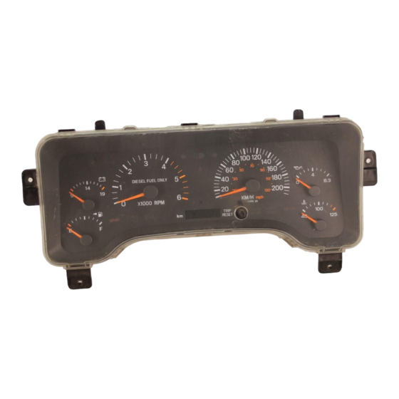
8E - 2 INSTRUMENT PANEL SYSTEMS DESCRIPTION AND OPERATION (Continued) reduce buzzes, squeaks, and rattles even on the The low-line cluster includes the following analog bumpiest roads. gauges: • Fuel gauge This type of construction also provides improved • Speedometer. energy absorption which, in conjunction with the dual airbag modules and seat belts, helps to improve This cluster also includes provisions for the follow-... - Page 3 INSTRUMENT PANEL SYSTEMS 8E - 3 DESCRIPTION AND OPERATION (Continued) Electrically Heated Systems for more information on The seat belt reminder lamp is controlled by the the timer function of the instrument cluster. instrument cluster programming. The instrument The instrument clusters for this model are serviced cluster circuitry uses CCD data bus messages from only as complete units.
-
Page 4: Instrument Panel
8E - 4 INSTRUMENT PANEL SYSTEMS DESCRIPTION AND OPERATION (Continued) OPERATION current capacities, terminal patterns, and terminal functions. The cigar lighter consists of two major components: The cigar lighter relay cannot be repaired or a knob and heating element unit, and the cigar adjusted and, if faulty or damaged, it must be lighter base or receptacle shell. -
Page 5: Diagnosis And Testing
INSTRUMENT PANEL SYSTEMS 8E - 5 switch output (run/start) circuit to the ignition switch DIAGNOSIS AND TESTING as required. (7) Turn the ignition switch to the Off position. INSTRUMENT CLUSTER Disconnect and isolate the battery negative cable. If all of the gauges and/or indicator lamps are inop- Install the instrument cluster. - Page 6 8E - 6 INSTRUMENT PANEL SYSTEMS DIAGNOSIS AND TESTING (Continued) lizer Module (SKIM) or the inputs to one of these ANTI-LOCK BRAKE SYSTEM LAMP electronic control modules. Use a DRB scan tool and The diagnosis found here addresses an inoperative the proper Diagnostic Procedures manual for testing Anti-lock Brake System (ABS) lamp condition.
- Page 7 INSTRUMENT PANEL SYSTEMS 8E - 7 DIAGNOSIS AND TESTING (Continued) Fig. 1 Low-Line Instrument Cluster Actuator Test...
- Page 8 8E - 8 INSTRUMENT PANEL SYSTEMS DIAGNOSIS AND TESTING (Continued) Fig. 2 High-Line Instrument Cluster Actuator Test...
- Page 9 INSTRUMENT PANEL SYSTEMS 8E - 9 DIAGNOSIS AND TESTING (Continued) while driving, refer Base Brake System for vehicles between the red brake warning indicator driver cir- not equipped with the four wheel anti-lock brake sys- cuit cavity of the instrument cluster wire harness tem, or refer to Antilock Brakes for vehicles connector A and a good ground.
- Page 10 8E - 10 INSTRUMENT PANEL SYSTEMS DIAGNOSIS AND TESTING (Continued) Remove the instrument cluster. With the transfer (5) Turn the ignition switch to the Off position. case switch wire harness connector still disconnected, Disconnect and isolate the battery negative cable. check for continuity between the full time four wheel Remove the instrument cluster.
-
Page 11: Instrument Panel Cigar Lighter
INSTRUMENT PANEL SYSTEMS 8E - 11 DIAGNOSIS AND TESTING (Continued) ment Cluster in the Contents of Group 8W - Wiring (1) Disconnect and isolate the battery negative Diagrams. cable. Remove the instrument cluster. (1) Check the fused ignition switch output (run/ (2) Connect the battery negative cable. -
Page 12: Instrument Panel Power Outlet
8E - 12 INSTRUMENT PANEL SYSTEMS DIAGNOSIS AND TESTING (Continued) CIGAR LIGHTER RELAY at the fused B(+) circuit cavity of the accessory relay wire harness connector. If OK, go to Step 2. If not The cigar lighter relay (Fig. 3) is located in the OK, repair the fused B(+) circuit to the fuse in the junction block, on the right cowl side inner panel junction block as required. -
Page 13: Removal And Installation
INSTRUMENT PANEL SYSTEMS 8E - 13 DIAGNOSIS AND TESTING (Continued) (3) Remove the plastic protective cap from the power outlet receptacle. Check for continuity between the inside circumference of the power outlet recepta- cle and a good ground. There should be continuity. If OK, go to Step 4. - Page 14 8E - 14 INSTRUMENT PANEL SYSTEMS REMOVAL AND INSTALLATION (Continued) INSTRUMENT PANEL CENTER BEZEL WARNING: ON VEHICLES EQUIPPED WITH AIR- BAGS, REFER GROUP PASSIVE RESTRAINT SYSTEMS BEFORE ATTEMPTING ANY STEERING WHEEL, STEERING COLUMN, INSTRUMENT PANEL COMPONENT DIAGNOSIS OR SERVICE. FAILURE TO TAKE THE PROPER PRE- CAUTIONS COULD RESULT IN ACCIDENTAL AIR- BAG DEPLOYMENT AND POSSIBLE PERSONAL INJURY.
-
Page 15: Cigar Lighter Relay
INSTRUMENT PANEL SYSTEMS 8E - 15 REMOVAL AND INSTALLATION (Continued) INSTRUMENT PANEL ACCESSORY SWITCH switches, the cigar lighter and the accessory power outlet on the back of the accessory switch bezel. BEZEL (3) Position the accessory switch bezel onto the instrument panel. -
Page 16: Cluster Bezel
8E - 16 INSTRUMENT PANEL SYSTEMS REMOVAL AND INSTALLATION (Continued) REMOVAL (1) Disconnect and isolate the battery negative cable. (2) Remove the knee blocker from the instrument panel. Refer to Knee Blocker in the Removal and Installation section of this group for the procedures. (3) Remove the center bezel from the instrument panel. - Page 17 INSTRUMENT PANEL SYSTEMS 8E - 17 REMOVAL AND INSTALLATION (Continued) (3) Press firmly on the cluster bezel over each of and shaft release button on the inboard side of the the snap clip locations until each of the snap clips is switch body.
-
Page 18: Instrument Cluster
8E - 18 INSTRUMENT PANEL SYSTEMS REMOVAL AND INSTALLATION (Continued) INSTRUMENT CLUSTER the cluster connector receptacles when the cluster is installed in the instrument panel. (3) Install and tighten the four screws that secure WARNING: ON VEHICLES EQUIPPED WITH AIR- the instrument cluster to the instrument panel. - Page 19 INSTRUMENT PANEL SYSTEMS 8E - 19 REMOVAL AND INSTALLATION (Continued) (3) Turn the bulb holder counterclockwise about (4) Gently pull the cluster lens away from the clus- sixty degrees on the cluster electronic circuit board. ter housing. (4) Pull the bulb and bulb holder unit straight ODOMETER RESET KNOB BOOT back to remove it from the bulb mounting hole in the (1) Disconnect and isolate the battery negative...
- Page 20 8E - 20 INSTRUMENT PANEL SYSTEMS REMOVAL AND INSTALLATION (Continued) (4) Work around the perimeter of the cluster hous- CAUTION: Always use the correct bulb size and ing to disengage each of the latches that secure the type for replacement. An incorrect bulb size or type cluster hood and mask unit to the cluster housing may overheat and cause damage to the instrument (Fig.
- Page 21 INSTRUMENT PANEL SYSTEMS 8E - 21 REMOVAL AND INSTALLATION (Continued) (4) Install the cluster lens onto the cluster hous- REMOVAL ing. Refer to Instrument Cluster Components - (1) Disconnect and isolate the battery negative Cluster Lens in the Removal and Installation sec- cable.
-
Page 22: Glove Box Components
8E - 22 INSTRUMENT PANEL SYSTEMS REMOVAL AND INSTALLATION (Continued) (6) Install the cluster bezel onto the instrument REMOVAL panel. Refer to Cluster Bezel in the Removal and (1) Disconnect and isolate the battery negative Installation section of this group for the procedures. cable. - Page 23 INSTRUMENT PANEL SYSTEMS 8E - 23 REMOVAL AND INSTALLATION (Continued) REMOVAL GLOVE BOX HINGE, BIN, INNER DOOR AND LATCH (1) Disconnect and isolate the battery negative cable. (2) Remove the glove box from the instrument panel. Refer to Glove Box - Removal in the Removal and Installation section of this group for the procedures.
-
Page 24: Glove Box Latch Striker
8E - 24 INSTRUMENT PANEL SYSTEMS REMOVAL AND INSTALLATION (Continued) GLOVE BOX LATCH STRIKER INSTRUMENT PANEL END CAP WARNING: ON VEHICLES EQUIPPED WITH AIR- WARNING: ON VEHICLES EQUIPPED WITH AIR- BAGS, REFER GROUP PASSIVE BAGS, REFER GROUP PASSIVE RESTRAINT SYSTEMS BEFORE ATTEMPTING ANY RESTRAINT SYSTEMS BEFORE ATTEMPTING ANY STEERING WHEEL,... -
Page 25: Instrument Panel Center Support
INSTRUMENT PANEL SYSTEMS 8E - 25 REMOVAL AND INSTALLATION (Continued) Removal and Installation section of this group for the INSTRUMENT PANEL CENTER SUPPORT procedures. BRACKET (4) Remove the passenger side airbag module from the instrument panel. Refer to Passenger Side Air- WARNING: ON VEHICLES EQUIPPED WITH AIR- bag Module in the Removal and Installation section BAGS,... - Page 26 8E - 26 INSTRUMENT PANEL SYSTEMS REMOVAL AND INSTALLATION (Continued) INSTALLATION ter Support Bracket in the Removal and Installa- tion section of this group for the procedures. (1) Position the center support bracket to the (6) Remove the steering column from the vehicle. instrument panel.
- Page 27 INSTRUMENT PANEL SYSTEMS 8E - 27 REMOVAL AND INSTALLATION (Continued) Fig. 23 Instrument Panel Assembly Remove/Install (2) Install and tighten the four screws and two (8) Reconnect the two wire harness connectors nuts that secure the top of the instrument panel to located near the instrument panel-to-floor wire har- the top of the dash panel near the base of the wind- ness connector at the floor panel transmission tunnel...
- Page 28 8E - 28 INSTRUMENT PANEL SYSTEMS REMOVAL AND INSTALLATION (Continued) (14) Install the knee blocker onto the instrument Trim in the Removal and Installation section of panel. Refer to Knee Blocker in the Removal and Group 23 - Body for the procedures. Installation section of this group for the procedures.
Need help?
Do you have a question about the XJ and is the answer not in the manual?
Questions and answers