Table of Contents
Advertisement
Available languages
Available languages
Quick Links
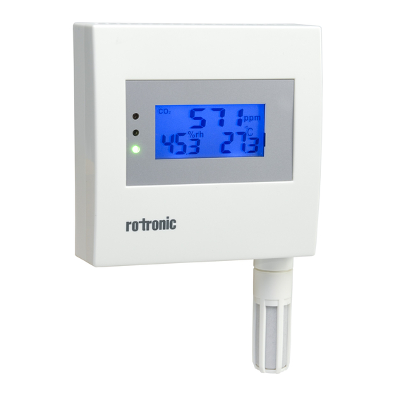
CF1 S
erieS
ShORT InSTRuCTIOn Manual
Digital measurement transducer for humidity, temperature, and CO
Congratulations on the purchase of your new CF1 series measurement transducer!
Please read these short instructions through carefully before installing the unit.
General Description
The units in the CF1 series are universal measurement transducers for transmission of humidity,
temperature and CO
. You will find more information at www.rotronic.com
2
Dimensions / Connections
Typ S
32
86
Typ R
86
32
Typ D
98
117
117
90
77
199
77
32
199
Mechanical Installation
A
Note:
In order to receive correct measurements, you must ensure that the measurement
transducer is subjected to the flow of the air to be measured.
1. Remove the mounting plate by loosening the screw.
2. Attach the mounting plate at the desired position with 2 screws.
.
a) Choose a representative position for installation:
2
Install the measuring head in a place at which the conditions of airspeed, humidity,
temperature and pressure are typical of the environment to be measured
b) Ensure that the ambient pressure at the point of measurement is kept as constant
as possible
c) Avoid installation close to heating elements, refrigeration units, or cold or warm walls
d) Do not install the measurement transducer in potentially explosive environments
e) Install the measurement transducer indoors
f) Avoid any physical contact with the sensor
g) Avoid installation in dusty environments
h) Avoid physical shocks or vibrations
Recommended Tools for Installation
• Phillips screwdriver
• Standard screwdriver
• Open-end wrench, 27 mm
65
Positioning in offices (Typ S/R)
Recomended mounting hight about ca.1.20m (respiration level)
Mounting the duct version
with flange
62.5
flange
Probe
Probe
62.5
housing
62.5
Mounting position
Information for accurate measurment result: Max. air flow shouldn't 20m/s exceed
Channel
Electrical Installation
A
Caution:
Wrong supply voltages and excessive loads on the outputs can damage
the transmitter.
32
Terminal Configuration / Wiring Diagrams
Using the table "Supply Voltage / Technology", identify the type, so that you can use the following
connection schematics:
Power Supply
Type
Supply voltage
Load
Max.500 Ω
HF132
12..28 VAC / 15..40V DC
HF135
12..28 VAC / 15..40V DC
Max.10 kΩ
Find Quality Products Online at:
3-core
Type S/R
Type D
Current output
V +
without flange
V −
(GND)
Voltage output
V+
housing
V −
(GND)
Schematic
Description
+
V
Power supply+
V -
Power supply -
Temp +
Temperature analog output +
Temp -
Temperature analog output -
RH +
Humidity analog output +
RH -
Humidity analog output -
CO
+
Carbon dioxide analog output +
2
CO
-
Carbon dioxide analog output -
2
Relay
Normally open (NO)
Programming
The initial settings of the units are made in the factory to your order. The transmitters are adjusted
in the factory, so checking and readjustment at installation time are not necessary. The units
can be put into operation immediately after installation. Using the SW21 or HW4 software and a
standard mini-USB cable, you can make the following settings:
• Scaling of the analogue outputs (°C & %RH)
• 1-point adjustment for humidity
• 1-point adjustment for CO
2
• General settings
• Selectable analog signal ( Not selectable from V to mA output)
• Change CO
(2000/5000ppm)
2
• Set CO
threshold
2
• Relay source (CO
,°C,%RH)
2
• ABC for CO
(On/Off)
2
• Backlight (On/Off)
Output
Procedure
4..20 mA
• Connect the power supply
0..10 V
• Connect the measurement transducer to the PC via mini-USB cable
• Programm the measurement transducer using the SW21 or HW4 software
• Remove the power supply (The measurement transducer must be isolated
from the power for at least 2 seconds)
GlobalTestSupply
www.
.com
Sources of Error
Measured values can be compromised by the following influences:
Temperature Errors
Through insufficient adaptation time, cold outer walls, heaters, direct sunlight, etc.
humidity Errors
Through vapor, splashed water, dripping water or condensation on the sensor, etc. This does not,
however, impair reproducibility or long-term stability, even when the sensor is exposed to high
Relay
Service
humidity or saturation with water vapor (condensation) for a prolonged period.
interface
Carbon Dioxide Errors
Plants that are placed close to the measurement transducer neutralize the CO
that radiate carbon dioxide can also indicate an increased CO
the surroundings that are to be measured.
Contamination
Through dust in the air. The choice of sensor filter depends on the degree of contamination at the
measurement point, and the filter should be cleaned or replaced at intervals.
Service
interface
Periodical calibration of the sensor / transmitter
Both the temperature sensor and the associated electronics are very stable, and do not normally
have to be changed or calibrated after calibration in the factory. The long-term stability of the
ROTRONIC Hygromer humidity sensor is typically better than 1 %RH per year. For maximum precision,
we recommend calibration of the sensors approximately every six to twelve months. In the case of ap-
CO
+
2
plications in which the sensor is subjected to pollutants, more frequent calibration may be necessary.
RH +
Calibration can be carried out by the user onsite, or in the laboratory or workshop. The electronics do
T +
not normally need to be calibrated, and cannot be repaired in the field. In case of problems, get in
touch with Rotronic AG Service.
Technical Data (Operation)
T −
RH − CO
−
2
Temperature
Humidity
CO
2
Precision %RH (10...90 %RH)
CO
+
2
Precision °C at 23 °C ± 5 K
RH+
T +
Precision CO
Scaling the analog output signals
T −
RH −
CO
−
2
Humidity
Temperature
CO
2
Outputs
Relay
ROTRONIC AG, CH-8303 Bassersdorf
Tel. +41 44 838 11 44, www.rotronic.com
ROTRONIC Messgeräte GmbH, D-76275 Ettlingen
Tel. +49 7243 383 250, www.rotronic.de
ROTRONIC SARL, 56, F - 77183 Croissy Beaubourg
Tél. +33 1 60 95 07 10, www.rotronic.fr
ROTRONIC Italia srl, I- 20157 Milano
Tel. +39 2 39 00 71 90, www.rotronic.it
ROTRONIC Instruments (UK) Ltd, West Sussex RH10 9EE
Phone +44 1293 571000, www.rotronic.co.uk
ROTRONIC Instrument Corp, NY 11788, USA
Phone +1 631 427-3898, www.rotronic-usa.com
ROTRONIC Canada Inc.,Canada L8W 3P7
Phone + 1 905 754 5164, www.rotronic.ca
ROTRONIC Instruments Pte. Ltd., Singapore 159836
Phone +65 6376 2107, www.rotronic.sg
ROTRONIC Shanghai Rep. Office, Shanghai 200233, China
Phone +86 40 08162018, www.rotronic.cn
sales@GlobalTestSupply.com
. Objects or persons
2
content that is not strictly part of
2
0...50 °C
0...100 %RH, non-condensing
0...2000 ppm or 0...5000 ppm
< 3 %RH
± 0.3 K
± 1 K Type S with display
(0...2000 ppm)
± 40 ppm ± 3 % of the measured value
2
(0...5000 ppm)
± 10 % of the measured value
0..100 %RH
-100...250 °C
0...2000 ppm or 0...5000 ppm
Current or voltage signal
Each parameter can be set via software
Advertisement
Table of Contents

Related Manuals for Rotronic CF1 Series


Summary of Contents for Rotronic CF1 Series
- Page 1 Do not install the measurement transducer in potentially explosive environments The units in the CF1 series are universal measurement transducers for transmission of humidity, the surroundings that are to be measured. e) Install the measurement transducer indoors temperature and CO .
- Page 2 Werkskalibrierung normalerweise nicht verändert oder kalibriert werden. Die Langzeitstabilität der Empfohlene Montagehöhe ca. 1.20m (Atmung Ebene) ROTRONIC Hygromer Feuchtefühler ist typischerweise besser als 1 %rF pro Jahr. Für eine maximale Genau- igkeit empfehlen wir eine Kalibrierung der Fühler ca. alle sechs bis zwölf Monate. In Anwendungen wo der RH + Sensor Schadstoffen ausgesetzt ist, kann eine häufigere Kalibrierung notwendig sein.
- Page 3 L’électronique ne nécessite normalement pas d’étalonnage et ne peut pas V − T − RH − CO − être réparée sur site. En cas de problème, adressez-vous au secteur de service de la société Rotronic SA. Bride (GND) Caractéristiques techniques (opération) Capteurs...
- Page 4 La stabilità a lungo termine • Chiave a forcella 27 mm della sonda per umidità Hygromer ROTRONIC risulta di solito migliore rispetto ad un valore dell’1 %UR/ Uscita in corrente anno.
Need help?
Do you have a question about the CF1 Series and is the answer not in the manual?
Questions and answers