Table of Contents
Advertisement
Advertisement
Table of Contents

Related Manuals for Woodward RP-3000


Summary of Contents for Woodward RP-3000
- Page 1 RP-3000 Manual Remote Panel RP-3000 Software Version 1.xxxx or higher 37534C...
- Page 2 Designed in Germany Woodward GmbH Handwerkstrasse 29 70565 Stuttgart Germany Telephone: +49 (0) 711 789 54-510 Fax: +49 (0) 711 789 54-101 email: stgt-info@woodward.com Internet: http://www.woodward.com © 2013 RP-3000 | Remote Panel 37534C...
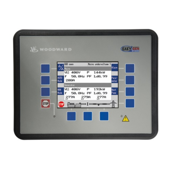
- Page 3 Protective earth PE Relay output terminal RS-232 interface connector The RP-3000 is a remote control and annunciation panel for use with the back-panel mounted easYgen-3100/3400 or door-mounted easYgen-3200/3500 genset controls. It has the same look and feel of the easYgen-3200/3500 genset control, enabling user-friendly transition between genset control sources.
- Page 4 Only one easYgen can be connected at once. A typical application for the remote panel is to control back-panel mounted easYgen-3100/3400 devices. In this case, the RP-3000 provides control from the front panel with considerably reduced wiring effort. The high-voltage connections are located safely on the back panel.
- Page 5 Therefore it can be necessary to install an external emergency stop button. The remote panel RP-3000 is connected via a serial interface to the genset control. Please keep in mind that the involved refreshing times of the displayed data are slower on the RP-3000 compared to the easYgen-3200/3500.
- Page 6 Display of free configu‐ Every time you switch on the supply voltage of the rable text RP-3000 all free configurable texts are initially shown as default text. In the background starts an automatic import process – replacing the default text by the free configurable text (loaded from the connected easYgen).
-
Page 7: Table Of Contents
Serial Interface.......................... 34 3.2.5.1 RS-232 Interface........................34 CAN Bus Interface........................35 Configuration........................... 39 Basic Setup..........................39 4.1.1 Configure Language........................39 4.1.2 Configure Display........................39 4.1.3 Lamp Test..........................39 4.1.4 Enter Password......................... 40 4.1.5 Password System........................42 37534C RP-3000 | Remote Panel... - Page 8 4.2.2.1 Setup Parameters RP-3000...................... 49 4.2.2.2 Setup Parameters easYgen-3000 Series.................. 51 Operation..........................57 Basic Navigation........................57 Specialised RP-3000 Menu Screens..................57 Relay Output..........................59 Application..........................61 Overview........................... 61 Connection CAN Interface 2...................... 62 Connection CAN Interface 1...................... 62 Interfaces And Protocols......................65 Interfaces Overview........................
- Page 9 Table of contents Index............................75 37534C RP-3000 | Remote Panel...
- Page 10 Table of contents RP-3000 | Remote Panel 37534C...
-
Page 11: General Information
WARNING! This combination of symbol and signal word indicates a possibly-dangerous situation that could cause death or severe injuries if it is not avoided. 37534C RP-3000 | Remote Panel... -
Page 12: Copyright And Disclaimer
Woodward GmbH assumes no liability for damages due to: Failure to comply with the instructions in this operating manual... -
Page 13: Service And Warranty
- including excerpts - as well as exploitation and/or communi‐ cation of the content, are not permitted without a written declara‐ tion of release by Woodward GmbH. Actions to the contrary exact damage compensation. We reserve the right to enforce additional claims. -
Page 14: Personnel
Persons with impaired reactions due to, for example, the consumption of drugs, alcohol, or medication are prohibited. When selecting personnel, the age-related and occupation-related regulations governing the usage location must be observed. RP-3000 | Remote Panel 37534C... -
Page 15: General Safety Notes
37534C RP-3000 | Remote Panel... - Page 16 Alternatively wear an ESD wrist band connected to ground. Keep plastic, vinyl, and Styrofoam materials (such as plastic or Styrofoam cups, cigarette packages, cellophane wrappers, vinyl books or folders, plastic bottles, etc.) away from the control unit, modules and work area. RP-3000 | Remote Panel 37534C...
- Page 17 Protection of Electronic Controls, Printed Circuit Boards, and Modules". Notes on marine usage Marine usage of the RP-3000 connected to the easYgen genset control requires additional precautions as listed below: The specified marine approvals are initially only valid for metal housing units. They are only valid for plastic housing units, if they are installed using the screw kit .
-
Page 18: Protective Equipment And Tools
Please refer to the corresponding documents – issued by marine Classification Societies for the applicable reqiurements. The RP-3000 is type approved by LR Lloyd's Register. – Please consider for final functional arrangements to comply with appropriate Lloyd's Register Rules as subject of the Plan Approval process. -
Page 19: System Overview
Display And Status Indicators RP-3000 display The display (Fig. 4) as part of the RP-3000 is used for direct access to status information and configuration. For information on the usage of the graphical user interface refer to Ä... -
Page 20: Device Update
2.3.1 Software Version General notes The device software of the RP-3000 remote panel and the easYgen-3000 Series genset control are closely linked together. This means that the software of both devices always needs to fit together to make the entire system work correctly. - Page 21 The provided product CD contains in the section two different ways to find the suitable software version for your RP-3000 remote panel. That means the RP-3000 software version is always chosen from the viewpoint of the easYgen-3000 Series genset control.
-
Page 22: Update
The following prerequisites are required to update the software ver‐ sion of your RP-3000. PC running ToolKit configuration software Serial port (RS-232) of the RP-3000 is connected to a serial COM port of the PC Software update file (*.scp), provided on product CD For detailed information about the ToolKit configuration software please refer to the chapter "Operation"... - Page 23 Select ceed. Fig. 10: Load application - *.scp file “Next” to proceed. Select Please do not select to restore the current device settings after the software update. Fig. 11: Load application - restore set‐ tings 37534C RP-3000 | Remote Panel...
-
Page 24: Troubleshooting
"Expected RP-3000" software number. Ä Chapter 2.3.1 If Fig. 15 is shown please follow the instructions in “Software Version” on page 20 to update the RP-3000 with the cor‐ rect software version. Fig. 16 shows the easYgen-3000 version page. The software ver‐... - Page 25 System Overview Device Update > Troubleshooting To use the automatic easYgen-3000 Series - RP-3000 version recognition after changing the easYgen-3000 software version, it is always necessary to restart the RP-3000 as described above. Fig. 16: Version screen (easYgen-3000) Software combinations The automatic software version recognition works only under cer‐...
- Page 26 System Overview Device Update > Troubleshooting RP-3000 | Remote Panel 37534C...
-
Page 27: Installation
217 mm Panel cutout 183 mm + 1.0 mm Housing 181 mm dimension Width Total 282 mm Panel cutout 249 mm + 1.1 mm Fig. 18: Cutout schematic Housing 247 mm dimension Depth Total 67 mm 37534C RP-3000 | Remote Panel... -
Page 28: Clamp Fastener Installation
Insert the unit into the panel cutout. Verify that the unit fits correctly in the cutout. If the panel cutout is not big enough, enlarge it accordingly. Fig. 20: Insert screws in clamps RP-3000 | Remote Panel 37534C... -
Page 29: Screw Kit Installation
Fig. 23: Reattach terminals 3.1.2 Screw Kit Installation The housing is equipped with 12 nut inserts (Fig. 24), which must all be tightened properly to achieve the required degree of protection. 37534C RP-3000 | Remote Panel... - Page 30 Tighten the screws with a crosswise pattern to ensure even pressure distribution. If the thickness of the panel sheet exceeds 2.5 mm, be sure to use screws with a length exceeding the panel sheet thickness by 4 mm. RP-3000 | Remote Panel 37534C...
-
Page 31: Setup Connections
1000MCM 0.25 350MCM 0.34 500MCM Table 3: Conversion chart - wire sizes 3.2.1 Terminal Allocation General notes The device terminals are allocated as follows: Plastic housing - shown in Fig. 25 Fig. 25: Plastic housing 37534C RP-3000 | Remote Panel... -
Page 32: Wiring Diagram
Installation Setup Connections > Wiring Diagram 3.2.2 Wiring Diagram Fig. 26: Wiring diagram RP-3000 | Remote Panel 37534C... -
Page 33: Power Supply
The conductor providing the connection must have a wire larger than or equal to 2.5 mm² (14 AWG). The connection must be performed properly. Woodward recommends to use one of the following slow-acting protective devices in the supply line to ter‐ minal 63: Fuse NEOZED D01 6A or equivalent or –... -
Page 34: Relay Output
Fixed to "Ready for operation" 2.5 mm² Notes N.O.: normally open (make) contact – 3.2.5 Serial Interface 3.2.5.1 RS-232 Interface Pin assignment Terminal Description Not connected RxD (receive data) TxD (transmit data) Fig. 30: SUB-D connector - pins RP-3000 | Remote Panel 37534C... -
Page 35: Can Bus Interface
Please note that the CAN bus must be terminated with a resistor, which corresponds to the impedance of the cable (e.g. 120 Ohms, 1/4 W) at both ends. The termination resistor is connected between CAN-H and CAN-L (Fig. 33). 37534C RP-3000 | Remote Panel... - Page 36 All bus connections of the easYgen are internally grounded via an RC element. Therefore, they may either be grounded directly (rec‐ ommended) or also via an RC element on the opposite bus con‐ nection. Fig. 33: Bus shielding RP-3000 | Remote Panel 37534C...
- Page 37 – length The CAN bus cable is routed in close proximity – with power cables Woodward recommends the use of shielded, twisted- pair cables for the CAN bus (see examples). Lappkabel Unitronic LIYCY (TP) 2×2×0.25 – UNITRONIC-Bus LD 2×2×0.22 –...
- Page 38 Installation CAN Bus Interface RP-3000 | Remote Panel 37534C...
-
Page 39: Configuration
This parameter identification number is also displayed in the ToolKit configuration screens next to the respec‐ tive parameter. The following chapter (Ä Chapter 4.1 “Basic Setup” on page 39) describes only parameters which directly configure the RP-3000 remote panel. Basic Setup 4.1.1 Configure Language General notes The following parameter is used to set the unit language. -
Page 40: Enter Password
CL1, CL2 and Standard password = "0 CL3. 0 0 3" Access granted by this password expires two hours after the password has been entered and the user is returned to the CL0 level. RP-3000 | Remote Panel 37534C... - Page 41 Unlocked (Code Level 1) Parameter Setting range Description [Default] 10404 Password for 0000 to 9999 To configure the easYgen-3000 genset control via RP-3000 remote panel, the remote config. password for remote configuration must be entered here. [random number] 10409 Code level (display only) This value displays the remote code level, which is currently enabled for remote config.
-
Page 42: Password System
Configuration Configure CAN Interface > Connection CAN Interface 2... > Setup Parameters RP-3000 4.1.5 Password System General notes The following passwords grant varying levels of access to the parameters. Each individual password can be used to access the appropriate configuration level through multiple access... - Page 43 Configuration Configure CAN Interface > Connection CAN Interface 2... > Setup Parameters RP-3000 Insert the password display “Parameter è System Management Select System Management RP-3000” . è Set the "Password Display" to code level "3" or higher. Factory default settings...
- Page 44 Configuration Configure CAN Interface > Connection CAN Interface 2... > Setup Parameters RP-3000 Basic code level xxxx Commissioning code level xxxx Temp. commissioning code level xxxx Table 9: Reset factory default values screen CAN communication parameters Use the same parameter screen like before.
-
Page 45: Setup Parameters Easygen-3000 Series
"Node-ID 7" (Refer to Ä “CANopen interface screen 1/3” Table on page 45 for details). Please make sure that the parameter "RP-3000" is config‐ Ä “CANopen interface screen ured to "Node-ID 6" (Refer to 2/3” Table on page 46 for details). - Page 46 Phoenix 12 AI 4AO Phoenix 16 AI 4AO Phoenix 16 AI 4AO DI/DO 1..32 RP-3000 Node-ID 6 Configure external devices Table 15: CANopen interface screen 3/3 Please make sure that a physical CAN connection is established. RP-3000 | Remote Panel 37534C...
- Page 47 Now the CAN communication should run. Please check the following: Relay [R 01] is closed. – The main screen of the RP-3000 should not show – the error message “CAN Fault !!”. If you navigate to “Main screen è Parameter” the –...
- Page 48 Now the CAN communication should run. Please check the following: – Relay [R 01] is closed. The main screen of the RP-3000 should not show – the error message “CAN Fault !!”. If you navigate to “Main screen è Parameter” the –...
-
Page 49: Connection Can Interface 1 (Easygen-3000)
Configuration Configure CAN Interface > Connection CAN Interface 1... > Setup Parameters RP-3000 4.2.2 Connection CAN Interface 1 (easYgen-3000) 4.2.2.1 Setup Parameters RP-3000 The RP-3000 can only be configured using the front panel. Insert the password display “Parameter è System Management Select System Management RP-3000”... - Page 50 Configuration Configure CAN Interface > Connection CAN Interface 1... > Setup Parameters RP-3000 Configure CAN interface 1 -> Configure display backlight Key activat. Time until backlight shutdown 120 min Factory default settings Reset factory default values Password Display xxxx Code level display...
-
Page 51: Setup Parameters Easygen-3000 Series
COB-ID SYNC Message 00000080 hex Producer SYNC Message time 00020 ms COB-ID TIME Message C0000100 hex Additional Server SDOs -> Receive PDO 1 -> Receive PDO 2 -> Table 21: Configure CAN interface 1 screen 37534C RP-3000 | Remote Panel... - Page 52 Receive PDO 2 -> Receive PDO 3 -> Receive PDO 4 -> Receive PDO 5 -> Transmit PDO 1 -> Transmit PDO 2 -> Transmit PDO 3 -> Table 23: Configure CAN interface 1 screen RP-3000 | Remote Panel 37534C...
- Page 53 Transmit PDO 1 -> Transmit PDO 2 -> Transmit PDO 3 -> Table 25: Configure CAN interface 1 screen COB-ID 000002C6 hex Transmission type Event timer 00020 ms Selected Data Protocol 05009 Number of Mapped Objects 37534C RP-3000 | Remote Panel...
- Page 54 Now the CAN communication should run. Please check the following: Relay [R 01] is closed. – The main screen of the RP-3000 should not show – the error message “CAN Fault !!”. If you navigate to “Main screen è Parameter” the –...
- Page 55 Use the same parameter screen like before (Refer to Fig. 37 for details). Set the "COB-ID" (transmit PDO 3) to "710" (decimal). Please make sure that the parameter "Selected Data Pro‐ tocol" (transmit PDO 3) is configured to "5009". 37534C RP-3000 | Remote Panel...
- Page 56 Now the CAN communication should run. Please check the following: Relay [R 01] is closed. – The main screen of the RP-3000 should not show – the error message “CAN Fault !!”. If you navigate to “Main screen è Parameter” the –...
-
Page 57: Operation
Specialised RP-3000 Menu Scr... Operation General notes The operation of the RP-3000 remote panel is exactly the same as the operation of the eaYgen-3000 Series genset controllers. For detailed information about the operation of the RP-3000 remote panel please refer to the chapter "Operation"... - Page 58 Configure display To access this screen, navigate to menu Configure display” . è The local contrast and the brightness of the RP-3000 display may be adjusted using this screen. Lamp test All lights on the RP-3000 remote panel may be tested for correct operation with this function.
-
Page 59: Relay Output
Operation Relay Output Ä “System management In this RP-3000 specific screen ( RP-3000” Table on page 59 ) the local configuration of the RP-3000 is done. Password display xxxx Code level display Configure CAN interface 1 -> Configure display backlight Key activat. - Page 60 Operation Relay Output RP-3000 | Remote Panel 37534C...
-
Page 61: Application
Application Overview Application Overview Basic application The RP-3000 is a remote control and annunciation panel for use with the back-panel mounted easYgen-3100/3400 or door-mounted easYgen-3200/3500 genset controls. Fig. 39: Basic application Only one easYgen can be connected at once. The remote panel RP-3000 and the easYgen-3000 Series are con‐... -
Page 62: Connection Can Interface 2
The CAN bus #1 is free for other purposes like load sharing or SCADA systems. Connection CAN Interface 1 CAN interface 1 application It is also possible to connect the remote panel with the easYgen genset control at CAN interface 1. RP-3000 | Remote Panel 37534C... - Page 63 PLC to this CAN bus. Please make sure that there is a low bus load on CAN bus #1. Only a low bus load guarantees a good per‐ formance of the remote panel. 37534C RP-3000 | Remote Panel...
- Page 64 Application Connection CAN Interface 1 RP-3000 | Remote Panel 37534C...
-
Page 65: Interfaces And Protocols
CAN bus #1 CANopen CAN Interfaces 7.2.1 CAN Interface 1 (Guidance level) The CAN interface 1 is used to connect the RP-3000 to the easYgen-3000 Series genset controllers. For details, please refer Ä Chapter 6 “Application” on page 61 Serial Interfaces 7.3.1 RS-232 Interface (Serial Interface 1) The interface is used to connect the RP-3000 to the ToolKit config‐... - Page 66 Interfaces And Protocols Serial Interfaces > RS-232 Interface (Serial I... RP-3000 | Remote Panel 37534C...
-
Page 67: Technical Specifications
40 Vdc Insulation test voltage (1s) 100 Vdc Overvoltage (≤ 2 min) 80 Vdc Reverse voltage protection Over the full supply range Input capacitance 1,700 µF Unit Power Supply Negative potential or positive potential grounded 37534C RP-3000 | Remote Panel... -
Page 68: Inputs/Outputs
5 years Battery field replacement Not allowed 8.1.5 Housing Housing type Type easYpack Dimensions (W × H × D) 282 × 217 × 99 mm Front cutout (W × H) 249 [+1.1] × 183 [+1.0] mm RP-3000 | Remote Panel 37534C... -
Page 69: Approvals
Accuracy Referred to full scale value Environmental Data Vibration Frequency range - sine sweep 5 Hz to 100 Hz Acceleration Standards EN 60255-21-1 (EN 60068-2-6, Fc) EN 60255-21-3 Lloyd’s Register, Vibration Test2 SAEJ1455 Chassis Data 37534C RP-3000 | Remote Panel... - Page 70 IEC 60068-2-1, Test Ab and Ad Humidity Humidity 60 °C, 95 % RH, 5 days Standards IEC 60068-2-30, Test Db Marine environmental categories Marine environmental categories Lloyd’s Register of Shipping (LRS): ENV1, ENV2, ENV3 and ENV4 RP-3000 | Remote Panel 37534C...
-
Page 71: Appendix
Reserved CAN_L CAN Bus Signal (dominant low) CAN_GND CAN ground Reserved (CAN_SHLD) Optional shield (GND) Optional CAN ground CAN_H CAN Bus Signal (dominant high) Reserved (CAN_V+) Optional external voltage supply Vcc Table 30: Pin assignment 37534C RP-3000 | Remote Panel... - Page 72 Fig. 44: IDC/header connector CAN_L CAN bus line (dominant low) CAN_H CAN bus line (dominant high) CAN_GND CAN ground Reserved Reserved (CAN_V+) Optional external voltage supply Vcc (CAN_SHLD) Optional shield Not connected Table 32: Pin assignment RP-3000 | Remote Panel 37534C...
-
Page 73: Glossary And List Of Abbreviations
Glossary And List Of Abbreviations Code Level Discrete Input Discrete (Relay) Output Current N.C. Normally Closed (break) contact N.O. Normally Open (make) contact Real power Part Number Programmable Logic Control Reactive power Apparent power Serial Number Voltage 37534C RP-3000 | Remote Panel... - Page 74 Glossary And List Of Abbreviations RP-3000 | Remote Panel 37534C...
- Page 75 Index Index Contact person............. 13 Service..............13 Customer Service..........13 Symbols in the instructions..........11 Intended use............13 Use............... 13 Personnel............. 14 Protective equipment........... 18 Warranty............... 13 37534C RP-3000 | Remote Panel...
- Page 76 RP-3000 | Remote Panel 37534C...
- Page 78 Designed in Germany Woodward GmbH Handwerkstrasse 29 70565 Stuttgart Germany Phone +49 (0) 711 789 54-510 Fax +49 (0) 711 789 54-101 Stgt-Doku@woodward.com...
Need help?
Do you have a question about the RP-3000 and is the answer not in the manual?
Questions and answers