Burkert 2100 Operating Instructions Manual
2/2- and 2/3-way angle seat valve
Hide thumbs
Also See for 2100:
- Operating instructions manual (118 pages) ,
- Quick start manual (64 pages) ,
- Replacement instructions manual (12 pages)

Related Manuals for Burkert 2100


Summary of Contents for Burkert 2100
- Page 1 Type 2100 2/2- and 2/3-way angle seat valve 2/2- und 2/3-Wege-Schrägsitzventil Vanne à siège incliné 2/2 et 2/3 voies Operating Instructions Bedienungsanleitung Manuel d‘utilisation...
- Page 2 We reserve the right to make technical changes without notice. Technische Änderungen vorbehalten. Sous réserve de modifications techniques. © Bürkert Werke GmbH & Co. KG, 2008 - 2017 Operating Instructions 1703/09_EU-ML_00805596 / Original DE...
-
Page 3: Table Of Contents
Type 2100 Tableofcontents 1 OPERATING INSTRUCTIONS ..............4 8 INSTALLATION .................... 26 Definition of term / abbreviation ..........4 Before installation ..............26 Symbols ..................4 Remove the actuator from valve body (welded body) ..26 Installation of the valve body ..........27 2 AUTHORIZED USE ..................5 Install actuator (welded body) ............ -
Page 4: Operating Instructions
Warns of a possible danger. The term “device” used in these instructions always stands for the ▶ Failure to observe this warning may result in a moderate or minor angle seat valve Type 2100. injury. The abbreviation “Ex” stands for potentially explosive area. NOTE! Warns of damage to property. -
Page 5: Authorized Use
▶ In the potentially explosion-risk area the angle seat valve Type 2100 may be used only according to the specification on the separate Ex type label. For use observe the additional information enclosed with the device together with safety instructions for the Danger – high pressure. -
Page 6: General Information
▶ Do not make any external modifications to the valves. Do not paint dance with the specified application conditions. the body parts or screws. 4.3 Information on the Internet The operating instructions and data sheets for Type 2100 can be found on the Internet at: www.burkert.com english... -
Page 7: Product Description
General description Depending on the requirements, different feedback and control units are available. The angle seat valve Type 2100 is suitable for liquid and gaseous • Stroke limitation media. It uses neutral gases or air (control media) to control the flow... -
Page 8: Designated Application Area
Type 2100 Structureandfunction 5.4 Designated application area STRUCTURE AND FUNCTION Observe the maximum pressure range according to the type 6.1 Structure label. The angle seat valve consists of a pneumatically actuated piston • Neutral gases and liquids up to 16 bar. actuator and a 2/2-way valve body. The actuator is manufactured from polyphenylene sulphide (PPS). -
Page 9: Function
Type 2100 Structureandfunction 6.1.2 2/3-way valve 6.2 Function Pilot air port for 6.2.1 Control function 2/2-way valve control function A - Transparent cap center position Spring force (CFA) or pneumatic pilot pressure (CFB and CFI) gen- Setting of the erates the closing force on the swivel plate. The force is transferred... - Page 10 Type 2100 Structureandfunction Control function I (CFI) 6.2.2 Control function 2/3-way valve Actuating function via reciprocal pressurization. Type 2100 with 3-position actuator is available in control function A (CFA) only. Control function A (CFA) 2(A) Normally closed by spring action 1(P) WARNING! For control function I – Danger if pilot pressure fails. For control function I control and resetting occur pneumatically. If the pressure fails, no defined position is reached.
- Page 11 Type 2100 Structureandfunction → 6.2.3 Setting of the center position with Retighten lock nut (Position 2): Actuator size 50 max. 20 the 2/3-way valve Actuator size 70 max. 30 Open position [100 % Stroke] Center position [0...100 % Stroke] Actuator size 90 max. 45 → Pilot air port 1: 5...10 bar Pilot air port 1: 5...10 bar Screw transparent cap back on.
- Page 12 Type 2100 Structureandfunction 6.2.4 Flow direction below seat 6.2.5 Flow direction above the seat Depending on the version, the valve is closed against the medium The valve is closed by spring force (control function A, CFA) with flow with spring action (control function A, CFA) or with pilot the medium flow.
-
Page 13: Technical Data
TECHNICAL DATA WARNING! Risk of injury from high pressure. 7.1 Conformity Excessive pressure can damage the device. Type 2100 conforms with the EU Directives according to the EU ▶ Comply with pressure range values on the type label. Declaration of Conformity. Example: 7.2 Standards Body material... -
Page 14: Operating Conditions
Type 2100 Technicaldata 7.4 Operating conditions 7.4.2 Pressure ranges 2/2-way valve Actuator size Maximum pilot pressure 7.4.1 Temperature ranges ø 50 mm Actuator Actuator Medium temperature Ambient ø 70 mm 10 bar size material (for PTFE seal) temperature ø 90 mm ø 50 mm ø 130 mm 7 bar ø 70 mm 0...+60 °C... - Page 15 Type 2100 Technicaldata Medium and pilot pressure for control function A, flow direction Medium and pilot pressure for control function A, flow direction below the seat reduced pressure spring force (EC04) below the seat (standard) Maximum medium pressure Minimum pilot pressure Maximum medium pressure Minimum pilot pressure [bar] [bar] [bar] [bar] Orifice Orifice Actuator size ø [mm] Actuator size ø [mm] Actuator size ø [mm] Actuator size ø [mm] 16 (15*) Tab.
- Page 16 Type 2100 Technicaldata Required minimum pilot pressure depending on medium pressure ø 70 The following graphs illustrate the required minimum pilot pressure CFA above seat depending on the medium pressure for control functions A, B and I. Control function A, flow direction above the seat ø 50 CFA above seat Pilot pressure [bar] Fig. 9: Pressure graph, actuator ø 70 mm, control function A, flow direction above the seat ø 90...
- Page 17 Type 2100 Technicaldata Control functions B and I, flow direction below the seat ø 90 CFB/CFI ø 50 CFB/CFI below seat below seat Pilot pressure [bar] Pilot pressure [bar] Fig. 11: Pressure graph, actuator ø 50 mm, control functions B and I, Fig. 13: Pressure graph, actuator ø 90 mm, control functions B and I, flow direction below the seat flow direction below the seat ø 70 CFB/CFI...
- Page 18 Type 2100 Technicaldata 7.4.3 Pressure ranges 2/3-way valve Designs with lower pilot pressure (reduced spring force) are available on request. Maximum pilot pressure Contact your Bürkert sales office or our Sales Center, E-mail: Actuator size Maximum pilot pressure info@burkert.com ø 50 mm ø 70 mm 10 bar Required minimum pilot pressure depending on medium ø...
-
Page 19: Flow Values And Characteristics 2/3-Way Valve
Type 2100 Technicaldata 7.5 Flow values and characteristics 2/3-way valve Flow values for orifice 15, ANTG D (ø 50) Stroke [%] Kv value [m Stroke [%] Kv value [m 4.25 1.75 4.50 2.50 4.65 3.10 4.80 Pilot pressure [bar] 3.60 5.00 Fig. 16: Pressure graph, actuator ø 70 mm, control function A, flow 4.00... - Page 20 Type 2100 Technicaldata Flow values for orifice 15, ANTG M (ø 70) Flow values for orifice 20, ANTG D (ø 50) Stroke [%] Kv value [m Stroke [%] Kv value [m Stroke [%] Kv value [m Stroke [%] Kv value [m 3.80 8.30 1.00 4.10 2.60 8.80 1.80 4.50 4.50 9.20 2.50 4.80...
- Page 21 Type 2100 Technicaldata Flow values for orifice 20, ANTG M (ø 70) Flow values for orifice 25, ANTG D (ø 50) Stroke [%] Kv value [m Stroke [%] Kv value [m Stroke [%] Kv value [m Stroke [%] Kv value [m 8.90 12.20 1.50 9.40 3.00 13.10 4.30 10.00 5.80 13.80 6.40 10.60...
- Page 22 Type 2100 Technicaldata Flow values for orifice 25, ANTG M (ø 70) Flow values for orifice 32, ANTG M (ø 70) Stroke [%] Kv value [m Stroke [%] Kv value [m Stroke [%] Kv value [m Stroke [%] Kv value [m 13.50 19.70 1.50 14.80 5.20 21.80 4.40 15.70 9.40 23.70 7.80 16.50...
- Page 23 Type 2100 Technicaldata Flow values for orifice 32, ANTG N (ø 90) Flow values for orifice 40, ANTG M (ø 70) Stroke [%] Kv value [m Stroke [%] Kv value [m Stroke [%] Kv value [m Stroke [%] Kv value [m 21.00 25.40 5.40 23.10 5.50 28.30 10.10 24.80 10.50 31.10 13.20 26.10...
- Page 24 Type 2100 Technicaldata Flow values for orifice 40, ANTG N (ø 90) Flow values for orifice 50, ANTG N (ø 90) Stroke [%] Kv value [m Stroke [%] Kv value [m Stroke [%] Kv value [m Stroke [%] Kv value [m 27.30 32.10 6.20 30.60 8.10 35.90 11.60 33.60 13.50 40.20 16.10 36.30...
-
Page 25: General Technical Data
Type 2100 Technicaldata 7.6 General technical data Connections Pilot air ports push-in connector 6/4 mm or 1/4” Actuator size see type label others on request Control function see type label, description of control func- tions see chapter “6.2” Medium connection Socket: G ½ – G 2 ½ (NPT, RC on... -
Page 26: Installation
Type 2100 Installation INSTALLATION 8.1 Before installation • Before connecting the valve, ensure the lines are flush. DANGER! • Observe direction of flow (see type label). Risk of injury from high pressure. • Clean pipelines (sealing material, swarf, etc.) ▶ Before loosening the lines and valves, turn off the pressure and Devices with welded body vent the lines. -
Page 27: Installation Of The Valve Body
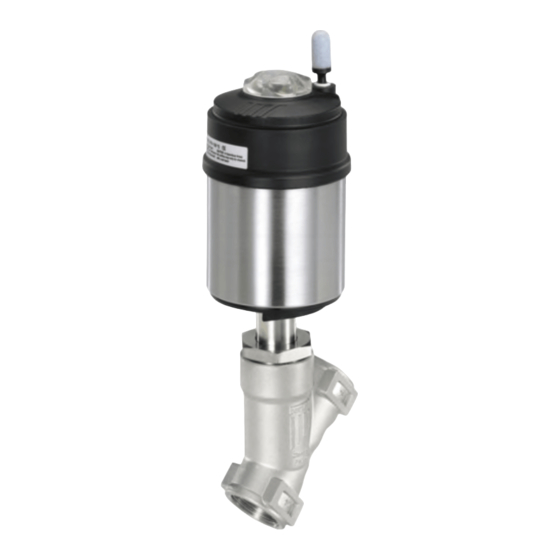
1 mm plug gauge. → Fig. 29: Angle seat valve Type 2100 If the authorisation also applies to stainless steel bodies, the same type of dirt trap must be attached in front of the angle seat valve. -
Page 28: Install Actuator (Welded Body)
Type 2100 Installation → 8.4 Install actuator (welded body) Control function A pressurize the pilot air port 1 with compressed air (5 bar): valve opens. → Screw actuator into the valve body. Observe tightening torque “Tab. 19”. Seal Air discharge connection CFA, CFB... -
Page 29: Install Control Unit
Type 2100 Installation 8.5 Install control unit WARNING! Risk of injury from discharge of medium and pressure. Description see Installation chapter in the operating instruc- tions for the corresponding control unit. If the direction of rotation is wrong, the body interface may become detached. 8.6 Rotating the actuator ▶ Rotate the actuator module in the specified direction only (see “Fig. -
Page 30: Pneumatic Connection
Type 2100 Installation 8.7 Pneumatic connection Control function I: → Connect the control medium to the pilot air port 1 and 2 of the WARNING! actuator (see “Fig. 33”) Pressure on connection 1 opens the valve. Risk of injury from unsuitable connection hoses. Pressure on connection 2 closes the valve. -
Page 31: Start-Up
8.8 Start-up After installing the device, run the teach function. This function The valve Type 2100 can be combined with following control units: presets the control parameters. • Type 8690 Pneumatic Control Unit (actuator size ∅ 70 - ∅ 130) •... -
Page 32: Maintenance, Cleaning
Type 2100 Maintenance,cleaning MAINTENANCE, CLEANING WARNING! DANGER! For control function I – Danger if pilot pressure fails. For control function I control and resetting occur pneumatically. If Danger – high pressure in the equipment. the pressure fails, no defined position is reached. ▶ Before loosening the lines and valves, turn off the pressure and ▶ To ensure a controlled restart, first pressurize the device with vent the lines. -
Page 33: Replacing The Valve Set
Type 2100 Maintenance,cleaning 10.2 Replacing the valve set Visual inspection: Perform regular visual inspections according to the application The valve set consists of conditions: • Swivel plate → Check media connections for leaks. • Pin → Check release bore on the tube for leaks. - Page 34 Type 2100 Maintenance,cleaning 10.2.1 Remove the actuator from the valve 10.2.2 Replacing valve set body → Clamp the valve body in a holding device (applies only to valves which have not yet been installed). NOTE! Spindle Damage to the seat seal or the seat contour. ▶ When removing the actuator, ensure that the valve is open.
- Page 35 Type 2100 Maintenance,cleaning → → Align bores of the swivel plate and spindle. Screw actuator into the valve body. Observe tightening torque → (see “Tab. 20”). Support swivel plate on the cylindrical part with the aid of a prism or something similar.
-
Page 36: Replacing The Packing Gland
Type 2100 Maintenance,cleaning 10.3 Replacing the packing gland 10.3.1 Remove the actuator from the valve body The seal set for the packing gland contains → Clamp the valve body in a holding device • 1 support ring • 1 spindle guide (applies only to valves which have not yet been installed). - Page 37 Type 2100 Maintenance,cleaning 10.3.2 Removing the swivel plate 10.3.3 Replacing packing gland → Knock out the pin with a suitable pin punch. Packing gland tube Pin punch ø 3 mm, for spindle diameter 10 mm on the swivel plate. Packing gland Pin punch ø 5 mm, for spindle diameter 14 mm on the swivel plate.
- Page 38 Type 2100 Maintenance,cleaning → Series production status up to January 2013 Push packing gland into the packing gland tube. → → Unscrew the spindle guide with the aid of the installation Screw spindle guide back in using the installation tool. Observe wrench and an open-end wrench.
- Page 39 Type 2100 Maintenance,cleaning 10.3.4 Installing swivel plate MALFUNCTIONS → Connect swivel plate to the spindle. Malfunction Reason Remedial action → Align bores of the swivel plate and spindle. Actuator Pilot air port Connecting pilot air → Support swivel plate on the cylindrical part with the aid of a...
-
Page 40: Replacement Parts
12.1 Replacement part sets too low The following replacement part sets are available for the angle seat Valve is Packing gland Renew packing gland or valve Type 2100: leaking on worn replace actuator • Valve set the release consists of swivel plate with PTFE seal, pin and seal. - Page 41 Type 2100 Replacementparts 1 Seal Valve set 2 Swivel plate Valve set Orifice Order no. 3 Pin 011 134 4 Sealing set for 011 171 packing gland 160 737 011 208 011 209 216 431 50 (Actuator size ø 70) 307 392 241 777 Tab.
-
Page 42: Installation Tools
Type 2100 Packaging,transport,storage 12.2 Installation tools PACKAGING, TRANSPORT, STORAGE Installation wrench for packing gland (Only for removal of packing glands up to January 2013) NOTE! Installation wrench Orifice Order no. Transport damages. Spindle ∅ 10 mm 15–40 665 700 Inadequately protected equipment may be damaged during Spindle ∅ 14 mm 32–65... - Page 43 www.burkert.com...
Need help?
Do you have a question about the 2100 and is the answer not in the manual?
Questions and answers