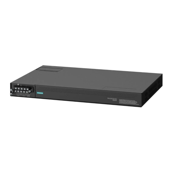
Siemens RUGGEDCOM RS416 Installation Manual
Hide thumbs
Also See for RUGGEDCOM RS416:
- Installation manual (50 pages) ,
- Installation manual (52 pages)

Related Manuals for Siemens RUGGEDCOM RS416


Summary of Contents for Siemens RUGGEDCOM RS416
- Page 1 Preface Introduction Installing Device RUGGEDCOM RS416 Communication Ports Technical Specifications Dimension Drawings Installation Guide Certification 6/2013 RC1018-EN-02...
-
Page 2: Security Information
Warranty Siemens warrants this product for a period of five (5) years from the date of purchase, conditional upon the return to factory for maintenance during the warranty term. This product contains no user-serviceable parts. Attempted service by unauthorized personnel shall render all warranties null and void. -
Page 3: Table Of Contents
RUGGEDCOM RS416 Installation Guide Table of Contents Table of Contents Preface ........................ Alerts ..............................v Related Documents ..........................v Accessing Documentation ........................v Training .............................. vi Customer Support ..........................vi Chapter 1 Introduction ......................1.1 Feature Highlights ........................1 1.2 Ports, Controls and Indicator LEDs ....................3 Chapter 2 Installing Device .................... - Page 4 RUGGEDCOM RS416 Table of Contents Installation Guide 3.5.2 IRIG-B Connection Considerations ................... 24 Chapter 4 Technical Specifications ..................4.1 Power Supply Specifications ....................... 25 4.2 Failsafe Relay Specifications ...................... 25 4.3 Copper Ethernet Port Specifications .................... 26 4.4 Fiber Optic Ethernet Port Specifications ..................26 4.4.1 10Base-FL Ethernet Optical Specifications ................
-
Page 5: Preface
Installation Guide Preface Preface This guide describes the RUGGEDCOM RS416. It describes the major features of the device, installation, commissioning and important technical specifications. It is intended for use by network technical support personnel who are responsible for the installation, commissioning and maintenance of the device. -
Page 6: Training
Siemens sales representative. Customer Support Customer support is available 24 hours, 7 days a week for all Siemens customers. For technical support or general information, please contact Siemens Customer Support through any of the following methods: • Online Visit http://www.siemens.com/automation/support-request... -
Page 7: Introduction
Introduction Introduction The RUGGEDCOM RS416 is an industrially hardened serial device server with an integrated, fully managed, Ethernet switch, designed to operate reliably in electrically harsh and climatically demanding environments. Featuring a modular design that can support IEEE 1588 and IRIG-B time synchronization, up to 16 serial ports and up to four Ethernet ports, the RS416 is able to interconnect and synchronize multiple types of intelligent electronic devices (IEDs). - Page 8 Chapter 1 RUGGEDCOM RS416 Introduction Installation Guide Ethernet Ports • Integrated Ethernet switch • Copper or fiber options • Supports IEEE 1588 v2 • Non-blocking, store and forward switching IRIG-B Option • Conversion from IEEE 1588 v2 • One IRIG-B PWM/PPS Output •...
-
Page 9: Ports, Controls And Indicator Leds
RUGGEDCOM RS416 Chapter 1 Installation Guide Introduction • CSA/UL 60950-1 safety approved to 85 °C (185 °F) Management Tools • Web-based, Telnet, CLI management interfaces • SNMP v1, v2 and v3 • Remote Monitoring (RMON) • Rich set of diagnostics with logging and alarms Section 1.2... - Page 10 Chapter 1 RUGGEDCOM RS416 Introduction Installation Guide Display Mode Indicator LEDs These LEDs indicate the current display mode for the port status indicator LEDs (i.e. Status, Duplex or Speed). Mode button The Mode button sets the display mode for the port status indicator LEDs (i.e. Status, Duplex or Speed).
-
Page 11: Installing Device
This product contains no user-serviceable parts. Attempted service by unauthorized personnel shall render all warranties null and void. Changes or modifications not expressly approved by Siemens Canada Ltd. could invalidate specifications, test results, and agency approvals, and void the user's authority to operate the equipment. -
Page 12: Mounting The Device To A Rack
Chapter 2 RUGGEDCOM RS416 Installing Device Installation Guide NOTE For detailed dimensions of the device with either rack, DIN rail or panel hardware installed, refer to Chapter 5, Dimension Drawings. The following sections describe the various methods of mounting the device: •... -
Page 13: Mounting The Device On A Din Rail
RUGGEDCOM RS416 Chapter 2 Installation Guide Installing Device Secure the adapters to the rack using the supplied hardware. Section 2.1.2 Mounting the Device on a DIN Rail For DIN rail installations, the RS416 can be equipped with panel/DIN rail adapters pre-installed on each side of the chassis. -
Page 14: Connecting Power
Chapter 2 RUGGEDCOM RS416 Installing Device Installation Guide Figure 4: Panel Mounting 1. Screw 2. Panel/DIN Rail Adaptor Install the supplied screws to secure the adapters to the panel. Section 2.2 Connecting Power The RS416 supports single or dual redundant high AC and/or low DC power supplies. The use of two power modules is recommended to provide redundancy and load balancing. -
Page 15: Connecting Ac Power
RUGGEDCOM RS416 Chapter 2 Installation Guide Installing Device • It is recommended to provide a separate circuit breaker for each power supply module. • Equipment must be installed according to applicable local wiring codes and standards. The following sections describe how to connect power to the device: •... -
Page 16: Connecting Dc Power
Chapter 2 RUGGEDCOM RS416 Installing Device Installation Guide Figure 5: Terminal Block Wiring 1. Screw-Type Terminal Block 2. Pluggable Terminal Block 3. Jumper 4. Positive/Live (+/L) Terminal 5. Negative/Neutral (-/N) Terminal (-/N) 6. Surge Ground Terminal 7. Chassis Ground Terminal Connect the negative wire from the power source to the negative/neutral (-/N) terminal on the terminal block. -
Page 17: Wiring Examples
RUGGEDCOM RS416 Chapter 2 Installation Guide Installing Device Remove the terminal block cover. If a screw-type terminal block is installed, remove the screws from the appropriate terminals. Use these screws along with #6 ring lugs to secure the wires to the terminal block. - Page 18 Chapter 2 RUGGEDCOM RS416 Installing Device Installation Guide Figure 7: Single AC Power Supply Figure 8: Single DC Power Supply Wiring Examples...
- Page 19 RUGGEDCOM RS416 Chapter 2 Installation Guide Installing Device Figure 9: Dual AC Power Supply Figure 10: Dual DC Power Supply Wiring Examples...
-
Page 20: Connecting The Failsafe Alarm Relay
Chapter 2 RUGGEDCOM RS416 Installing Device Installation Guide Figure 11: Dual AC/DC Power Supply Section 2.3 Connecting the Failsafe Alarm Relay The failsafe relay can be configured to latch based on alarm conditions. The NO (Normally Open) contact is closed when the unit is powered and there are no active alarms. If the device is not powered or if an active alarm is configured, the relay opens the NO contact and closes the NC (Normally Closed) contact. -
Page 21: Grounding The Device
RUGGEDCOM RS416 Chapter 2 Installation Guide Installing Device Figure 12: Failsafe Alarm Relay Wiring 1. Screw-Type Terminal Block 2. Pluggable Terminal Block 3. Normally Open Terminal 4. Common Terminal 5. Normally Closed Terminal Section 2.4 Grounding the Device The RS416 chassis ground terminal uses a #6-32 screw. It is recommended to terminate the ground connection with a #6 ring lug and torque it to 1.7 N·m (15 lbf·in). -
Page 22: Cabling Recommendations
Section 2.6 Cabling Recommendations Siemens does not recommend the use of copper cabling of any length for critical, real-time substation automation applications. All copper Ethernet ports on RUGGEDCOM products include transient suppression circuitry to protect against damage from electrical transients and conform with IEC 61850-3 and IEEE 1613 Class 1 standards. -
Page 23: Communication Ports
RUGGEDCOM RS416 Chapter 3 Installation Guide Communication Ports Communication Ports The RS416 can be equipped with various types of communication ports to enhance its abilities and performance. To determine which ports are equipped on the device, refer to the factory data file available through ROS. For more information on how to access the factory data file, refer to the ROS User Guide for the RS416. -
Page 24: Fiber Optic Ethernet Ports
Chapter 3 RUGGEDCOM RS416 Communication Ports Installation Guide State Description The port is operating at 10 Mbps Link Yellow (Solid) Link established Yellow (Blinking) Link activity No link detected The following is the pin-out for the RJ45 male connector: Name... -
Page 25: Serial Ports
RUGGEDCOM RS416 Chapter 3 Installation Guide Communication Ports Figure 19: SC Port Figure 20: ST Port 1. Tx Connector 2. Rx Connector 1. Tx Connector 2. Rx Connector For specifications on the available fiber optic Ethernet ports, refer to Section 4.4, “Fiber Optic Ethernet Port Specifications”. - Page 26 Chapter 3 RUGGEDCOM RS416 Communication Ports Installation Guide Serial DB9 Port Mode RS232 DCE RS485 RS422 TX/RX+ Common (Isolated) Ground Figure 22: Serial DB9 Port Pin Configuration TX/RX- Shield Chassis Ground The DSR, DCD and DTR pins are connected together internally.
- Page 27 RUGGEDCOM RS416 Chapter 3 Installation Guide Communication Ports NOTE Pins 7 and 8 are connected internally. In RS232 mode, these pins enter a high impedance state. A DTE that asserts RTS will see CTS asserted. However, the device will not perform hardware flow control.
-
Page 28: Connecting Multiple Rs485 Devices
Chapter 3 RUGGEDCOM RS416 Communication Ports Installation Guide NOTE Pins 7 and 8 are connected internally. In RS232 mode, these pins enter a high impedance state. A DTE that asserts RTS will see CTS asserted. However, the device will not perform hardware flow control. -
Page 29: Time Synchronization
RUGGEDCOM RS416 Chapter 3 Installation Guide Communication Ports Section 3.5 Time Synchronization The RS416 is able to derive and provide time synchronization via Ethernet using the Precision Time Protocol (PTP) and NTP (Network Time Protocol). With the IRIG-B module is installed, the RS416 is also able to synchronize to received IRIG-B time signal and to distribute it via BNC and via serial ports equipped with IRIG-B signals. -
Page 30: Irig-B Connection Considerations
Chapter 3 RUGGEDCOM RS416 Communication Ports Installation Guide Figure 27: IRIG-B Daughter Board BNC Connections LED Color Meaning No IRIG-B signal detected Errors detected in received IRIG-B signal Green Received IRIG-B signal is good Section 3.5.2 IRIG-B Connection Considerations The number of IRIG-B devices that can be connected to a given IRIG-B output is dependent on the cabling type and length, as well as the input impedances of connected devices. -
Page 31: Technical Specifications
RUGGEDCOM RS416 Chapter 4 Installation Guide Technical Specifications Technical Specifications The following sections provide important technical specifications related to the device and available modules: • Section 4.1, “Power Supply Specifications” • Section 4.2, “Failsafe Relay Specifications” • Section 4.3, “Copper Ethernet Port Specifications”... -
Page 32: Copper Ethernet Port Specifications
Chapter 4 RUGGEDCOM RS416 Technical Specifications Installation Guide Section 4.3 Copper Ethernet Port Specifications The following details the specifications for copper Ethernet ports that can be ordered with the RS416. Wiring Maximum Speed Connector Duplex Cable Type Isolation Standard Distance... -
Page 33: Serial Port Specifications
RUGGEDCOM RS416 Chapter 4 Installation Guide Technical Specifications Power Connector Cable Tx λ (typ.) Tx min. Tx max. Distance Mode Sensitivity Saturation Budget Type Type (μm) (nm) (dBm) (dBm) (typ.) (km) (dBm) (dBm) (dB) 50/125 -22.5 62.5/125 MTRJ 1300 50/125 -22.5... -
Page 34: Fiber Serial Port Specifications
Chapter 4 RUGGEDCOM RS416 Technical Specifications Installation Guide Section 4.5.2 Fiber Serial Port Specifications Optical Mode Connector Typical Distance (km) Cable Size Wavelength (nm) 50/125 Multimode 62.5/125 Section 4.6 IRIG-B Ports Table: IRIG-B PWM Input Parameter Typical Value Input Voltage... -
Page 35: Dimension Drawings
RUGGEDCOM RS416 Chapter 5 Installation Guide Dimension Drawings Dimension Drawings NOTE All dimensions are in millimeters, unless otherwise stated. 438.15 Figure 29: Overall Dimensions... - Page 36 Chapter 5 RUGGEDCOM RS416 Dimension Drawings Installation Guide 479.30 461.01 11.68 21.08 32.64 4.57 Figure 30: Rack Mount Dimensions...
- Page 37 RUGGEDCOM RS416 Chapter 5 Installation Guide Dimension Drawings 486.4 476.3 10.4 11.7 Figure 31: Panel and DIN Rail Mount Dimensions...
- Page 38 RUGGEDCOM RS416 Chapter 5 Installation Guide Dimension Drawings...
-
Page 39: Certification
RUGGEDCOM RS416 Chapter 6 Installation Guide Certification Certification The RS416 device has been thoroughly tested to guarantee its conformance with recognized standards and has received approval from recognized regulatory agencies. • Section 6.1, “Agency Approvals” • Section 6.2, “FCC Compliance”... -
Page 40: Emi And Environmental Type Tests
Chapter 6 RUGGEDCOM RS416 Certification Installation Guide Section 6.4 EMI and Environmental Type Tests The RS416 has passed the following EMI and environmental tests. IEC 61850-3 Type Tests Test Description Test Levels Severity Levels IEC 61000-4-2 Enclosure +/- 8 kV... - Page 41 5 kV (Fail-Safe Relay Output) DC Power ports 5 kV AC Power ports 5 kV Siemens specified severity level. IEEE 1613 (C37.90.x) EMI Immunity Type Tests NOTE The RS416 meets Class 2 requirements for an all-fiber configuration and Class 1 requirements for copper ports.
- Page 42 Chapter 6 RUGGEDCOM RS416 Certification Installation Guide Test Description Test Levels Severity Levels IEC 60068-2-2 Dry Heat Test Bd 85 °C (185 °F), 16 Hours IEC 60068-2-30 Humidity (Damp Test Db 95% (non-condensing), Heat, Cyclic) 55 °C (131 °F), 6 cycles...
Need help?
Do you have a question about the RUGGEDCOM RS416 and is the answer not in the manual?
Questions and answers