Siemens RUGGEDCOM RS910 Installation Manual
Hide thumbs
Also See for RUGGEDCOM RS910:
- Installation manual (36 pages) ,
- Installation manual (52 pages) ,
- Installation manual (52 pages)

Related Manuals for Siemens RUGGEDCOM RS910


Summary of Contents for Siemens RUGGEDCOM RS910
- Page 1 Preface Introduction Installing the Device RUGGEDCOM RS910 Communication Ports Technical Specifications Dimension Drawings Installation Guide Certification 10/2016 RC1029-EN-03...
-
Page 2: Security Information
Warranty Siemens warrants this product for a period of five (5) years from the date of purchase, conditional upon the return to factory for maintenance during the warranty term. This product contains no user-serviceable parts. Attempted service by unauthorized personnel shall render all warranties null and void. - Page 3 RUGGEDCOM RS910 Installation Guide Contacting Siemens Address Telephone E-mail Siemens Canada Ltd Toll-free: 1 888 264 0006 ruggedcom.info.i-ia@siemens.com Industry Sector Tel: +1 905 856 5288 300 Applewood Crescent Fax: +1 905 856 1995 Concord, Ontario www.siemens.com/ruggedcom Canada, L4K 5C7...
- Page 4 RUGGEDCOM RS910 Installation Guide...
-
Page 5: Table Of Contents
RUGGEDCOM RS910 Installation Guide Table of Contents Table of Contents Preface ......................Alerts ..............................vii Related Documents ..........................vii Accessing Documentation ........................viii Training ............................viii Customer Support ..........................viii Chapter 1 Introduction ..................... 1.1 Feature Highlights ........................1 1.2 Description ........................... 2 Chapter 2 Installing the Device .................. - Page 6 RUGGEDCOM RS910 Table of Contents Installation Guide 4.3 Copper Ethernet Port Specifications ....................22 4.4 Fiber Optic Ethernet Port Specifications ..................22 4.5 Serial Port Specifications ......................24 4.5.1 Copper Serial Port Specifications ..................24 4.5.2 Fiber Serial Port Specifications ..................24 4.6 Operating Environment ....................... 24 4.7 Mechanical Specifications ......................
-
Page 7: Preface
Installation Guide Preface Preface This guide describes the RUGGEDCOM RS910. It describes the major features of the device, installation, commissioning and important technical specifications. It is intended for use by network technical support personnel who are responsible for the installation, commissioning and maintenance of the device. -
Page 8: Accessing Documentation
Siemens Sales representative. Customer Support Customer support is available 24 hours, 7 days a week for all Siemens customers. For technical support or general information, contact Siemens Customer Support through any of the following methods: Online Visit http://www.siemens.com/automation/support-request... -
Page 9: Introduction
RUGGEDCOM RS910 to be placed in almost any location. The RUGGEDCOM RS910 can be mounted on a DIN rail or panel for efficient use of cabinet space. The integrated power supply supports a wide range of voltages (88-300 VDC or 85-264 VAC) for worldwide operability, as well as dual-redundant, reversible polarity, 24 VDC and 48 VDC power supply inputs for high availability applications requiring dual or backup power inputs. -
Page 10: Description
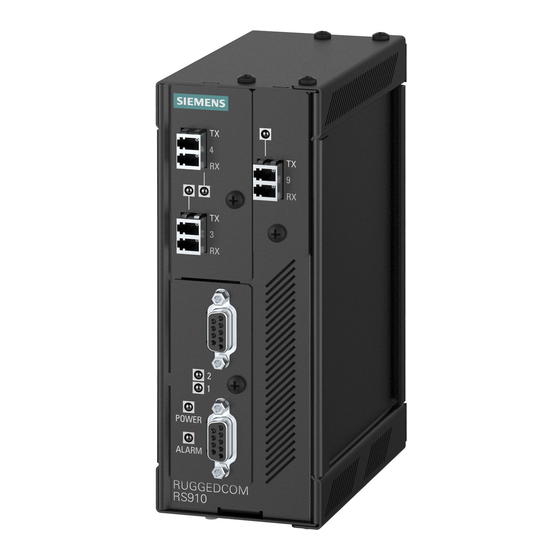
• Terminal blocks for reliable maintenance free connections • CSA/UL 60950-1 safety approved to 85 °C (185 °F) Section 1.2 Description The RUGGEDCOM RS910 features various ports, controls and indicator LEDs on the front panel for connecting, configuring and troubleshooting the device. Description... - Page 11 Section 2.5, “Connecting to the Device” Communication Ports Receive and transmit data, as well as provide access to the RUGGEDCOM ROS Web interface. For more information about the various ports available for the RUGGEDCOM RS910, refer to Chapter 3, Communication Ports Failsafe Alarm Relay Latches to default state when a power disruption or other alarm condition occurs.
- Page 12 RUGGEDCOM RS910 Chapter 1 Installation Guide Introduction Description...
-
Page 13: Installing The Device
This product contains no user-serviceable parts. Attempted service by unauthorized personnel shall render all warranties null and void. Changes or modifications not expressly approved by Siemens Canada Ltd could invalidate specifications, test results, and agency approvals, and void the user's authority to operate the equipment. -
Page 14: Required Tools And Materials
Section 2.2 Mounting the Device The RUGGEDCOM RS910 is designed for maximum mounting and display flexibility. It can be equipped with adapters that allow it to be installed on a 35 mm (1.4 in) DIN rail or affixed to a panel. -
Page 15: Mounting The Device To A Panel
Mounting the Device to a Panel For panel installations, the RUGGEDCOM RS910 can be equipped with panel adapters pre-installed on the top and bottom of the chassis. The adapters allow the device to be attached to a panel using screws. -
Page 16: Connecting Power
Secure the adapters to the panel with #6-32 screws. Section 2.3 Connecting Power The RUGGEDCOM RS910 supports power input from a single high AC/DC or low DC power supply. IMPORTANT! • For 110/230 VAC rated equipment, an appropriately rated AC circuit breaker must be installed. -
Page 17: Connecting High Ac/Dc Power
RUGGEDCOM RS910 Chapter 2 Installation Guide Installing the Device • Section 2.3.2, “Connecting Low DC Power” Section 2.3.1 Connecting High AC/DC Power To connect a high AC/DC power supply to the device, do the following: CAUTION! Electrical hazard – risk of damage to equipment. Do not connect AC power cables to terminals for DC power. -
Page 18: Connecting Low Dc Power
Section 2.3.2 Connecting Low DC Power RUGGEDCOM RS910's equipped with 24 or 48 V power supply inputs feature reverse polarity protection and dual power supply inputs allowing the device to accept redundant connections to a single DC power supply. To connect a low DC power supply to the device, do the following: NOTE Torque all terminal connections to 0.6 N·m (5 lbf-in). -
Page 19: Connecting The Failsafe Alarm Relay
Control of the failsafe relay output is configurable through ROS. One common application for this relay is to signal an alarm if a power failure occurs. For more information, refer to the ROS User Guide for the RUGGEDCOM RS910. The following shows the proper relay connections. -
Page 20: Connecting To The Device
Connecting to the Device The following describes the various methods for accessing the ROS console and Web interfaces on the device. For more detailed instructions, refer to the ROS User Guide for the RUGGEDCOM RS910. IMPORTANT! Ethernet cables should be only be connected/disconnected in a non-hazardous area, or when the device is not energized. -
Page 21: Cabling Recommendations
Siemens also does not recommend using copper Ethernet ports to interface with devices in the field across distances that could produce high levels of ground potential rise (i.e. greater than 2500 V), during line-to-ground fault conditions. - Page 22 RUGGEDCOM RS910 Chapter 2 Installation Guide Installing the Device Cabling Recommendations...
-
Page 23: Communication Ports
RUGGEDCOM RS910 Chapter 3 Installation Guide Communication Ports Communication Ports The RUGGEDCOM RS910 can be equipped with various types of communication ports to enhance its abilities and performance. Figure 9: Port Assignment 1. Ports 1 and 2 2. Ports 3 and 4 3. Port 9 Port... -
Page 24: Specifications
Chapter 3 RUGGEDCOM RS910 Communication Ports Installation Guide WARNING! Electric shock hazard – risk of serious personal injury and/or equipment interference. If shielded cables are used, make sure the shielded cables do not form a ground loop via the shield wire and the RJ-45 receptacles at either end. -
Page 25: Fiber Optic Ethernet Ports
RUGGEDCOM RS910 Chapter 3 Installation Guide Communication Ports Section 3.2 Fiber Optic Ethernet Ports Fiber optic Ethernet ports are available with either MTRJ (Mechanical Transfer Registered Jack), LC (Lucent Connector), SC (Standard or Subscriber Connector) or ST (Straight Tip) connectors. Make sure the Transmit (Tx) and Receive (Rx) connections of each port are properly connected and matched to establish a proper link. -
Page 26: Serial Ports
Installation Guide Section 3.3 Serial Ports The RUGGEDCOM RS910 supports DB9, RJ-45 and ST (Straight Tip) fiber serial ports, all of which can be run in RS232, RS485 or RS422 mode. NOTE On power-up, all serial ports default to RS485 mode. Each port can be individually set to RS232, RS485 or RS422 mode through RUGGEDCOM ROS. -
Page 27: Connecting Multiple Rs485 Devices
RUGGEDCOM RS910 Chapter 3 Installation Guide Communication Ports RS232 Mode RS485 Mode RS422 Mode DSR/RI Common (Isolated) Ground Figure 17: Serial RJ-45 Port TX/RX+ TX/RX- Shield Chassis Ground No internal termination is provided. Connected internally. Connected internally. In RS232 mode, this pin enters a high impedance state. A DTE that asserts RTS will see CTS asserted, although the device will not perform hardware flow control. - Page 28 • The twisted pair should be terminated at each end of the chain. The following shows the recommended RS485 wiring. 120Ω 10nF 120Ω 10nF Figure 19: Recommended RS485 Wiring 1. RUGGEDCOM RS910 Device 2. Common (Isolated Ground) 3. Negative 4. Positive 5. Shield to Earth (Connected At a Single Point) 6. RS485 Devices (32 Total) Connecting Multiple RS485 Devices...
-
Page 29: Technical Specifications
RUGGEDCOM RS910 Chapter 4 Installation Guide Technical Specifications Technical Specifications This section provides important technical specifications related to the device. CONTENTS • Section 4.1, “Power Supply Specifications” • Section 4.2, “Failsafe Relay Specifications” • Section 4.3, “Copper Ethernet Port Specifications” • Section 4.4, “Fiber Optic Ethernet Port Specifications”... -
Page 30: Copper Ethernet Port Specifications
Section 4.4 Fiber Optic Ethernet Port Specifications The following details the specifications for fiber Ethernet ports that can be ordered with the RUGGEDCOM RS910. NOTE • All optical power numbers are listed as dBm averages. To convert from average to peak add 3 dBm. - Page 31 RUGGEDCOM RS910 Chapter 4 Installation Guide Technical Specifications Tx (dBm) Power Connector Cable Distance Mode Tx λ (nm) Sensitivity Saturation Budget Type Type (μm) (km) Minimum Maximum (dBm) (dBm) (dB) 62.5/125 -33.5 14.5 50/125 -22.5 -33.9 11.4 1300 62.5/125 -33.9 14.9...
-
Page 32: Serial Port Specifications
Chapter 4 RUGGEDCOM RS910 Technical Specifications Installation Guide Section 4.5 Serial Port Specifications This section details specifications for ports that can be equipped on the RS910. CONTENTS • Section 4.5.1, “Copper Serial Port Specifications” • Section 4.5.2, “Fiber Serial Port Specifications” Section 4.5.1 Copper Serial Port Specifications... -
Page 33: Mechanical Specifications
RUGGEDCOM RS910 Chapter 4 Installation Guide Technical Specifications Section 4.7 Mechanical Specifications Parameter Value Dimensions Refer to Chapter 5, Dimension Drawings Weight 1.2 kg (2.7 lbs) Ingress Protection IP40 (1 mm or 0.04 in objects) Enclosure 20 AWG Galvanized Steel Mechanical Specifications... - Page 34 RUGGEDCOM RS910 Chapter 4 Installation Guide Technical Specifications Mechanical Specifications...
-
Page 35: Dimension Drawings
RUGGEDCOM RS910 Chapter 5 Installation Guide Dimension Drawings Dimension Drawings NOTE All dimensions are in millimeters, unless otherwise stated. 116.59 65.13 7.87 Figure 20: Overall Dimensions... - Page 36 Chapter 5 RUGGEDCOM RS910 Dimension Drawings Installation Guide 130.4 13.64 101.6 11.2 78.74 120.65 Figure 21: Panel and DIN Rail Mount Dimensions...
-
Page 37: Certification
60950-1) • UL 60950-1 Information Technology Equipment – Safety Part 1: General Requirements Section 6.1.2 European Union (EU) This device is declared by Siemens Canada Ltd to comply with essential requirements and other relevant provisions of the following EU directives: Approvals... -
Page 38: Fcc
Information Technology Equipment – Radio Disturbance Characteristics – Limits and Methods of Measurement The device is marked with a CE marking and can be used throughout the European community. A copy of the CE Declaration of Conformity is available from Siemens Canada Ltd. For contact information, refer to “Contacting Siemens ”... -
Page 39: Other Approvals
• IEC 61850-3 Communication Networks and Systems in Substations – Part 3: General Requirements Section 6.2 EMC and Environmental Type Tests The RUGGEDCOM RS910 has passed the following Electromagnetic Compatibility (EMC) and environmental tests. EMC Type Tests Test Description Test Levels... - Page 40 EMC Immunity Type Tests per IEEE 1613 NOTE The RUGGEDCOM RS910 meets Class 2 requirements for an all-fiber configuration and Class 1 requirements for copper ports. Class 1 allows for temporary communication loss, while Class 2 requires error-free and interrupted communications.
- Page 41 RUGGEDCOM RS910 Chapter 6 Installation Guide Certification Description Test Levels Oscillatory Signal Ports 2.5 kV Common Mode @ 1 MHz DC Power Ports 2.5 kV Common and Differential Mode @ 1 MHz AC Power Ports 2.5 kV Common and Differential Mode @ 1 MHz...
- Page 42 RUGGEDCOM RS910 Chapter 6 Installation Guide Certification EMC and Environmental Type Tests...
Need help?
Do you have a question about the RUGGEDCOM RS910 and is the answer not in the manual?
Questions and answers