Siemens RUGGEDCOM RS910 Installation Manual
Hide thumbs
Also See for RUGGEDCOM RS910:
- Installation manual (42 pages) ,
- Installation manual (52 pages) ,
- Installation manual (52 pages)

Subscribe to Our Youtube Channel
Related Manuals for Siemens RUGGEDCOM RS910


Summary of Contents for Siemens RUGGEDCOM RS910
- Page 1 Preface Introduction Installing the Device RUGGEDCOM RS910 Communication Ports Technical Specifications Dimension Drawings Installation Guide Certification 9/2013...
-
Page 2: Security Information
Warranty Siemens warrants this product for a period of five (5) years from the date of purchase, conditional upon the return to factory for maintenance during the warranty term. This product contains no user-serviceable parts. Attempted service by unauthorized personnel shall render all warranties null and void. -
Page 3: Table Of Contents
RUGGEDCOM RS910 Installation Guide Table of Contents Table of Contents Preface ........................ Alerts ..............................v Related Documents ..........................v Accessing Documentation ........................v Training .............................. vi Customer Support ..........................vi Chapter 1 Introduction ......................1.1 Feature Highlights ........................1 1.2 Ports, Controls and Indicator LEDs ....................2 Chapter 2 Installing the Device .................... - Page 4 RUGGEDCOM RS910 Table of Contents Installation Guide 4.4 10Base-FL Fiber Optic Ethernet Port Specifications ..............20 4.5 Fiber Optic Ethernet Port Specifications ..................20 4.6 Serial Port Specifications ......................21 4.6.1 Copper Serial Port Specifications ..................22 4.6.2 Fiber Serial Port Specifications ..................22 4.7 Operating Environment .......................
-
Page 5: Preface
Installation Guide Preface Preface This guide describes the RUGGEDCOM RS910. It describes the major features of the device, installation, commissioning and important technical specifications. It is intended for use by network technical support personnel who are responsible for the installation, commissioning and maintenance of the device. -
Page 6: Training
Siemens sales representative. Customer Support Customer support is available 24 hours, 7 days a week for all Siemens customers. For technical support or general information, please contact Customer Support at: Toll Free (North America): 1 866 922 7975... -
Page 7: Introduction
Introduction Introduction The RUGGEDCOM RS910 is an industrially hardened serial device server with an integrated, fully managed, Ethernet switch, designed to operate reliably in electrically harsh and climatically demanding environments. The RS910 can be configured with two serial ports (RS485/RS422/RS232) and/or up to three Ethernet ports (copper or fiber). -
Page 8: Ports, Controls And Indicator Leds
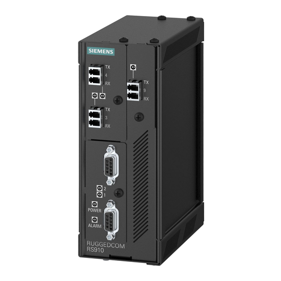
Chapter 1 RUGGEDCOM RS910 Introduction Installation Guide Cyber Security • Multi-level user passwords • SSH/SSL (128-bit encryption) • Enable/disable ports, MAC based port security • Port based network access control (802.1x) • VLAN (802.1Q) to segregate and secure network traffic •... - Page 9 RUGGEDCOM RS910 Chapter 1 Installation Guide Introduction Figure 1: Front Panel 1. Power Indicator LEDs 2. Alarm Indicator LED 3. RS232 Serial Console Port Power Indicator LEDs The power indicator LED illuminates when power is being supplied to the device.
- Page 10 RUGGEDCOM RS910 Chapter 1 Installation Guide Introduction Ports, Controls and Indicator LEDs...
-
Page 11: Installing The Device
This product contains no user-serviceable parts. Attempted service by unauthorized personnel shall render all warranties null and void. Changes or modifications not expressly approved by Siemens AG could invalidate specifications, test results, and agency approvals, and void the user's authority to operate the equipment. -
Page 12: Mounting The Device On A Din Rail
Chapter 2 RUGGEDCOM RS910 Installing the Device Installation Guide • Section 2.1.1, “Mounting the Device on a DIN Rail” • Section 2.1.2, “Mounting the Device to a Panel” Section 2.1.1 Mounting the Device on a DIN Rail For DIN rail installations, the RS910 can be equipped with a DIN rail bracket pre-installed on the back of the chassis. -
Page 13: Connecting Power
Ground. Note that all line-to-ground transient protection circuitry will be disabled. IMPORTANT! Siemens requires the use of external surge protection in VDSL applications where the line may be subject to surges greater than that for which the device is rated. Use the following specifications as a guide for VDSL external surge protection: •... -
Page 14: Connecting High Ac/Dc Power
Chapter 2 RUGGEDCOM RS910 Installing the Device Installation Guide • Insertion Loss: < 0.1 dB at 10 MHz • Peak Surge Current: 10 kA, 8x20µs waveform The following sections describe how to connect power to the device: • Section 2.2.1, “Connecting High AC/DC Power”... -
Page 15: Connecting Low Dc Power
RUGGEDCOM RS910 Chapter 2 Installation Guide Installing the Device Figure 4: Terminal Block Wiring 1. Positive/Live (+/L) Terminal 2. Negative/Neutral (-/N) Terminal 3. Surge Ground Terminal 4. Braided Ground Cable Connect the negative wire from the power source to the negative/neutral (-/N) terminal on the terminal block. -
Page 16: Connecting The Failsafe Alarm Relay
Chapter 2 RUGGEDCOM RS910 Installing the Device Installation Guide Figure 5: Terminal Block Wiring 1. Positive Terminal 2. Negative Terminal 3. Surge Ground Terminal 4. Braided Ground Cable Connect the negative wire from the power source to the negative terminal on the terminal block. -
Page 17: Connecting To The Device
RUGGEDCOM RS910 Chapter 2 Installation Guide Installing the Device Figure 6: Failsafe Alarm Relay Wiring 1. Normally Open 2. Common 3. Normally Closed Section 2.4 Connecting to the Device The following describes the various methods for accessing the ROS console and Web interfaces on the device. -
Page 18: Cabling Recommendations
Section 2.5 Cabling Recommendations Siemens does not recommend the use of copper cabling of any length for critical, real-time substation automation applications. All copper Ethernet ports on RUGGEDCOM products include transient suppression circuitry to protect against damage from electrical transients and conform with IEC 61850-3 and IEEE 1613 Class 1 standards. -
Page 19: Communication Ports
RUGGEDCOM RS910 Chapter 3 Installation Guide Communication Ports Communication Ports The RS910 can be equipped with various types of communication ports to enhance its abilities and performance. To determine which ports are equipped on the device, refer to the factory data file available through ROS. For more information on how to access the factory data file, refer to the ROS User Guide for the RS910. -
Page 20: Copper Ethernet Ports
Chapter 3 RUGGEDCOM RS910 Communication Ports Installation Guide Section 3.1 Copper Ethernet Ports The RS910 supports several 10/100Base-TX Ethernet ports that allow connection to standard Category 5 (CAT-5) unshielded twisted-pair (UTP) cables with RJ45 male connectors. The RJ45 receptacles are directly connected to the chassis ground on the device and can accept CAT-5 shielded twisted-pair (STP) cables. -
Page 21: Serial Ports
RUGGEDCOM RS910 Chapter 3 Installation Guide Communication Ports Figure 12: LC Port Figure 11: MTRJ Port 1. Tx Connector 2. Rx Connector 1. Tx Connector 2. Rx Connector Figure 13: SC Port Figure 14: ST Port 1. Tx Connector 2. Rx Connector 1. - Page 22 Chapter 3 RUGGEDCOM RS910 Communication Ports Installation Guide RS232 Mode RS485 Mode RS422 Mode TX/RX+ Common (Isolated Ground) TX/RX- Figure 15: Serial DB9 Port RI (No Connection) Shield Chassis Ground No internal termination is provided. The Common terminal is optically isolated. However, there is transient voltage protection circuitry between the Common terminal and chassis ground.
-
Page 23: Connecting Multiple Rs485 Devices
RUGGEDCOM RS910 Chapter 3 Installation Guide Communication Ports Figure 17: Serial SC Fiber Port 1. Tx Connector 2. Rx Connector Section 3.4 Connecting Multiple RS485 Devices Each RS485 port can communicate with multiple RS485 devices by wiring devices together in sequence over a single twisted pair with transmit and receive signals on the same two wires (half duplex). - Page 24 Chapter 3 RUGGEDCOM RS910 Communication Ports Installation Guide 120Ω 10nF 120Ω 10nF Figure 18: Recommended RS485 Wiring 1. RS910 Device 2. Common (Isolated Ground) 3. Negative 4. Positive 5. Shield to Earth (Connected At a Single Point) 6. RS485 Devices (32 Total)
-
Page 25: Technical Specifications
RUGGEDCOM RS910 Chapter 4 Installation Guide Technical Specifications Technical Specifications The following sections provide important technical specifications related to the device and available modules: • Section 4.1, “Power Supply Specifications” • Section 4.2, “Failsafe Relay Specifications” • Section 4.3, “Copper Ethernet Port Specifications”... -
Page 26: Copper Ethernet Port Specifications
To convert from peak to average, subtract 3 dBm. • Maximum segment length is greatly dependent on factors such as fiber quality, and the number of patches and splices. Consult a Siemens sales associate when determining maximum segment distances. Copper Ethernet Port Specifications... -
Page 27: Serial Port Specifications
RUGGEDCOM RS910 Chapter 4 Installation Guide Technical Specifications Cable Tx λ Distance Power Order Connector Tx min. Tx max. Mode Type (typ.) Sensitivity Saturation (typ.) Budget Code Type (dBm) (dBm) (μm) (nm) (dBm) (dBm) (km) (dB) 50/125 -22.5 -33.5 MTRJ 1300 62.5/125... -
Page 28: Copper Serial Port Specifications
Chapter 4 RUGGEDCOM RS910 Technical Specifications Installation Guide are contained within each unit when it is assembled and configured at the factory. For information about obtaining factory configuration data, refer to the ROS User Guide for the RS910. • Section 4.6.1, “Copper Serial Port Specifications”... - Page 29 RUGGEDCOM RS910 Chapter 4 Installation Guide Technical Specifications Parameter Value Enclosure 20 AWG Galvanized Steel Mechanical Specifications...
- Page 30 RUGGEDCOM RS910 Chapter 4 Installation Guide Technical Specifications Mechanical Specifications...
-
Page 31: Dimension Drawings
RUGGEDCOM RS910 Chapter 5 Installation Guide Dimension Drawings Dimension Drawings NOTE All dimensions are in millimeters, unless otherwise stated. 116.59 65.13 7.87 Figure 19: Overall Dimensions... - Page 32 Chapter 5 RUGGEDCOM RS910 Dimension Drawings Installation Guide 130.35 13.64 101.60 11.18 78.74 120.65 Figure 20: Panel and DIN Rail Mount Dimensions...
-
Page 33: Certification
RUGGEDCOM RS910 Chapter 6 Installation Guide Certification Certification The RS910 device has been thoroughly tested to guarantee its conformance with recognized standards and has received approval from recognized regulatory agencies. • Section 6.1, “Agency Approvals” • Section 6.2, “FCC Compliance”... -
Page 34: Emi And Environmental Type Tests
Chapter 6 RUGGEDCOM RS910 Certification Installation Guide Section 6.4 EMI and Environmental Type Tests The RS910 has passed the following EMI and environmental tests. IEC 61850-3 Type Tests Test Description Test Levels Severity Levels IEC 61000-4-2 Enclosure +/- 8 kV... - Page 35 RUGGEDCOM RS910 Chapter 6 Installation Guide Certification Test Description Test Levels Severity Levels IEC 60255-5 Dielectric Strength Signal ports 2 kVAC (Fail-Safe Relay output) DC Power ports 1.5 kVDC AC Power ports 2 kVDC HV Impulse Signal ports 5 kV (Fail-Safe Relay Output)
- Page 36 Chapter 6 RUGGEDCOM RS910 Certification Installation Guide Test Description Test Levels Severity Levels IEC 60068-2-30 Humidity (Damp Test Db 95% (non-condensing), Heat, Cyclic) 55 °C (131 °F), 6 cycles IEC 60255-21-1 Vibration 2 g @ 10-150 Hz Class 2 IEC 60255-21-2...
Need help?
Do you have a question about the RUGGEDCOM RS910 and is the answer not in the manual?
Questions and answers