
Related Manuals for Markem Imaje 9028


Summary of Contents for Markem Imaje 9028
- Page 1 User Manual 9028 08/2016 - AB 9, rue Gaspard Monge B.P. 110 26501 Bourg-lès-Valence Cedex - France Tél. : +33 (0) 4 75 75 55 00 Fax : +33 (0) 4 75 82 98 10 A46980 www.markem-imaje.com...
-
Page 2: Table Of Contents
Contents Général ■ Introduction ■ Update ■ The consumables, warranty and civil liability ■ Contact Presentation of the printer ■ Overview ■ Print module ■ The head pressurization kit (option) and air filter kit ■ The positive air pump kit (optional) Presentation of the operator interface ■... - Page 3 Contents ■ Starting/Stopping the jet(s) Starting the jet(s) Stopping the jet(s) ■ Initializing/Configuring the printer Choosing the dialogue language Initializing the date and hour Configuring the ink parameters Configuring the parameters of the print head Configuring the serial communication link Locking access ■...
- Page 4 Contents ■ Specifying the characteristics of the characters Selecting a font Using tabulation Bolderizing a character ■ Using the date and hour Setting the date and hour parameters Composing and inserting the date Composing and inserting the hour ■ Using a counter Setting the parameters of a counter Inserting a counter Viewing and initializing counters...
- Page 5 Contents Servicing ■ Cleaning the head ■ Protect the head ■ Correctly starting the jets Maintenance ■ Maintenance menus Using the desktop icons Description of icons Description of the maintenance icons Overview of the Maintenance menu ■ Maintenance management Viewing the maintenance data View the information on module M6’...
- Page 6 Contents Alarms and faults ■ Viewing a fault or an alarm Viewing the list of faults Table of faults and alarms ■ Preliminary checks External appearance Check the operating parameters ■ Trouble-Shooting Introduction Example of a diagnostic When using the printer While the printer is operating Technical Specifications Physical description...
- Page 7 Contents A46980-AB.doc 6/176...
-
Page 8: Général
Général A46980-AB.doc 7/176... -
Page 9: Introduction
General ■ Introduction Thank you for choosing a Markem-Imaje product to meet your marking and encoding requirements. With its architecture, this printer can cover several configurations. An optimized design, great start-up/shut-down quality and easy maintenance give you a printer that is easy to install, easy to use and easy to service. -
Page 10: Presentation Of The Printer
Presentation of the printer A46980-AB.doc 9/176... -
Page 11: Overview
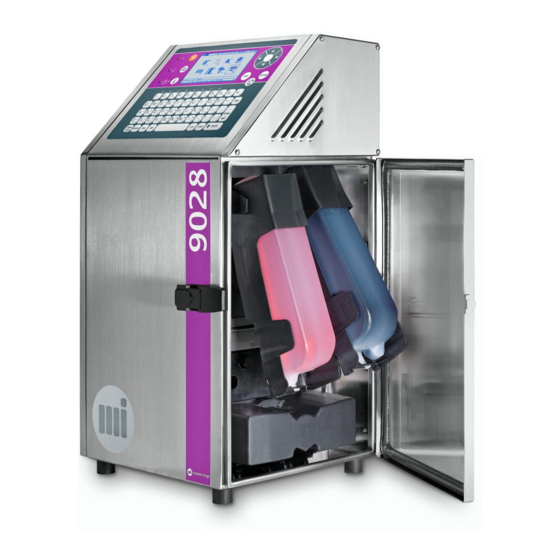
Presentation of the printer ■ Overview Housing M12 connector: tachometer (encoder) input (blue) M6’ module Ethernet port (optional) Addtitive cartridge M12 connector: RS-232 outlet Ink cartridge M12 connector: photo detector outlet (black) Operator interface Mains connector Air filter cover Umbilical 3 meters Identification label Print head Consumables access door... -
Page 12: Print Module
Presentation of the printer ■ Print module The print module comprises the umbilical and the print head. The type G, single jet head (standard characters: 2.8 pts/mm) can be used to print from 1 to 4 lines of characters depending on the fonts used. The conduit is available in a 3-meter length. - Page 13 Presentation of the printer The removable cover is opened and closed as shown in the figure below. Opening and closing the head cover Head with covers removed Head cover Protective cover Modulation assembly Umbilical Back cover Gasket Charge electrode Detection electrode Drain gutter Drain header Deflection plates...
-
Page 14: The Head Pressurization Kit (Option) And Air Filter Kit
Presentation of the printer ■ The head pressurization kit (option) and air filter kit The head pressurization kit (1) is recommended when using the printer in a dusty or humid atmosphere. The supply of dry air maintains a constant hygrometry in the head, which guarantees the proper operation of the printer and optimum print quality. -
Page 15: The Positive Air Pump Kit (Optional)
Presentation of the printer ■ The positive air pump kit (optional) The positive air pump kit performs the same function as the head pressurization kit. It is used when it is not possible to connect to a compressed air network. Positive air pump kit (reference in Spare parts catalog) A46980-AB.doc 14/176... -
Page 16: Presentation Of The Operator Interface
Presentation of the operator interface A46980-AB.doc 15/176... -
Page 17: Description Of The Interface
Presentation of the operator interface ■ Description of the interface : user : navigation : function and editing A46980-AB.doc 16/176... - Page 18 Presentation of the operator interface ■ User keys On/Off. Pressing this button allows for performing one or more test print(s). This key is for viewing the printer parameters. It can also be used for viewing and acknowledging faults or alarms signaled by the printer.
- Page 19 Presentation of the operator interface ■ Function keys Functions F1 to F8 linked to keys are only active when you are in the icons panel. Pressing these keys gives you fast access to some of the printer’s functions. For more detail, see the chapter on “Navigating in the menus”.
- Page 20 Presentation of the operator interface In Message editing, this key is for choosing the mode: □ Insertion: the cursor becomes vertical and modifications are inserted in the message without overwriting the content. e.g. TE│ST □ Overwriting: the cursor becomes horizontal and the content of the message is modified by deleting the characters pointed at by the cursor.
-
Page 21: Warning Lights
Presentation of the operator interface Pressing and holding this key when editing in lower case allows for switching to writing in upper case and back. Pressing these keys simultaneously allows for moving a page at a time towards the end of the message library list. ... -
Page 22: The Screen
Presentation of the operator interface The screen This is in the form of a 240 X 128 pixel graphic WYSIWYG screen. It is made up of various zones: ■ Main menus Functions or commands Sub-menu Ink circuit status Menu name Message heading Message number Title zone... - Page 23 Presentation of the operator interface Title zone This zone displays: □ The status of the ink circuit: ON, OFF, MAIN (maintenance), O/S (out of service) or sometimes, in some operations, the progress of sequences (e.g. n/7 for a start-up). □...
-
Page 24: Navigating In The Menus
Presentation of the operator interface ■ Navigating in the menus Using the Icons panel The panel made up of icons allows rapid access to printer some functions. It can be accessed directly when the printer is started up or by pressing the key in the main menu. - Page 25 Presentation of the operator interface ■ Description of the icons Selecting a message. This is a short-cut to the function Production/Message/Select message. Creating a new message. This is a short-cut to the function Message editing/Message/New. Modifying the message in production. Access to the parameters of the message in production.
-
Page 26: Using The Menus
Presentation of the operator interface Using the menus The main menu is the top level of the tree. It is broken down into four main menus: □ Production □ Message editing □ Printer preparation □ Symbol editing It can be accessed by pressing the key in the icons panel. -
Page 27: Navigation Help
Presentation of the operator interface Navigation help ■ Moving from the icons panel to the menu ■ Navigating in the menus To choose To exit (Icons panel) ■ Navigating in the sub-menus To choose To exit Choice of menus A46980-AB.doc 26/176... - Page 28 Presentation of the operator interface ■ Modifying a field To choose To exit Choice of sub-menus To modify Where a box has to be checked, pressing the key changes the status of the box. ■ Navigating in the functions To choose To exit A46980-AB.doc 27/176...
-
Page 29: Overview Of The Menus
Presentation of the operator interface Overview of the menus Production Printer Message Status Maint. Jet start Select message (F1) Jet maintenance (F8) Jet stop Display/init counters (F5) maintenance Manual print ElValves test General Services Fault override Message editing Message Font Variables Parameters New (F2) -
Page 30: Description Of The Main Menus
Presentation of the operator interface Description of the main menus Production: This menu contains all the functions needed for daily use and maintenance of the printer. Printer: starts or stops the printer and starts or stops the jets. It also allows for making a test print. - Page 31 Presentation of the operator interface Symbol editing: This menu contains all the functions and commands needed for creating and modifying symbols, logos and drawings. Symbol: provides access to the symbol management functions. Size: provides access to the symbols size modification function. NOTE Access to some menus can be protected with an access code.
-
Page 32: Using The Printer
Using the printer A46980-AB.doc 31/176... -
Page 33: Starting Up The Printer
Using the printer ■ Starting up the printer Daily start-up The printer is switched on when the light is lit. The ink circuit is off but all programming operations can be accessed via the menus. The icon desktop appears on the printer. -
Page 34: Star-Up After A Long Shut-Down
Using the printer ■ Automatic start-up Start-up can be performed automatically when it is switched on without pressing the key, by checking the command Printer preparation/initialization/Printer/Miscellaneous/Auto. Start Star-up after a long shut-down If the printer has been shut down for more than three weeks: Remove the front cover from the head and then the rubber... -
Page 35: Shutting Down The Printer
Using the printer ■ Shutting down the printer Daily or short shut-down (shut-down for less than 3 days) Press the key. Press the F1 : The shut-down sequence is displayed at the top left of the screen (n/4). The printer shuts off after 2 min, OFF appears at the top left of the screen. The printer is still on;... -
Page 36: Long Shut-Down
Using the printer Long shut-down ■ Shut-down lasting between 3 days and 21 days Press the key. Press the F1 : The shut-down sequence is displayed at the top left of the screen (n/4). The printer shuts off after 2 min, OFF appears at the top left of the screen. Disconnect the mains connector. - Page 37 Using the printer ■ Shut-down greater than 3 weeks. Position the head on its maintenance support. 2. Clean the printer: Production/Maint./maintenance/Clean ink circuit The cleaning procedure is described in the Chapter on “Draining/Cleaning the printer” in the Maintenance section. Press the key.
-
Page 38: Starting/Stopping The Jet(S)
Using the printer ■ Starting/Stopping the jet(s) Starting the jet(s) Production/Printer/Jet start /Jet start (Production/Maint./Jet maintenance/Jet start). Selecting this function starts the jets. During start-up the light flashes green. When the jets are ready, it is lit steadily. REMINDER When the printer starts up, the jets start up automatically. Stopping the jet(s) Production/Printer/Jet stop /Jet stop (Production/Maint./Jet maintenance/Jet stop ). -
Page 39: Initializing/Configuring The Printer
Using the printer ■ Initializing/Configuring the printer All these functions allow for initializing the printer when it is first used or changing its configuration while it is used. Choosing the dialogue language Printer preparation/Initialization/Printer/Language A dialog box allows you to choose the user language for the Operator Interface. Initializing the date and hour Printer preparation/Initialization/Printer/Date/hour This dialog box allows for setting the printer date and time. - Page 40 Using the printer ■ Using the Hijri calendar Setting the calendar parameters Printer preparation/Initialization/Message/Hijri calendar & Year Press key then enter the Hijri year. Press the key to access the parameters screen: Using the navigation arrows and the key, enter the date values for each month of the year n and n+1, then validate.
-
Page 41: Configuring The Ink Parameters
Using the printer Selecting the calendar Message editing/Parameters/Message/Hijri calendar Check this function to move to Hijri calendar mode. The dates and postdates will be displayed and prints using the Hijri calendar. Otherwise, the printer is in Julian calendar mode. Configuring the ink parameters ■... -
Page 42: Configuring The Parameters Of The Print Head
Using the printer Configuring the parameters of the print head ■ Head level Printer preparation/Initialization/Printer/Head level The dialog box allows for programming the actual head level between the head (line of the head) and the ink circuit (bottom of the console) on the production site. This value varies between –1.5 m and 2 m, in 0.5 m steps. -
Page 43: Configuring The Serial Communication Link
Using the printer Configuring the serial communication link Printer preparation/Initialization/Printer/Communication This dialog box allows for configuring the parameters of the serial communication link: □ Format: 8 w/o parity 1 stop, 8 w/o parity 2 stops or 8 even parity 1 stop. □... -
Page 44: Locking Access
Using the printer Locking access Printer preparation/Access codes This function allows for programming an access code to protect access to the menus. Press the key to enter the Access codes field. Enter a code of 1 to 3 characters, Then validate. Check the menus you wish to protect. To delete a code, enter three "spaces"... -
Page 45: Viewing The Printer Parameters
Using the printer ■ Viewing the printer parameters Several functions allow for checking the different printer parameters. Viewing the operating parameters ■ Viewing the ink circuit parameters Production/Status For fast access, press the key. On this sub-menu, you can view the status of the machine and its operating parameters in real time: □... - Page 46 Using the printer ■ Viewing the consumables level In the icon panel, the icons (ink and make-up) allow for directly viewing the level of each cartridge. In fact, each of the icons can show 6 different states depending on the cartridge status: Ink cartridge example: 100% Cartridge empty...
- Page 47 Using the printer ■ Viewing the number of prints Print preparation/Options/Totalizer This command allows for viewing a counter which shows the total number of prints made by the printer since it was first started. It increments one unit each time a message is printed, whatever set off is used. Once the final value (999999999) has been reached, it automatically returns to 0.
-
Page 48: Viewing The Programming Parameters
Using the printer Viewing the programming parameters ■ Viewing the software versions Production/Maint./General Services/Software version ■ Viewing the available algorithms Print preparation/Initialization/Algorithms This dialog box shows a list of the different algorithms available, together with their characteristics: □ No: algorithm number □... - Page 49 Using the printer ■ Viewing the machine options Print preparation/Options/Machine options This dialog box shows the printer’s hardware configuration and main software operations. NOTE The number of messages or logos indicated is the maximum value. The actual number is variable and depends on the size in bytes of the messages or logos.
-
Page 50: Exchanging Data
Using the printer ■ Exchanging data This function allows for exchanging messages and fonts between the printer and a USB key. Connecting the USB key To access the USB connector, open the door on the printer. The reader is located on the left above the cartridge-holder (1). -
Page 51: Exchanging Messages
Using the printer Exchanging messages ■ Backing up messages Printer preparation/Initialization/USB transfer/Msg Printer→USB This function makes a backup of the printer’s message library in a USB key. The messages are saved in a directory then transferred. Enter the name of the directory (maximum of 8 characters) then press enter. ATTENTION Do not disconnect the USB key during data transfer. -
Page 52: Exchanging Fonts
Using the printer Exchanging fonts ■ Loading fonts Printer preparation/Initialization/USB transfer/Font USB→Printer This command allows for selecting a *. S7S extension file from the card and loading it into the printer. It contains one or more fonts together with the associated algorithms. Loading an *. - Page 53 Using the printer A46980-AB.doc 52/176...
-
Page 54: Editing A Message
Editing a message A46980-AB.doc 53/176... -
Page 55: Selecting A Message
Editing a message ■ Selecting a message Selecting a message from the library Production/Message/Select message A dialog box shows you a list of all the messages in the printer’s memory. A message can be selected either by its number, this is the "Number-Name" mode, or by its name, this is the "Name-Number"... -
Page 56: Creating A Message
Editing a message ■ Creating a message Message Editing/Message/New Give your message a name. The name can be made up of eight alphanumeric characters. After validation, a cursor appears in the bottom left of the work zone, on the lowest line of your message. -
Page 57: Modifying A Message
Editing a message ■ Modifying a message Modifying the message in production In the icon panel, activating the icon allows for modifying the message in production. You then directly enter the menu Message editing, and the cursor appears in the message. -
Page 58: Printing A Message
Editing a message ■ Printing a message To print a message: □ the jet(s) must be ready: the light is green and lit steadily. □ the message must be in production. When these two conditions are met, a speed measurement signal from the photocell (TOP1 input) or the Tacho (Tacho input) triggers message printing. -
Page 59: Managing The Message
Editing a message ■ Managing the message Saving a message Message Editing/Message/Save Once you have finished creating a message with all its parameters and variables, it must be stored in the memory to be able to print it later if necessary; this is the role of the Save command. -
Page 60: Transferring A Message To Print
Editing a message Transferring a message to print Message Editing/Message/Load printer This command allows a message being edited to be transferred to the printer, to make a test print for example. Printing corresponds to the message editing at the time of the transfer. -
Page 61: Specifying The Print Parameters
Editing a message ■ Specifying the print parameters Specifying the parameters of a message Message editing/Parameters/Message All the data that will adapt the message to the production site appears in this dialog box. It allows for configuring the print characteristics specific to the message. Activating the icon allows for modifying the parameters of the in production message. - Page 62 Editing a message ■ Head direction The programming of this parameter depends on the installation of your printer on your production line and on the result that you want to obtain in reading. The printer offers you four configuration choices that correspond to your application. NOTE In each case, to obtain a clearly readable message, reverse the object movement direction.
- Page 63 Editing a message The process entails rotating the encoder by a number of complete revolutions (e.g. 5 complete revolutions) then measuring the distance traveled by the cable. For example, if the cable travels 1000 mm in 5 complete revolutions of the encoder, the Tacho step must theoretically be set to 40 μm.
- Page 64 Editing a message ■ Set off This function allows for choosing between the object mode, repetitive mode and multitop mode: □ Object This mode corresponds to the printing of a single message per object. Object mode options Printer preparation/Initialization/Message/miscellaneous/Top object mode Continue or Stop: If the Top object mode is Stop, printing stops when the Top information is absent (even if the message is not completely printed).
-
Page 65: Specifying The Print Resolution
Editing a message ■ Repetitive interval This parameter represents the space between two printings in Repetitive and Multitop set off. IMPORTANT - The minimum interval value is 9 mm. - The maximum interval value is 1400 mm. ■ Algorithm number This function is used for selecting an algorithm number. -
Page 66: Specifying The Characteristics Of The Characters
Editing a message ■ Specifying the characteristics of the characters These functions will allow you to choose the type, style and size of your characters or your symbols. Selecting a font Message editing/Font/select Font After validating a font, the cursor takes the height of the font selected. The fonts correspond to the keyboard characters for Cyrillic, Arabic, Hebrew and the languages that use the Latin alphabet. -
Page 67: Using Tabulation
Editing a message Using tabulation Message editing/Font/Tabulation This function allows for specifying a new blank area between two characters or symbols different from the standard space of the font used. In general, the space has the same width as a normal character, with this command you can determine its width (1 to 255 points). - Page 68 Editing a message ■ Bit mode Pressing the key (space) inserts tabulations. These tabulations are made up of a number of bits programmed in this function. By placing the cursor in front of a tabulation, the help area shows you "tabulation x" with x representing the number of bits in this tabulation.
-
Page 69: Bolderizing A Character
Editing a message Bolderizing a character Message editing/Font/Bolderization This function allows for the printing in bold the characters that you want to stand out in the message, without changing their height. You are offered a dialog box in which you program the bolderization coefficient needed between 1 and 9, 9 being the thickest print (by default this coefficient is on 1). -
Page 70: Using The Date And Hour
Editing a message ■ Using the date and hour To print the date and hour in a message, there are parameters that must first be set, then they must be composed and lastly, inserted in a message. Setting the date and hour parameters ■... -
Page 71: Composing And Inserting The Date
Editing a message Composing and inserting the date Message editing/Variables/Date This menu allows you to insert the calendar items in your message. A dialog box offers to compose your "Date" variable using the following items: The Entry line displays the date items as they are programmed. Once the date is composed, pressing the key inserts it in the message where the cursor is positioned. -
Page 72: Composing And Inserting The Hour
Editing a message Composing and inserting the hour Message editing/Variables/Hour This menu allows you to insert the hour items in your message. A dialog box offers to compose your "autodating" variable using the Hours, Minutes, Seconds and Separators (:/. ) fields, in any order you wish. The Mode field displays AM, PM or a blank in 24 mode. -
Page 73: Using A Counter
Editing a message ■ Using a counter To print a counter, the parameters must be set then inserted in the message. It can also be viewed then reset to its starting value. You can insert up to 2 different counters per message. Setting the parameters of a counter Message editing/Parameters/Counter The dialog box allows you to select a counter. - Page 74 Editing a message ■ Base For selecting the counter’s numbering base. Once the base is specified, the counter’s Starting value and Final value are replaced in the values allowed by the base. □ 10 (0-9): standard digital. Goes from 0 to 9. □...
-
Page 75: Inserting A Counter
Editing a message ■ Batch counter 0000 to 9999 – This is the object number in the batch. The counter increments when this value is reached. ■ Progression mode Inactive Fixed counter the counter is incremented according to the information from the Top Object object input Message... -
Page 76: Viewing And Initializing Counters
Editing a message Viewing and initializing counters Production/Message/Display/init counters This command allows you to view the value of the counters and reset them to their starting values as needed. Select the counter number from the groups offered, then validate. When the counter value is displayed, you can insert its starting value by checking the corresponding box using the key, then validate. -
Page 77: Using A Postdate
Editing a message ■ Using a postdate A postdate is a date deferred in relation to the current date. To print a postdate, its parameters must first be set, then it is composed and lastly it is inserted in the message. You can insert up to 6 different postdates per message. -
Page 78: Default Parameters
Editing a message ■ Modulo This parameter allows for coding the postdate: Postdate = Date + R with R = Postdate period (in days) – (n x Modulo) Example: 01 January 2014, an operator enters a postdate period of 1000 days, the postdate value will vary according to the modulo chosen: Modulo Postdate... -
Page 79: Composing And Inserting A Postdate
Editing a message Composing and inserting a postdate Message editing/Variables/Postdate This menu allows you to insert the postdate items in your message. A dialog box allows you to compose your "Postdate" variable using the following items: ■ Postdate 1 The figure indicates the postdate number. Example: D1 signifies PostDay month of Postdate 1. -
Page 80: Using A Shift Code
Editing a message ■ Using a shift code A shift code allows for printing a set of values contained in a circular list according to a period for changing at a given value. The code is specified using a given time and day and it is common to all messages. - Page 81 Editing a message ■ Shift code 2 This allows for printing information on cycled times over a period greater than one day. ■ Shift code 3 This allows for programming the starting time (in AM, PM or 24 mode) and the interval for each day of the week.
-
Page 82: Inserting A Shift Code
Editing a message Inserting a shift code Message editing/Variable/shift code Select a shift code from the 3 offered, then validate. ■ Shift code 1 A dialog box allows you to choose from three possible shift code displays: Letter (-I-O): The letters I and O will not be used for composing the shift code. Once your choice is validated, a character (alphabetic or numerical) appears in your message at the point your cursor is positioned. -
Page 83: Using The Autodating Table
Editing a message ■ Using the autodating table This function allows for inserting all the time and date variables coded using the autodating table. To print an autodating item, its parameters must first be set and then it is inserted in the message. - Page 84 Editing a message Example: Encoding the time □ Field: 1/24 informs you that you are entering the code corresponding to the first hour. Coding 24 fields corresponds to the 24 hours in a day. □ Value: this is the field that you actually enter. In this case, it is the first (default value 000).
-
Page 85: Composing And Inserting An Autodating Item
Editing a message Composing and inserting an autodating item Message editing/Variables/Autodating table This menu allows you to insert the coded autodating items in your message. A dialog box allows you to compose your "Autodating table" variable using the following items: Pressing the key allows for inserting it in the message at the point the cursor is positioned. -
Page 86: Using External Variables
Editing a message ■ Using external variables Message editing/Variables/External This function allows for reserving locations for variables information to be sent by RS232/V24 external link inside a message (example: weight from scales or information from a computer, from a bar code reader). If no information is sent, these reserved locations will be represented in print by a symbol chosen which is visible on the screen. -
Page 87: Using A Barcode (Option)
Editing a message ■ Using a barcode (option) To edit a barcode its parameters must first be set, then it is set and lastly inserted in the message. You can insert up to 3 different barcodes per message. Setting the barcode parameters Message editing/Parameters/barcodes A dialog box offers you a choice of a maximum of 3 codes (barcode or Datamatrix code). - Page 88 Editing a message ■ Plain text Only for distribution codes – allows for choosing whether or not the code is printed as human readable text, as well as the position of this text: None Upper Lower 1114444ùùù444444111 44kkkkkkkkkkkk444 ■ Height Barcode Between 5 and 28 points - limited by the height of the fonts present.
- Page 89 Editing a message ■ Narrow bar From 1 to 4 (bit) - default value 1 for distribution codes. ■ Narrow space From 1 to 4 (bit) - default value 1 for distribution codes. ■ Wide bar From 2 to 9 (bit) - default value 2 for distribution codes. ■...
-
Page 90: Composing And Inserting The Barcode
Editing a message Composing and inserting the barcode Message editing/Font/Barcode You can insert up to 3 codes (barcodes or Datamatrix code) of different types in your message using this command. A dialog box offers you a choice of 3 codes identified by their type. Select the desired barcode then validate. -
Page 91: Barcode Characteristics
Editing a message Barcode Characteristics ■ Industrial codes 2/5 interleaved □ Allows for transcribing digital characters in barcode only. □ These characters may be variable (counter, date, etc.). □ 32 characters maximum. The dialog box is as follows: If check digit □... - Page 92 Editing a message ■ Distribution codes 42222222222 cursor signals the bottom of the barcode assembly (bars + human readable text) whatever the position of the human readable text. You can print the bars and the cleartext on a single jet. Pay attention to the height of the bars and the cleartext.
- Page 93 Editing a message EAN 128 and code 128 The dialog box is as follows: □ 47 characters maximum. □ The set of characters is divided into 4 menus that can be found in Mode 128 (Code A, Code B, Code C) and Characters to: Code A: comprises all the standard upper case alphanumeric characters, the command characters and the special characters.
- Page 94 Editing a message HIBC This code has the same characteristics as code 128 Mode C. □ The Optimization parameter is not valid. □ There is no Default mode. □ The first two characters are between parentheses. The dialog box is the same as that of EAN 128/code 128. HIBC LIC The basic data must be symbolized either in Code 128 or Code 39.
- Page 95 Editing a message ■ Datamatrix Code □ The code used is ECC200 type with automatic format calculation (square or rectangle). □ The height of the code can vary between 8 and 24 points. □ The size of the cells (bolderization) is programmable: 1 or 2 drops. □...
-
Page 96: Using Symbols
Editing a message ■ Using symbols A symbol can be an alphabetic character, a number, a special symbol or a special shape (logo). A set of symbols of the same size constitutes a font. You can create maximum of 10 fonts. Chinese symbols are edited using a Pin Yin editor. -
Page 97: Creating A Symbol
Editing a message Creating a symbol ■ General rule Create the font: □ Give the font a name (8 characters). □ Give the font a number (201 to 255). □ Give the symbol in the font a number (001 to 224). Specify the size of the symbols: □... - Page 98 Editing a message ■ Creating a font and specifying the size of the symbols Symbol editing/Symbol/New This command allows you to create a new symbol that will be filed in a font. The dialog box asks you to provide: □ a title for the font (8 characters max), □...
- Page 99 Editing a message ■ Creating the symbol Screen After specifying the font’s name, number, symbol number and size, the printer offers you the following screen. Number of existing symbols in the font Symbol number Font number Font name Coordinates of the cursor in the grid Draw mode >>...
- Page 100 Editing a message Using the keys In mode: Point by point >> Allows for moving the cursor in the drawing grid, in the direction of the arrows.
- Page 101 Editing a message In mode: zone Allows for choosing the color of the zone (white or black). Successively pressing 2 keys allows for specifying a zone. ...
-
Page 102: Saving A Symbol
Editing a message Zoom This function is valid when the cursor is at the bottom left of the screen (coordinates 001 x 001). Use the keys to enlarge or reduce the grid. Delete symbol key with confirmation requested. Saving a symbol Symbol editing /Symbol/Save This command allows you to save the symbol you have just created or modified. -
Page 103: Modifying A Symbol
Editing a message Modifying a symbol ■ Modifying a symbol Symbol editing /Symbol/Open This command allows for modifying an existing symbol after it is selected. Once you choose Open, a dialog box offers you a list of existing symbol fonts. You can then scroll down the titles and choose the one that interests you or display a cursor using key and enter the title of the font you are looking for, then validate. -
Page 104: Editing Chinese Symbols
Editing a message ■ Modifying the size of a symbol Symbol editing /Size/Symbol size This function allows for modifying the height and width of the symbols specified in a font. ATTENTION - If you reduce the size, the symbols already drawn will be truncated. - Page 105 Editing a message keys are for moving in the list offered. Pressing keys allows for selecting the ideogram concerned. It then appears in the composition zone: Pressing the keys deletes the last ideogram, combining deletes the whole zone. Once the composition is completed, pressing the key allows for inserting the ideograms into the message at the location of the cursor: A46980-AB.doc...
-
Page 106: Example Of Programming Messages
Editing a message ■ Example of programming messages ■ Creating a message Font 7 pts 12:01:14 PARIS: 0 4 2 Font 7 pts Font 16 pts Bolderization 2 Postdate DIRECTIONS FOR PROCESSING WHAT YOU NEED THE ABOVE EXAMPLE TO USE All the functions needed for creating a message are in the Message editing menu. - Page 107 Editing a message New is used to create a new message. key to validate the New stage. Identify the message by giving it a title made up of a maximum of 8 upper case alphanumeric characters. Direct access from the icon panel allows access to this screen.
- Page 108 Editing a message Bolderize to make the "042" characters appear thicker. keys then keys. The Bolderization function is in the sub- menu Font. Any character or symbol in any font can be bolderized. Select Bolderization with (X 2) then press the key.
- Page 109 Editing a message Before inserting the postdate in the message, enter the postdate’s value. key (X 2) then key. For all variables, it is preferable to enter their parameters first, before inserting them in the message. Press key (X 2) to select the Postdate line, then press the key.
- Page 110 Editing a message Choose a 16 point font and a bolderization of 1 to write the postdate in large characters in relation to the rest of the message. key then key (X 2) then press the key. press the .key The different fonts available in the machine appear in a dialog box.
- Page 111 Editing a message Inserting the postdate key then key, then key then key (X4). Press the key Select postdate 1 then For all the dialog boxes, the pre-selections are made with the navigation arrows then the choice is made with the key.
- Page 112 Editing a message The message is created. What you see on the screen is what is printed (WYSIWYG). To print it, the print parameters must correspond to the printer installation in the production site. keys then press the key. Press the The default values of these parameters are the values inserted in the Printer preparation menu when the printer was installed.
- Page 113 Editing a message Saving the message key then key then key. In this sub-menu you can carry out a Load printer for the message on the screen to carry out a test print (using the key on the operator interface, for example). This function is used when adjusting the message parameters and the form of the message.
-
Page 114: Servicing
Servicing A46980-AB.doc 113/176... -
Page 115: Cleaning The Head
Servicing ■ Cleaning the head Special tools □ Drainage tray □ Cleaning flask, blower (or drying kit) Stop the jet(s) by pressing the F8 key then selecting and validating the Jet stop function. Position the head on its maintenance support. Open the head cover. - Page 116 Servicing Clean the electrode and the cannon with the cleaning solution. In the event that certain inks are used (refer to the safety data sheet for your ink), or if the printer is used in a harsh environment (high temperature, dusty surroundings), operations 5, 6 and 7 are to be carried out.
- Page 117 Servicing Dry carefully. Using the blower or drying kit if this is specified on the ink technical sheet. Restart the jet by selecting and validating Jet start. Close the head cover and acknowledge the cover fault by pressing key or Replace the head on its operating support.
-
Page 118: Protect The Head
Servicing ■ Protect the head A46980-AB.doc 117/176... -
Page 119: Correctly Starting The Jets
Servicing ■ Correctly starting the jets If the jet does not start up correctly (no jet or jet deflected), there are several functions for completely resetting the jet. Production/Maint./Jet Maintenance Use the screen instructions to guide you for the three functions. The head is on its maintenance support and the cover has been removed. - Page 120 Servicing Validate the function: Check jet stability Once the jet is stable, shut down the stability control. Clean the head. Once this phase has been completed, restart the jet by validating the function: Jet start Visually check the presence of the jet in the gutter. Close the head cover and press key to acknowledge the faults.
- Page 121 Servicing A46980-AB.doc 120/176...
-
Page 122: Maintenance
Maintenance A46980-AB.doc 121/176... -
Page 123: Maintenance Menus
Maintenance ■ Maintenance menus Using the desktop icons The desktop consisting of icons gives rapid access to certain printer functions. It can be accessed from the main desktop (see page 23) and then pressing Description of icons View the printer information (serial No., messages in library, operating hours and number of printouts) (see page 125). -
Page 124: Description Of The Maintenance Icons
Maintenance Description of the maintenance icons Access the maintenance operation records. This is a short cut to the function Production/Maint/ General Services/record an Operation (see page 127). Access the printer draining and flushing functions (see page 133). Access the ink circuit test mode. Fault monitoring override. -
Page 125: Maintenance Management
Maintenance ■ Maintenance management Production/Maint./ General Services Maintenance management is carried out by various functions in this menu. It forms a maintenance log that can be viewed or added to during maintenance operations (e.g. part replacement). Viewing the maintenance data ■... - Page 126 Maintenance ■ Viewing the maintenance parameters Production/Maint./General Services/Printer information This function allows for viewing 2 types of information: The printer configuration: □ Type: indicates the printer configuration name: □ SN: indicates the serial number. □ Mes in lib: the maximum number of messages in the library. The actual number is variable and depends on the size in bytes of the messages.
-
Page 127: View The Information On Module M6
Maintenance View the information on module M6’ This function allows 3 types of information to be viewed: - the serial number of the module M6’, - the date of installation of the module M6’, - the number of hours for which the module has been in operation and its maximum operating time. -
Page 128: Recording A Maintenance Operation
Maintenance Recording a maintenance operation Production/Maint./General Services/record an Operation This menu allows for recording and acknowledging maintenance operations. Press the key to open the Operation field: Select the field for the operation and confirm. Then enter the part’s article code in the Code field and any comments in the Comments field. -
Page 129: Exporting The Log File
Maintenance ■ Preventive maintenance Fields Air filter change, Press. filter change, IC change are the three preventive maintenance groups: □ Air filter change: change the air inlet and air outlet filters. □ Press. filter change: change the pressurization filter on the head pressurization kit. □... - Page 130 Maintenance Fault and alarm history / □ printer status history □ information on the module M6’: - serial number - date of first use of the module M6’ (date of installation) - operating time The log file thus indicates the file containing these records. This file is in *.HST format The file name format is "Lcountry code serial number.HST"...
-
Page 131: Overriding Cover And Drain Faults
Maintenance ■ Overriding cover and drain faults Production/Maint./Fault override When carrying out servicing or maintenance operations, it may be desirable to turn off the open cover fault and drain fault control. This function overrides these faults, i.e. they are no longer managed. Each time the printer is shut down, this function returns to its initial value. -
Page 132: Adjusting The Break Off Point Setting
Maintenance Adjusting the break off point setting Special tools: □ Magnifying glass (shaded eyepiece) □ 2.5 mm hexagonal key or Flat-headed screwdriver ■ Prior operations Place the head on the maintenance support. Turn on the jet and let it run for at least 1/2 an hour. Remove the head cover. - Page 133 Maintenance □ Correct adjustment is set only by the shape of the drops immediately under the break off point setting: Avoid Good Figure 2 NOTE When making the adjustment, handle the adjustment screw with care to avoid damaging it. ■ Final operations Close the head cover.
-
Page 134: Draining/Cleaning The Printer
Maintenance ■ Draining/Cleaning the printer Draining the printer Production/Maint/Maintenance/Drain If you select this function, you will completely empty the ink from printer. This drainage is connected with some particular maintenance operations. Follow the instructions on the screen. A46980-AB.doc 133/176... -
Page 135: Cleaning The Printer
Maintenance Cleaning the printer Production/Maint/maintenance/Clean ink circuit By validating this function, the printer will carry out a complete drain, then automatically clean the ink circuit with make-up. This function also flushes all the umbilical and head parts. 2-3 depressurized empty cartridges are needed. After flushing, a machine can be put into storage for several months. -
Page 136: Replacing Filters
Maintenance ■ Replacing filters In order to establish a maintenance log, these operations must be saved in the General services function. For more details, consult the chapter on “Managing maintenance”. The air inlet and outlet filters must be changed annually if the printer is in daily use. Replacing the air inlet filter ■... - Page 137 Maintenance Remove the used foam. Insert the new foam, ensuring that it is correctly positioned. Refit the plastic cover. Connect the printer to the mains supply and restart it. A46980-AB.doc 136/176...
-
Page 138: Replacing The Air Outlet Filter
Maintenance Replacing the air outlet filter ■ Procedure A46980-AB.doc 137/176... - Page 139 Maintenance Insert the new foam, ensuring that it is correctly positioned in its seating. Reassemble in the inverse order of disassembly. A46980-AB.doc 138/176...
-
Page 140: Replacing The Pressurization Air Filter
Maintenance Replacing the pressurization air filter Stop the printer and unplug the power cable from the main supply.. Disconnect the air inlet or close the valve. Unscrew the air filter tank from the air treatment unit and pull it downwards. Unscrew the filter. -
Page 141: Replacement Of The Module M6
Maintenance Replacement of the module M6’ The module M6’ must be replaced every 6000 hours. ■ Procedure Follow the instructions on M6' replacement the screen. Remove the additive cartridge and confirm. After about 45 s, the display will indicate "Over". A46980-AB.doc 140/176... - Page 142 Maintenance Remove the ink cartridge: A46980-AB.doc 141/176...
- Page 143 Maintenance Put the used module M6’ in its original box with the protective foam wedges. As waste, the module M6’ must be dealt with in accordance with the local regulations regarding waste management and the transport of dangerous goods A46980-AB.doc 142/176...
-
Page 144: Inserting The New Module M6
Maintenance Inserting the new module M6’ A46980-AB.doc 143/176... - Page 145 Maintenance A46980-AB.doc 144/176...
-
Page 146: Testing The Electrovalves
Maintenance ■ Testing the electrovalves Production/Maint/elValves test This test allows for manually operating the 4 electrovalves in the ink circuit and the 4 electrovalves in the head (A to D). The ink circuit is in stand by mode. When this screen is displayed, all the electrovalves are closed. They can be operated individually in open ( or closed ( status by pressing the... - Page 147 Maintenance A46980-AB.doc 146/176...
-
Page 148: Alarms And Faults
Alarms and faults A46980-AB.doc 147/176... -
Page 149: Viewing A Fault Or An Alarm
Alarms and faults ■ Viewing a fault or an alarm If one or more faults/alarms appear, the warning light : □ flashes to signal an alarm (not blocking print), □ is lit steadily to signal a fault (blocking print). For an ink or make-up fault/alarm, the corresponding icon (F6 or F7) also flashes. -
Page 150: Viewing The List Of Faults
Alarms and faults Viewing the list of faults Production/Maint./General Services /List of faults When validating this function, a list of the last thirty printer faults and alarms appears in a dialogue box, in the order they occurred. If the information is spread over several pages, use the keys to reach the other pages. -
Page 151: Table Of Faults And Alarms
Alarms and faults Table of faults and alarms A: Alarm F: Fault N° Recommendation Message displayed Supply valves IC Call Markem-Imaje service** Change M6' Replace M6’ Recuperation sensor out of service Call Markem-Imaje service** HV supply overload Check cleanliness head Piezo supply overload Check cleanliness head External communication timeout... - Page 152 Alarms and faults N° Message displayed Recommendation Ambient pressure measurement failed Call Markem-Imaje service** Ink transfer timeout Call Markem-Imaje service** Printer empty. No more ink available Place a full ink cartridge Full tank Drain printer Ink cartridge unknow Change the ink cartridge Drop detection Clean and dry carefully head + cover Ink concentration out of range...
-
Page 153: Preliminary Checks
Alarms and faults ■ Preliminary checks Any search for faulty components should always start with preliminary checks. Carrying out these checks allows for checking for problems such as dirt on the components, ink leaks or electrical connections with the naked eye. External appearance Sub-assemblies to check Type of malfunction looked for... -
Page 154: Trouble-Shooting
Alarms and faults ■ Trouble-Shooting Introduction The tables in this chapter show the following 2 columns: □ Malfunction. □ Remedies. Each malfunction is marked in the table with a number in bold. Each of the malfunctions can be resolved using several "Remedies". Example of a diagnostic Malfunction Actions and remedies... -
Page 155: When Using The Printer
Alarms and faults When using the printer Malfunction Actions and remedies 1- Blank screen. 1a- Check the power supply. 1b- Check the power cord and its connection. 2- Red alarm indicator/fault lit/flashes. 2a- Perform a self-diagnosis by pressing the ke y on the Operator Interface. -
Page 156: While The Printer Is Operating
Alarms and faults While the printer is operating Malfunction Actions and remedies 1- Low ink level. Prep. cartridge: 1a- Prepare a new ink cartridge. 2- Low make-up level. Prep. 2a- Prepare a new make-up cartridge. cartridge: 51 3- Empty ink level: 52 3a- Replace the ink cartridge. - Page 157 Alarms and faults Malfunction Actions and remedies 9- Defective EHV power supply: 9a- Carefully clean and dry the head and cover electrodes. Defective EHV insulation: 87 9b- Ensure that the environmental conditions (humidity, temperature) conform to the specifications given in the ink technical file. If this is not the case, contact Markem-Imaje Technical Assistance to adapt the head pressurization accessories to dry air.
- Page 158 Alarms and faults Malfunction Actions and remedies 12- Print speed off specif.: 40 12a- Re-enter the "Tacho Division" setting on the printer, in the Message Parameters Menu. 12b- Choose another algorithm. 12c- Contact Markem-Imaje Technical Assistance. 13- Algo not available: 48 13a- The programmed printing speed is too high according to the message content.
- Page 159 Alarms and faults Malfunction Actions and remedies 17- Poor print quality 17a- Clean the print head (including cover) and check Example 1: there is no obstacle along the jet’s trajectory. 17b- Check the stability of the head support (no vibrations). 17c- Check the head/object distance (examples 1 and 2).
-
Page 160: Technical Specifications
Technical Specifications A46980-AB.doc 159/176... -
Page 161: Physical Description
Technical Specifications Physical description Dimensions (mm) □ Printer cabinet......400 x 355 x 215 □ Print head (right) ....... 182 x 36 x 43 □ Consumables cartridge ..... 250 x 55 x 55 Weight (kg) □ Whole machine ......18.5 kg □... -
Page 162: Limits Of Use
Technical Specifications Limits of use Operating temperature □ + 5°C to + 40°C. (The use of some inks may limit the temperature range, see inks technical sheets). Humidity □ 0 to 90 % without condensation. Altitude □ 2000 m maximum. Installation conditions Printer operating position □... -
Page 163: Characteristics
Technical Specifications Characteristics Fonts □ Industrial Latin. □ Languages edited by the printer. □ Chimney, etc. For more detail, see following pages. Autodating □ Hour, minute, second. □ Day, month, year, Julian day, day of the week, last figure of the year, up to 3 shift codes, up to 6 postdates, autodating table. -
Page 164: List Of Fonts
Technical Specifications List of fonts Description Format Number of Number COMMENTS (16 chars.) (H*L) characters Latin Ind. 7 07 * 06 Latin Ind. 16 16 * 12 Latin Ind. 24 24 * 21 Chimney 5 Ext 05 * 06 Chimney 7 Ext 07 * 08 Cyrillic 7 Ext 07 * 07... - Page 165 Technical Specifications Description Format Number of Number COMMENTS (16 chars.) (H*L) characters py00 PINYIN12 12 * 12 PINYN 12 Entetete py01 PINYIN 16 16 * 15 PINYIN py02 PINYIN 16 16 * 15 PINYIN py03 PINYIN 16 16 * 15 PINYIN py04 PINYIN 16 16 * 15...
- Page 166 Technical Specifications Description Format Number of Number COMMENTS (16 chars.) (H*L) characters Hebrew 16 16 * 12 Hebrew alphabet Hebrew 16 16 * 12 Latin alphabet Hebrew 7 07 * 06 Hebrew alphabet Hebrew 7 07 * 06 Latin alphabet Arabic 24 Ext 24 * 20 Japanese 24 Ext...
-
Page 167: List Of Algorithms
Technical Specifications List of algorithms Number of droplets Total number of Maximum Type of Vertical Head-target Description (dots) of full grid droplets (dots) velocity in head resolution distance printed in full grid G10_28_1x05_LP_005_0001 10 mm 4,464 G10_28_1x07_LP_007_0002 10 mm 3,189 G10_28_1x16_NF_017_0003 10 mm 1,313... -
Page 168: Overall Dimensions
Technical Specifications Overall dimensions ■ Console A46980-AB.doc 167/176... - Page 169 Technical Specifications ■ Head A46980-AB.doc 168/176...
-
Page 170: External Connections
External connections A46980-AB.doc 169/176... -
Page 171: Location Of Sockets And External Accessory Connections
External connections ■ Location of sockets and external accessory connections Photocell connector The detector is connected to this connector. (black) When the detector is activated by a passing object, it sends a signal to the printer which triggers printing. Tachometer (encoder) When the conveyor speed is variable, the connector (blue) tachometer input can be used to connect a... -
Page 172: Connection Of Optional Accessories
External connections ■ Connection of optional accessories For more information on these operations, contact the Markem-Imaje technical assistance or your distributor. Procedure Connect the specific connection kit for the accessory to the CPU board (see diagram on following page). A46980-AB.doc 171/176... - Page 173 External connections Alarm warning light RS232 link Tachometer (encoder) A46980-AB.doc 172/176...
-
Page 174: Alarm And Fault Outputs For The Alarm Warning Light
External connections Alarm and fault outputs for the alarm warning light Configuring the alarm and fault outputs Printer preparation/Initialization/Printer/Miscellaneous/Alarm relay/Fault With these functions, the alarm and fault outputs can be configured. Mode Standb Start-up Machine ready Alarm Empty Shut-down Color when phase to print... - Page 175 External connections A46980-AB.doc 174/176...
-
Page 176: User Manual
05/ 2005 Revision 11/ 2006 03/ 2007 05/ 2008 ■ 9028 User Manual Instructions update . The revision A index corresponds to the first edition of this manual. . The revision index changes with each update. Date published Revision index documentation... - Page 177 A46980-AB.doc 176/176...
Need help?
Do you have a question about the 9028 and is the answer not in the manual?
Questions and answers